Table Of Contents
Managing Ethernet Virtual Circuit (EVC) Services
Getting Started
Overview
Prepopulating a Service by Selecting Endpoints in Prime Network
Installing Prime Provisioning and Configuring the Network
Configuring the Network to Support Layer 2 Services
Setting Up Basic Prime Provisioning Services
Setting Up Providers, Customers, and Devices
Setting Up the N-PE Loopback Address
Setting Up Prime Provisioning Resources for EVC Services
Setting Up NPCs
Setting Up VPNs
Working with EVC Policies and Service Requests
A Note on Terminology Conventions
Setting Up the Prime Provisioning Services
Creating Target Devices and Assigning Roles (N-PE or U-PE)
Configuring Device Settings to Support Prime Provisioning
Configuring Switches in VTP Transparent Mode
Setting the Loopback Addresses on N-PE Devices
Setting Up Devices for IOS XR Support
Defining a Service Provider and Its Regions
Defining Customers and Their Sites
Defining VPNs
Creating Access Domains
Creating VLAN Pools
Creating Outer VLAN Pools
Creating a VC ID Pool
Creating Named Physical Circuits
Creating NPCs Through the NPC GUI Editor
Creating a Ring-Only NPC
Terminating an Access Ring on Two N-PEs
Creating NPC Links Through the Autodiscovery Process
Creating and Modifying Pseudowire Classes
Creating a Pseudowire Class
Modifying a Pseudowire Class
Deleting a Pseudowire Class
Configuring the Transport Mode When Pseudowire Classes are Not Supported
Defining L2VPN Group Names for IOS XR Devices
Creating an EVC Ethernet Policy
Overview
Defining the EVC Ethernet Policy
Managing an EVC Ethernet Service Request
Overview
Creating an EVC Service Request
Setting up Links to the N-PE
Using Templates and Data Files with an EVC Ethernet Service Request
Saving the EVC Ethernet Service Request
Modifying the EVC Ethernet Service Request
Deploying the EVC Ethernet Service Request
Creating an EVC ATM-Ethernet Interworking Policy
Overview
Defining the EVC ATM-Ethernet Interworking Policy
Customizing EVC and MPLS Policies
Managing an EVC ATM-Ethernet Interworking Service Request
Overview
Creating an EVC ATM-Ethernet Interworking Service Request
Setting up Links to the N-PE
Using Templates and Data Files with an EVC ATM-Interworking Service Request
Saving the EVC ATM-Interworking Service Request
Modifying the EVC ATM-Interworking Service Request
Deploying the EVC ATM-Ethernet Service Request
Defining Frame Relay Policies
Defining ATM Policies
Managing a VPLS Service Request
Overview
Creating a VPLS Service Request
Creating a VPLS Service Request with a CE
Creating a VPLS Service Request without a CE
Using Templates and Data Files with a VPLS Service Request
Saving the VPLS Service Request
Modifying the VPLS Service Request
Deploying, Monitoring, and Auditing Service Requests
Pre-Deployment Changes
Provisioning VPLS Autodiscovery on Devices using EVC Service Requests
Overview
Limitations and Restrictions for VPLS Autodiscovery
Preconfiguring PE Devices to Support VPLS Autodiscovery
Enabling VPLS Autodiscovery in the EVC Workflow
Sample Configlets
Policy and Service Request Attributes Reference Tables
EVC Ethernet Service Attributes
EVC Ethernet Policy Attributes
EVC Ethernet Service Request Attributes
EVC ATM-Ethernet Interworking Service Attributes
EVC ATM-Ethernet Interworking Policy Attributes
EVC ATM-Ethernet Interworking Service Request Attributes
Sample Configlets
Overview
ERS (EVPL) (Point-to-Point)
ERS (EVPL) (Point-to-Point, UNI Port Security)
ERS (EVPL) (1:1 VLAN Translation)
ERS (EVPL) (2:1 VLAN Translation)
ERS (Pseudowire Class, E-Line, L2VPN Group Name, IOS XR Device)
ERS (EVPL) (NBI Enhancements for L2VPN, IOS Device)
ERS (EVPL) and EWS (EPL) (Local Connect on E-Line)
ERS (EVPL), EWS (EPL), ATM, or Frame Relay (Additional Template Variables for L2VPN, IOS and IOS XR Device)
EWS (EPL) (Point-to-Point)
EWS (EPL) (Point-to-Point, UNI Port Security, BPDU Tunneling)
EWS (EPL) (Hybrid)
EWS (EPL) (Pseudowire Class, E-Line, L2VPN Group Name, IOS XR Device)
EWS (EPL) (NBI Enhancements for L2VPN, IOS Device)
ATM over MPLS (VC Mode)
ATM over MPLS (VP Mode)
ATM (Port Mode, Pseudowire Class, E-Line, L2VPN Group Name, IOS XR Device)
Frame Relay over MPLS
Frame Relay (DLCI Mode)
VPLS (Multipoint, ERMS/EVP-LAN)
VPLS (Multipoint, EMS/EP-LAN), BPDU Tunneling)
EVC (Pseudowire Core Connectivity, UNI Port Security)
EVC (Pseudowire Core Connectivity, UNI, without Port Security, with Bridge Domain)
EVC (Pseudowire Core Connectivity, UNI, and Pseudowire Tunneling)
EVC (VPLS Core Connectivity, UNI Port Security)
EVC (VPLS Core Connectivity, no UNI Port Security)
EVC (Local Connect Core Connectivity, UNI Port Security)
EVC (Local Connect Core Connectivity, UNI, no Port Security, Bridge Domain)
EVC (Pseudowire Core Connectivity, Bridge Domain, Pseudowire on SVI)
EVC (Pseudowire Core Connectivity, no Bridge Domain, no Pseudowire on SVI)
EVC (AutoPick Service Instance Name)
EVC (No AutoPick Service Instance Name, No Service Instance Name)
EVC (Pseudowire Core Connectivity, User-Provided Service Instance Name)
EVC (Pseudowire Core Connectivity, Pseudowire Redundancy, "A" - "Z")
EVC (Pseudowire Core Connectivity, Pseudowire Redundancy, "A", "Z", and "Z '")
EVC (Pseudowire Core Connectivity, Pseudowire Redundancy, "A", "Z", and "Z '", where "Z" = "Z '")
EVC (Pseudowire Core Connectivity, Service Instance Syntax on L2 Access Nodes)
EVC (Pseudowire Core Connectivity, Mixture of Switchport and Service Instance Syntax on L2 Access Nodes, Push Outer Enabled)
EVC (Pseudowire Core Connectivity, Service Instance Syntax on L2 Access Nodes, Push Both Enabled)
EVC (Pseudowire Core Connectivity, Static Pseudowire, IOS Device)
EVC (Pseudowire Core Connectivity, Static Pseudowire, IOS Device, Pseudowire Redundancy)
EVC (Pseudowire Core Connectivity, Static Pseudowire, IOS Device, Bridge Domain Disabled)
EVC (Pseudowire Core Connectivity, Pseudowire Service with BVI)
EVC (Pseudowire Core Connectivity, Static Pseudowire, OAM Class Set in DCPL Property)
EVC (Local Core Connectivity, User-Provided Service Instance Name)
EVC (VPLS Core Connectivity, User-Provided Service Instance Name)
EVC (ATM-Ethernet Interworking, Pseudowire Core Connectivity, Point-to-Point Circuit)
EVC (ATM-Ethernet Interworking, Pseudowire Core Connectivity, Multipoint Circuit)
EVC (ATM-Ethernet Interworking, Local Core Connectivity, Point-to-Point Circuit)
EVC (ATM-Ethernet Interworking, Local Core Connectivity, Multipoint Circuit)
EVC (ATM-Ethernet Interworking, Local Core Connectivity, Point-to-Point Circuit)
EVC (ATM-Ethernet Interworking, Pseudowire Core Connectivity, End-to-End Circuit)
EVC (ATM-Ethernet Interworking, Pseudowire Core Connectivity, Multipoint Circuit)
EVC (ATM-Ethernet Interworking, Local Core Connectivity, Point-to-Point Circuit)
EVC (ATM-Ethernet Interworking, Pseudowire Core Connectivity, End-to-End Circuit, with Bridge Domain)
EVC (ATM-Ethernet Interworking, Pseudowire Core Connectivity, End-to-End Circuit, no Bridge Domain)
Managing Ethernet Virtual Circuit (EVC) Services
This chapter describes how to use Prime Provisioning policies and service requests to manage various Ethernet Virtual Circuit services. It contains the following sections:
•
Setting Up the Prime Provisioning Services
•
Creating an EVC Ethernet Policy
•
Managing an EVC Ethernet Service Request
•
Creating an EVC ATM-Ethernet Interworking Policy
•
Customizing EVC and MPLS Policies
•
Managing an EVC ATM-Ethernet Interworking Service Request
•
Deploying, Monitoring, and Auditing Service Requests
•
Provisioning VPLS Autodiscovery on Devices using EVC Service Requests
•
Policy and Service Request Attributes Reference Tables
•
Sample Configlets
Getting Started
This section provides a road map to help you get started using the EVC component in Cisco Prime Provisioning 6.5. It contains the following sections:
•
Overview
•
Prepopulating a Service by Selecting Endpoints in Prime Network
•
Installing Prime Provisioning and Configuring the Network
•
Configuring the Network to Support Layer 2 Services
•
Setting Up Basic Prime Provisioning Services
•
Working with EVC Policies and Service Requests
•
A Note on Terminology Conventions
Overview
Before you can use the EVC component to provision Layer 2 services, you must complete several installation and configuration steps, as outlined in this section. In addition, you should be familiar with basic concepts for Prime Provisioning. The following subsections provide a summary of the key tasks you must accomplish to be able to provision EVC services using Prime Provisioning. You can use the information in this section as a checklist. Where appropriate, references to other sections in this guide or to other guides in the Prime Provisioning documentation set are provided. See the referenced documentation for more detailed information. After the basic installation and configuration steps are completed for Prime Provisioning, see the subsequent sections to create and provision EVC services.
Prepopulating a Service by Selecting Endpoints in Prime Network
It is possible to create service by picking endpoints on a map in Prime Network Vision.
Step 1
On any map, select one or more endpoint devices by using CTRL click.
Step 2
In the right click menu, select Fulfill/Create Service.
Step 3
You will be taken to the same first screen as you see when creating a service in Prime Provisioning.
Step 4
Pick a policy.
Depending on the number of endpoints selected, not all policies will work.
Step 5
Once you have selected the policy, the service request main page will appear as usual, prepopulated with links and with the selected devices.
Installing Prime Provisioning and Configuring the Network
Before you can use the EVC module in Prime Provisioning to provision EVC services, you must first install Prime Provisioning and do the basic network configuration required to support Prime Provisioning. Details on these steps are provided in Chapter 2 "Before Setting Up Prime Provisioning." See that chapter for information about Prime Provisioning installation and general network configuration requirements.
Configuring the Network to Support Layer 2 Services
In addition to basic network configuration required for Prime Provisioning, you must perform the following network configuration steps to support Layer 2 services. Information on doing these steps is not provided in the Prime Provisioning documentation. See the documentation for your devices for information on how to perform these steps.
1.
Enable MPLS on the core-facing interfaces of the N-PE devices attached to the provider core.
2.
Set up /32 loopback addresses on N-PE devices. These loopback addresses should be the termination of the LDP connection(s).
3.
Set all Layer 2 devices (switches) to VTP transparent mode. This ensures that none of the switches will operate as VLAN servers and will prevent VLAN information from automatically propagating through the network.
Setting Up Basic Prime Provisioning Services
After the basic network configuration tasks are completed to support Prime Provisioning and L2 services, you use Prime Provisioning to define elements in the Prime Provisioning repository, such as providers and regions, customers and sites, devices, VLAN and VC pools, NPCs, and other resources that are necessary to provision L2 services. Detailed steps to perform general Prime Provisioning tasks are covered in Chapter 2 "Before Setting Up Prime Provisioning." You can also find a summary of some important Prime Provisioning set up tasks in Setting Up the Prime Provisioning Services. The information below is a checklist of basic Prime Provisioning services you must set up before provisioning L2 services.
Setting Up Providers, Customers, and Devices
Perform the following steps to set up providers, customers, and devices in the Prime Provisioning repository. These are global resources that can be used by all Prime Provisioning services.
1.
Set up service providers and regions. The region is important because a single provider could have multiple networks. The region is used as a further level of differentiation to allow for such circumstances. To create a provider and a region, see Setting Up Resources. See also Defining a Service Provider and Its Regions.
2.
Set up customers and customer sites. A customer is a requestor of a VPN service from an ISP. Each customer can own many customer sites. Each customer site belongs to one and only one Customer and can own many CEs. For detailed steps to create customers and sites, see Setting Up Resources. See also Defining Customers and Their Sites.
3.
Import or add raw devices. Every network element that Prime Provisioning manages must be defined as a device in the Prime Provisioning repository. An element is any device from which Prime Provisioning can collect information. In most cases, devices are Cisco IOS routers and switches. It is recommended that you discover and import devices via Prime Network. However, you can also set up devices in Prime Provisioning manually or by importing device configuration files.
4.
Assign devices roles as PE or CE. After devices are created in Prime Provisioning, you must define them as customer (CE) or provider (PE) devices. You do this by editing the device attributes on individual devices or in batch editing through the Prime Provisioning inventory manager. To set device attributes, see Setting Up Devices and Device Groups.
Setting Up the N-PE Loopback Address
Within Prime Provisioning, you must set the loopback address on the N-PE device(s). For details about this procedure, see Setting Up the N-PE Loopback Address.
Setting Up Prime Provisioning Resources for EVC Services
Some Prime Provisioning resources, such as access domains, VLAN pools, and VC pools are set up to support Prime Provisioning EVC services only. To set up these resources, perform the following steps.
1.
Create access domain(s). For EVC services, you create an access domain if you provision an Ethernet-based service and want Prime Provisioning to automatically assign a VLAN for the link from the VLAN pool. For each Layer 2 access domain, you need a corresponding access domain object in Prime Provisioning. During creation, you select all the N-PE devices that are associated with this domain. Later, one VLAN pool can be created for an access domain. For detailed steps to create access domains, see Setting Up Resources. See also Creating Access Domains.
Note
Creating the access domain is not mandatory. The Access Domain needs to be created in Prime Provisioning only when VLAN resources are managed through Prime Provisioning.
2.
Create VLAN pool(s). A VLAN pool is created for each access domain. For EVC services, you create a VLAN pool so that Prime Provisioning can assign a VLAN to the links. VLAN ID pools are defined with a starting value and a size. For detailed steps to create VLAN pools, see Setting Up Resources. See also Creating VLAN Pools.
3.
Create VC pool(s). VC ID pools are defined with a starting value and a size of the VC ID pool. A given VC ID pool is not attached to any inventory object (a provider or customer). Create one VC ID pool per network. For detailed steps to create VC pools, see Setting Up Resources. See also Creating a VC ID Pool.
4.
Create interface access domain: For EVC services, you create an Interface Access Domain if you provision an Ethernet-based service and want Prime Provisioning to automatically assign an EVC Outer VLAN for the link from the Outer VLAN resource pool. For each Layer 2 Interface Access Domain, you need a corresponding Interface Access Domain object in Prime Provisioning. During creation, select all the interfaces of a N-PE device that are associated with this interface access domain. At a later time, one EVC Outer VLAN pool can be created for this domain.
Setting Up NPCs
Before creating an EVC service service request, you must predefine the physical links between U-PEs and N-PEs. The Named Physical Circuit (NPC) represents a link going through a group of physical ports. Thus, more than one logical link can be provisioned on the same NPC. Therefore, the NPC is defined once but used by several EVC service requests. For detailed steps to create NPCs, see Setting Up Logical Inventory. See also Creating Named Physical Circuits.
Setting Up VPNs
You must define VPNs before provisioning EVC services. Normally for EVC services, one VPN can be shared by different service types but for EVC-VPLS, one VPN is required for each VPLS instance. To define VPNs, see Setting Up Logical Inventory. See also Defining VPNs.
Working with EVC Policies and Service Requests
After you have set up providers, customers, devices, and resources in Prime Provisioning, you are ready to create EVC policies, provision service requests (SRs), and deploy the services. After the service requests are deployed you can monitor, audit and run reports on them. All of these tasks are covered in this guide. To accomplish these tasks, perform the following steps.
Note
For Ethernet (E-Line and E-LAN) services, use of the EVC policy and service request is recommended. If you are provisioning services using the EVC syntax, or plan to do so in the future, use the EVC service. Existing services that have been provisioned using the L2VPN and VPLS service policy types are still supported and can be maintained with those service types.
1.
Review overview information about L2 services concepts. See the chapter "Prime Provisioning Layer 2 VPN Concepts" in the Cisco Prime Provisioning 6.5 Administration Guide.
2.
Set up an EVC policy. See the appropriate section, depending on the type of policy you want to create:
–
Creating an EVC Ethernet Policy
–
Creating an EVC ATM-Ethernet Interworking Policy
3.
Provision the EVC service request. See the appropriate section, depending on the type service request you want to provision:
–
Managing an EVC Ethernet Service Request
–
Managing an EVC ATM-Ethernet Interworking Service Request
4.
Deploy the service request. See Deploying, Monitoring, and Auditing Service Requests.
5.
Check the status of deployed services. You can use one or more of the following methods:
–
Monitor service requests. See Deploying, Monitoring, and Auditing Service Requests.
–
Audit service requests. See Deploying, Monitoring, and Auditing Service Requests.
A Note on Terminology Conventions
The Prime Provisioning GUI and this chapter of the user guide use specific naming conventions for Ethernet services. These align closely with the early MEF conventions. This is expected to be updated in future releases of to conform with current MEF conventions. For reference, the equivalent terms used by the MEF forum are summarized in Table 3-1.
See the chapter "Prime Provisioning Layer 2 VPN Concepts," in the Cisco Prime Provisioning 6.5 Administration Guide, for more information on terminology conventions and how these align with underlying network technologies.
Table 3-1 Ethernet Service Terminology Mappings
Term Used in GUI and This User Guide
|
Current MEF Equivalent Term
|
L2VPN over MPLS Core
|
Ethernet Wire Service (EWS)
|
Ethernet Private Line (EPL)
|
Ethernet Relay Service (ERS)
|
Ethernet Virtual Private Line (EVPL)
|
ATM over MPLS (ATMoMPLS)
|
—
|
Frame Relay over MPLS (FRoMPLS)
|
—
|
VPLS Over MPLS Core
|
Ethernet Wire Service (EWS) or Ethernet Multipoint Service (EMS)
|
Ethernet Private LAN (EP-LAN)
|
Ethernet Relay Service (ERS) or Ethernet Relay Multipoint Service (ERMS)
|
Ethernet Virtual Private LAN (EVP-LAN)
|
VPLS over Ethernet Core
|
Ethernet Wire Service (EWS)
|
Ethernet Private LAN (EP-LAN)
|
Ethernet Relay Service (ERS)
|
Ethernet Virtual Private LAN (EVP-LAN)
|
Setting Up the Prime Provisioning Services
To create EVC policies and service requests, you must first define the service-related elements, such as target devices, VPNs, and network links. Normally, you create these elements once.
This section contains the basic steps to set up the Cisco Prime Provisioning 6.5 resources. It contains the following sections:
•
Creating Target Devices and Assigning Roles (N-PE or U-PE)
•
Configuring Device Settings to Support Prime Provisioning
•
Defining a Service Provider and Its Regions
•
Defining Customers and Their Sites
•
Defining VPNs
•
Creating Access Domains
•
Creating VLAN Pools
•
Creating Outer VLAN Pools
•
Creating a VC ID Pool
•
Creating Named Physical Circuits
•
Creating and Modifying Pseudowire Classes
Creating Target Devices and Assigning Roles (N-PE or U-PE)
Every network element that Prime Provisioning manages must be defined as a device in the system. An element is any device from which Prime Provisioning can collect information. In most cases, devices are Cisco IOS routers that function as N-PE, U-PE, or P. For detailed steps to create devices, see Setting Up Devices and Device Groups.
Configuring Device Settings to Support Prime Provisioning
Two device settings must be configured to support the use of Prime Provisioning in the network:
•
Switches in the network must be operating in VTP transparent mode.
•
Loopback addresses must be set on N-PE devices.
Note
These are the two minimum device settings required for Prime Provisioning to function properly in the network. You must, of course, perform other device configuration steps for the proper functioning of the devices in the network.
Configuring Switches in VTP Transparent Mode
For security reasons, Prime Provisioning requires VTPs to be configured in transparent mode on all the switches involved in ERS or EWS services before provisioning L2VPN service requests. To set the VTP mode, enter the following Cisco IOS commands:
Switch# configure terminal
Switch(config)# vtp mode transparent
Enter the following Cisco IOS command to verify that the VTP mode has changed to transparent:
Setting the Loopback Addresses on N-PE Devices
The loopback address for the N-PE has to be properly configured for an Any Transport over MPLS (AToMPLS) connection. The IP address specified in the loopback interface must be reachable from the remote pairing PE. The label distribution protocol (LDP) tunnels are established between the two loopback interfaces of the PE pair. To set the PE loopback address, perform the following steps.
Step 1
Choose Inventory > Provider Devices.
The Provider Devices window appears.
Step 2
Choose a specific PE device and click the Edit button.
The Edit Provider Device window appears.
To prevent a wrong loopback address being entered into the system, the Loopback IP Address field on the GUI is read-only.
Step 3
Choose the loopback address by clicking the Select button (in the Loopback IP Address attribute).
The Select Device Interface window appears.
Step 4
Choose one of the loopback addresses listed in the Interface Name column.
This step ensures that you choose only a valid loopback address defined on the device.
Step 5
To further narrow the search, you can check the LDPTermination Only check box and click the Select button.
This limits the list to the LDP-terminating loopback interface(s).
Setting Up Devices for IOS XR Support
L2VPN in Cisco Prime Provisioning 6.5, supports devices running Cisco's IOS XR software. In L2VPN, IOS XR is only supported on Cisco XR12000 and CRS-1 series routers functioning as network provider edge (N-PE) devices.
In L2VPN, the following E-line services are supported for IOS XR:
•
Point-to-point ERS with or without a CE.
•
Point-to-point EWS with or without a CE.
The following L2VPN features are not supported for IOS XR:
•
Standard UNI port on an N-PE running IOS XR. (The attribute Standard UNI Port in the Link Attributes window is disabled when the UNI is on an N-PE device running IOS XR.)
•
SVI interfaces on N-PEs running IOS XR. (The attribute N-PE Pseudo-wire On SVI in the Link Attributes window is disabled for IOS XR devices.)
•
Pseudowire tunnel selection. (The attribute PW Tunnel Selection in the Link Attributes window is disabled for IOS XR devices.)
•
EWS UNI (dot1q tunnel or Q-in-Q) on an N-PE running IOS XR.
•
Frame Relay/ATM and VPLS services.
To enable IOS XR support in L2VPN, perform the following steps.
Step 1
Set the DCPL property Provisioning\Service\l2vpn\platform\CISCO_ROUTER\IosXRConfigType to XML.
Possible values are CLI, CLI_XML, and XML (the default).
Step 2
Create the device in Prime Provisioning as an IOS XR device, as follows:
a.
Create the Cisco device by choosing Inventory > Devices > Create Cisco Device.
b.
Choose Cisco Device in the drop-down list.
The Create Cisco Router window appears.
c.
Set the OS attribute, located under Device and Configuration Access Information, to IOS_XR.
Note
For additional information on setting DCPL properties and creating Cisco devices, see instructions in the Cisco Prime Provisioning 6.5 Administration Guide.
Step 3
Create and deploy L2VPN service requests, following the procedures in this guide.
Sample configlets for IOS XR devices are provided in Sample Configlets.
Defining a Service Provider and Its Regions
You must define the service provider administrative domain before provisioning L2VPN. The provider administrative domain is the administrative domain of an ISP with one BGP autonomous system (AS) number. The network owned by the provider administrative domain is called the backbone network. If an ISP has two AS numbers, you must define it as two provider administrative domains. Each provider administrative domain can own many region objects.
For detailed steps to define the provider administrative domain, see Setting Up Resources.
Defining Customers and Their Sites
You must define customers and their sites before provisioning L2VPN. A customer is a requestor of a VPN service from an ISP. Each customer can own many customer sites. Each customer site belongs to one and only one Customer and can own many CPEs. For detailed steps to create customers, see Setting Up Resources.
Defining VPNs
You must define VPNs before provisioning L2VPN or VPLS services. In L2VPN, one VPN can be shared by different service types. In VPLS, one VPN is required for each VPLS instance. For detailed steps to create VPNs, see Setting Up Logical Inventory.
Note
The VPN in L2VPN is only a name used to group all the L2VPN links. It has no intrinsic meaning as it does for MPLS VPN.
Creating Access Domains
For L2VPN and VPLS, you create an Access Domain if you provision an Ethernet-based service and want Prime Provisioning to automatically assign a VLAN for the link from the VLAN pool.
For each Layer 2 access domain, you need a corresponding Access Domain object in Prime Provisioning. During creation, you select all the N-PE devices that are associated with this domain. Later, one VLAN pool can be created for an Access Domain. This is how N-PEs are automatically assigned a VLAN.
Before you begin, be sure that you:
•
Know the name of the access domain that you want to create.
•
Have created a service provider to associate with the new access domain.
•
Have created a provider region associated with your provider and PE devices.
•
Have created PE devices to associate with the new access domain.
•
Know the starting value and size of each VLAN to associate with the new access domain.
•
Know which VLAN will serve as the management VLAN.
For detailed steps on creating Access Domains, see Setting Up Resources.
Creating VLAN Pools
For L2VPN and VPLS, you create a VLAN pool so that Prime Provisioning can assign a VLAN to the links. VLAN ID pools are defined with a starting value and a size of the VLAN pool. A VLAN pool can be attached to an access domain. During the deployment of an Ethernet service, VLAN IDs can be autoallocated from the access domain's pre-existing VLAN pools. When you deploy a new service, Prime Provisioning changes the status of the VLAN pool from Available to Allocated. Autoallocation gives the service provider tighter control of VLAN ID allocation.
You can also allocate VLAN IDs manually.
Note
When you are setting a manual VLAN ID on a Prime Provisioning service, Prime Provisioning warns you if the VLAN ID is outside the valid range of the defined VLAN pool. If so, Prime Provisioning does not include the manually defined VLAN ID in the VLAN pool. We recommend that you preset the range of the VLAN pool to include the range of any VLAN IDs that you manually assign.
Create one VLAN pool per access domain. Within that VLAN pool, you can define multiple ranges.
Before you begin, be sure that you:
•
Know each VLAN pool start number.
•
Know each VLAN pool size.
•
Have created an access domain for the VLAN pool.
•
Know the name of the access domain to which each VLAN pool will be allocated.
To have Prime Provisioning automatically assign a VLAN to the links, perform the following steps.
Step 1
Choose Service Design > Resource Pools.
The Resource Pools window appears.
Step 2
Choose VLAN from the Pool Type drop-down list.
Step 3
Click Create.
The Create New VLAN Resource Pool window appears.
Step 4
Enter a VLAN Pool Start number.
Step 5
Enter a VLAN Pool Size number.
Step 6
If the correct access domain is not showing in the Access Domain field, click Select to the right of Access Domain field.
The Select Access Domain dialog box appears.
If the correct access domain is showing, continue with Step 9.
a.
Choose an Access Domain Name by clicking the button in the Select column to the left of that Access Domain.
b.
Click Select. The updated Create New VLAN Resource Pool window appears.
Step 7
Click Save.
The updated VLAN Resource Pool window appears.
Note
The pool name is created automatically, using a combination of the provider name and the access domain name.
Note
The Status field reads "Allocated" if you already filled in the Reserved VLANs information when you created the access domain. If you did not fill in the Reserved VLANs information when you created the access domain, the Status field reads "Available." To allocate a VLAN pool, you must fill in the corresponding VLAN information by editing the access domain. (See Creating Access Domains.) The VLAN pool status automatically sets to "Allocated" on the Resource Pools window when you save your work.
Step 8
Repeat this procedure for each range you want to define within the VLAN.
Creating Outer VLAN Pools
An outer VLAN pool is used in conjunction with the AutoPick Outer VLAN attribute in EVC Ethernet and EVC ATM-Etherner policies. For instructions on how to set up outer VLAN pools, see the section Resource Pools.
Creating a VC ID Pool
VC ID pools are defined with a starting value and a size of the VC ID pool. A given VC ID pool is not attached to any inventory object (a provider or customer). During deployment of an EVC service, the VC ID can be autoallocated from the same VC ID pool or you can set it manually.
Note
When you are setting a manual VC ID on a Prime Provisioning service, Prime Provisioning warns you if the VC ID is outside the valid range of the defined VC ID pool. If so, Prime Provisioning does not include the manually defined VC ID in the VC ID pool. We recommend that you preset the range of the VC ID pool to include the range of any VC IDs that you manually assign.
Create one VC ID pool per network.
In a VPLS instance, all N-PE routers use the same VC ID for establishing emulated Virtual Circuits (VCs). The VC-ID is also called the VPN ID in the context of the VPLS VPN. (Multiple attachment circuits must be joined by the provider core in a VPLS instance. The provider core must simulate a virtual bridge that connects the multiple attachment circuits. To simulate this virtual bridge, all N-PE routers participating in a VPLS instance form emulated VCs among them.)
Note
VC ID is a 32-bit unique identifier that identifies a circuit/port.
Before you begin, be sure that you have the following information for each VC ID pool you must create:
•
The VC Pool start number
•
The VC Pool size
For EVC services, perform the following steps.
Step 1
Choose Service Design > Resource Pools.
The Resource Pools window appears.
Step 2
Choose VC ID from the Pool Type drop-down list.
Because this pool is a global pool, it is not associated with any other object.
Step 3
Click Create.
The Create New VC ID Resource Pool window appears.
Step 4
Enter a VC pool start number.
Step 5
Enter a VC pool size number.
Step 6
Click Save.
The updated Resource Pools window appears.
Creating Named Physical Circuits
Before creating an EVC service request, you must predefine the physical links between CEs and PEs. The Named Physical Circuit (NPC) represents a link going through a group of physical ports. Thus, more than one logical link can be provisioned on the same NPC; therefore, the NPC is defined once but used during several EVC service request creations.
There are two ways to create the NPC links:
•
Through an NPC GUI editor. For details on how to do this, see Creating NPCs Through the NPC GUI Editor.
•
Through the autodiscovery process. For details on how to do this, see Creating NPC Links Through the Autodiscovery Process.
An NPC definition must observe the following creation rules:
•
An NPC must begin with a CE or an up-link of the device where UNI resides or a Ring.
•
An NPC must end with an N-PE or a ring that ends in an N-PE.
If you are inserting NPC information for a link between a CE and UNI, you enter the information as:
•
Source Device is the CE device.
•
Source Interface is the CE port connecting to UNI.
•
Destination Device is the UNI box.
•
Destination interface is the UNI port.
If you are inserting NPC information for a CE not present case, you enter the information as:
•
Source Device is the UNI box.
•
Source Interface is the UP-LINK port, not the UNI port, on the UNI box connecting to the N-PE or another U-PE or PE-AGG.
•
Destination Device is the U-PE, PE-AGG, or N-PE.
•
Destination Interface is the DOWN-LINK port connecting to the N-PE or another U-PE or PE-AGG.
If you have a single N-PE and no CE (no U-PE and no CE), you do not have to create an NPC since there is no physical link that needs to be presented.
If an NPC involves two or more links (three or more devices), for example, it connects ence11, enpe1, and enpe12, you can construct this NPC as follows:
•
Build the link that connects two ends: mlce1 and mlpe4.
•
Insert a device (enpe12) to the link you just made.
Creating NPCs Through the NPC GUI Editor
To create NPCs through the NPC GUI editor, perform the following steps.
Step 1
Choose Inventory > Named Physical Circuits.
The Named Physical Circuits window appears.
To create a new NPC, you choose a CE as the beginning of the link and a N-PE as the end. If more than two devices are in a link, you can add or insert more devices (or a ring) to the NPC.
Note
The new device or ring added is always placed after the device selected, while a new device or ring inserted is placed before the device selected.
Each line on the Point-to-Point Editor represents a physical link. Each physical link has five attributes:
•
Source Device
•
Source Interface
•
Destination Device (must be an N-PE)
•
Destination Interface
•
Ring
Note
Before adding or inserting a ring in an NPC, you must create a ring and save it in the repository. To obtain information on creating NPC rings, see Setting Up Logical Inventory.
Source Device is the beginning of the link and Destination Device is the end of the link.
Step 2
Click Create.
The Create Named Physical Circuits window appears.
Step 3
Click Add Device.
The Select a Device window appears.
Step 4
Choose a CE as the beginning of the link.
Step 5
Click Select.
The device appears in the Create a Named Physical Circuits window.
Step 6
To insert another device or a ring, click Insert Device or Insert Ring.
To add another device or ring to the NPC, click Add Device or Add Ring. For this example, click Add Device to add the N-PE.
Step 7
Choose a PE as the destination device.
Step 8
Click Select.
The device appears.
Step 9
In the Outgoing Interface column, click Select outgoing interface.
A list of interfaces defined for the device appears.
Step 10
Choose an interface from the list and click Select.
Step 11
Click Save.
The Create Named Physical Circuits window now displays the NPC that you created.
Creating a Ring-Only NPC
To create an NPC that contains only a ring without specifying a CE, perform the following steps.
Step 1
Choose Inventory > Named Physical Circuits.
Step 2
Click Create.
The Create Named Physical Circuits window appears.
Step 3
Click Add Ring.
The Select NPC Ring window appears.
Step 4
Choose a ring and click Select. The ring appears.
Step 5
Click the Select device link to select the beginning of the ring.
A window appears showing a list of devices.
Step 6
Choose the device that is the beginning of the ring and click Select.
Step 7
Click the Select device link to choose the end of the ring.
Step 8
Choose the device that is the end of the ring and click Select.
Note
The device that is the end of the ring in a ring-only NPC must be an N-PE.
Step 9
The Named Physical Circuits window appears showing the Ring-Only NPC.
Step 10
Click Save to save the NPC to the repository.
Terminating an Access Ring on Two N-PEs
Prime Provisioning supports device-level redundancy in the service topology to provide a failover in case one access link should drop. This is accomplished through a special use of an NPC ring that allows an access link to terminate at two different N-PE devices. The N-PEs in the ring are connected by a logical link using loopback interfaces on the N-PEs. The redundant link starts from a U-PE device and may, optionally, include PE-AGG devices.
For details on how to implement this in Prime Provisioning, see "Terminating an Access Ring on Two N-PEs."
Creating NPC Links Through the Autodiscovery Process
With autodiscovery, the existing connectivity of network devices can be automatically retrieved and stored in the Prime Provisioning database. NPCs are further abstracted from the discovered connectivity.
For detailed steps to create NPCs using autodiscovery, see Setting Up Logical Inventory.
Creating and Modifying Pseudowire Classes
The pseudowire class feature provides you with the capability to configure various attributes associated with a pseudowire that is deployed as part of an L2VPN service request.
Note
The pseudowire class feature is supported on both IOS and IOS XR devices. For IOS XR devices, the pseudowire class feature is supported on IOS XR version 3.6.1 and higher.
The pseudowire class feature supports configuration of the encapsulation, transport mode, fallback options, and selection of a traffic engineering tunnel down which the pseudowire can be directed. For tunnel selection, you can select the tunnel using the Prime Provisioning Traffic Engineering Management (TEM) application, if it is being used. Otherwise, you can specify the identifier of a tunnel that is already provisioned within the network. The pseudowire class is a separately defined object in the Prime Provisioning repository that can be attached to an L2VPN service policy or service request.
This section describes how to create and modify pseudowire classes. For information on how the pseudowire class is used in policies and service requests, see later sections of this guide on setting attributes for specific services.
Creating a Pseudowire Class
To create a pseudowire class, perform the following steps.
Step 1
Choose Inventory > Pseudowire Class.
The Pseudowire Class window appears.
Step 2
Click the Create button.
The Create Pseudowire Class window appears.
Step 3
In the Name field, enter a valid PseudoWireClass name.
The pseudowire class name is used for provisioning pw-class commands on the IOS or IOS XR device. The name should not exceed 32 characters and should not contain spaces.
Step 4
In the Description field, enter a meaningful description of less than 128 characters.
This field is optional.
Step 5
Choose the MPLS encapsulation type from the Encapsulation drop-down list.
Note
Currently, the only encapsulation type supported is MPLS.
Step 6
Choose the transport mode from the TransportMode drop-down list. The choices are:
•
NONE (default)
•
Vlan
•
Ethernet
Note
If you want to set the TransportMode to Vlan, we recommend you do this via a pseudowire class, if supported by the version of IOS or IOS XR being used. If pseudowire class is not supported in a particular version of IOS or IOS XR, then you must set the TransportMode using a Dynamic Component Properties Library (DCPL) property, as explained in the section Configuring the Transport Mode When Pseudowire Classes are Not Supported.
Step 7
Choose the protocol from the Protocol drop-down list. The choices are:
•
NONE (default)
•
LDP—Configures LDP as the signaling protocol for this pseudowire class.
Step 8
To configures sequencing on receive or transmit, choose a selection from the Sequencing drop-down list. The choices are:
•
NONE (default)
•
BOTH—Configures sequencing on receive and transmit.
•
TRANSMIT—Configures sequencing on transmit.
•
RECEIVE—Configures sequencing on receive.
Step 9
Enter a Tunnel ID of a TE tunnel that has already been provisioned by Prime Provisioning or that has been manually provisioned on the device.
This value is optional. You can also select a TE tunnel that has already been provisioned by Prime Provisioning, as covered in the next step.
Step 10
Click Select TE Tunnel if you want to select a TE tunnel that has been previously provisioned by Prime Provisioning.
The Select TE Tunnel pop-up window appears. Choose a TE tunnel and click Select. This populates the TE Tunnel field with the ID of the selected TE tunnel.
Note
After a TE tunnel is associated to a pseudowire class or provisioned in a service request, you will receive an error message if you try to delete the TE tunnel using the Traffic Engineering Management (TEM) application. TE tunnels associated with a pseudowire class or service request cannot be deleted.
Step 11
Check the Disable Fallback check box to disable the fallback option for the pseudowire tunnel.
Choose this option based on your version of IOS or IOS XR. It is required for IOS XR 3.6.1 and optional for IOS XR 3.7 and above.
Modifying a Pseudowire Class
To modify (edit) a pseudowire class, perform the following steps.
Step 1
Choose Inventory > Pseudowire Class.
The Pseudowire Class window appears.
Step 2
Select the pseudowire class object you want to modify, and click Edit.
The Pseudowire Class Edit window appears.
Step 3
Make the desired changes and click Save.
Note
The Name field is not editable if the pseudowire class is associated with any service requests.
If the pseudowire class being modified is associated with any service requests, the Affected Jobs window appears, which displays a list of affected service requests
Note
A list of affected service requests only appears if the Transport Mode, Tunnel ID, or Disable Fallback values are changed in the pseudowire class being modified.
Step 4
Click Save to update service requests associated with the modified pseudowire class.
The impacted service requests are moved to the Requested state.
Step 5
Click Save and Deploy to update and deploy service requests associated with the modified pseudowire class.
Deployment tasks are created for the impacted service requests that were previously in the Deployed state.
Step 6
Click Cancel to discard changes made to the modified pseudowire class.
In this case, no change of state occurs for any service requests associated with the pseudowire class.
Deleting a Pseudowire Class
To delete a Pseudowire class, perform the following steps.
Note
A Pseudowire Class that is in use with a service request or policy cannot be deleted.
Step 1
Choose Inventory > Pseudowire Class.
The Pseudowire Classes window appears.
Step 2
Check the check box(es) next to the pseudowire class(es) you want to delete.
Step 3
Click the Delete button and a window appears with the selected pseudowire class name.
Step 4
Click the Delete button to confirm that you want to delete the specified pseudowire class(es).
Step 5
Click Cancel if you want to return without deleting the selected pseudowire class(es).
Configuring the Transport Mode When Pseudowire Classes are Not Supported
This section describes how to configure the pseudowire transport mode to be of type Vlan for versions of IOS or IOS XR that do not support pseudowire classes. This is done through setting a Dynamic Component Properties Library (DCPL) property. See the usage notes following the steps for additional information.
Perform the following steps.
Step 1
In Prime Provisioning, navigate to Administration > Hosts.
Step 2
Check a check box for a specific host and click the Config button.
Step 3
Navigate to the DCPL property Services\Common\pseudoWireVlanMode.
Step 4
Set the property to true.
Step 5
Click Set Property.
Prime Provisioning then generates VLAN transport mode configuration for the pseudowire.
Usage notes:
•
To set the transport mode to Vlan, it is recommended that you do this via a pseudowire class, if supported by the version of IOS or IOS XR being used. If the pseudowire class feature is not supported, then the transport mode must be set using a DCPL property, as explained in the steps of this section
•
The DCPL property pseudoWireVlanMode only sets the default value for PseudoWireClass TransportMode as Vlan if the DCPL property is set to true. Users can always over ride it.
•
The DCPL property pseudoWireVlanMode acts in a dual way:
–
It sets a default value for PseudoWireClass TransportMode to Vlan.
–
In the absence of a pseudowire class, it generates a deprecated command transport-mode vlan. The transport-mode vlan command is a deprecated command in IOS XR 3.6 and later. Thus, when a pseudowire class is selected for an IOS XR device and the DCPL property is also set to true, the transport-mode vlan command is not generated. Pseudowire class and the transport-mode vlan command do not co-exist. If a pseudowire class is present, it takes precedence over the deprecated transport-mode vlan command.
•
The value of the DCPL property pseudoWireVlanMode should not be changed during the life of a service request.
Defining L2VPN Group Names for IOS XR Devices
This section describes how to specify the available L2VPN group names for policies and service requests for IOS XR devices. The choices appear in a drop-down list of the L2VPN Group Name attribute in policies and service requests. The name chosen is used for provisioning the L2VPN group name on IOS XR devices. The choices are defined through setting a Dynamic Component Properties Library (DCPL) property.
Perform the following steps.
Step 1
In Prime Provisioning, navigate to Administration > Hosts.
Step 2
Check a check box for a specific host and click the Config button.
Step 3
Navigate to the DCPL property Services\Common\l2vpnGroupNameOptions.
Step 4
Enter a comma-separated list of L2VPN group names in the New Value field.
Step 5
Click Set Property.
Creating an EVC Ethernet Policy
This section contains an overview of EVC support in Cisco Prime Provisioning 6.5, as well as the basic steps to create an EVC Ethernet policy. It contains the following subsections:
•
Overview
•
Defining the EVC Ethernet Policy
Note
For Ethernet (E-Line and E-LAN) services, use of the EVC policy and service request is recommended. If you are provisioning services using the EVC syntax, or plan to do so in the future, use the EVC service. Existing services that have been provisioned using the L2VPN and VPLS service policy types are still supported and can be maintained with those service types. For ATM and FRoMPLS services, use the L2VPN service policy, as before.
Overview
You must define an EVC Ethernet policy before you can provision a service. A policy can be shared by one or more service requests that have similar service requirements. A policy is a template of most of the parameters needed to define an EVC service request. After you define it, an EVC policy can be used by all the EVC service requests that share a common set of characteristics. You create a new EVC policy whenever you create a new type of service or a service with different parameters. EVC policy creation is normally performed by experienced network engineers.
An Editable check box in for an attribute in the policy gives the network operator the option of making a field editable. If the value is set to editable, the service request creator can change the value(s) of the particular policy attribute. If the value is not set to editable, the service request creator cannot change the attribute.
You can also associate Prime Provisioning templates and data files with a policy. See Chapter 10 "Managing Templates and Data Files" for more about using templates and data files in policies.
It is also possible to create user-defined attributes within a policy (and service requests based on the policy). For background information on how to use the additional information feature, see "Adding Additional Information to Services."
For information on creating EVC Ethernet service requests, see Managing an EVC Ethernet Service Request.
Note
For a general overview of EVC support in Prime Provisioning, see the chapter "Layer 2 Concepts" in the Cisco Prime Provisioning 6.5 Administration Guide.
Defining the EVC Ethernet Policy
To define an EVC Ethernet policy, perform the following steps.
Step 1
Choose Service Design > Create Policy.
The Policy Editor window appears.
Step 2
Choose EVC from the Policy Type drop-down list.
The Policy Editor window appears.
Step 3
Enter a Policy Name for the EVC policy.
Step 4
Choose the Policy Owner for the EVC policy.
There are three types of EVC policy ownership:
•
Customer ownership
•
Provider ownership
•
Global ownership—Any service operator can make use of this policy.
This ownership has relevance when the Prime Provisioning Role-Based Access Control (RBAC) comes into play. For example, an EVC policy that is customer-owned can only be seen by operators who are allowed to work on this customer-owned policy. Similarly, operators who are allowed to work on a provider's network can view, use, and deploy a particular provider-owned policy.
Step 5
Click Select to choose the owner of the EVC policy.
The policy owner was established when you created customers or providers during Prime Provisioning setup. If the ownership is global, the Select function does not appear.
Step 6
Choose the Policy Type.
The choices are:
•
ETHERNET—This section.
•
ATM—See Creating an ATM Policy.
•
ATM Ethernet Interworking—See Creating an EVC ATM-Ethernet Interworking Policy.
•
TDM Circuit Emulation—See Creating a TDM-CEM Policy.
Step 7
Click Next.
The Service Options window appears.
Step 8
Set the attributes in the Service Options window as described in Service Options Window.
Step 9
When you have set the attributes, click Next.
The EVC Attributes window appears.
Step 10
Set the attributes in the EVC Attributes window as described in EVC Attributes Window.
Step 11
When you have set the attributes, click Next.
The Interface Attributes window appears.
Step 12
Set the attributes in the Interface Attributes window as described in Interface Attributes Window.
Step 13
When you have set the attributes, click Next to proceed to the next window (or else click Finish to save the policy).
Step 14
If you would like to use user-defined attributes within this policy, click Next (before clicking Finish).
An additional window appears the policy workflow. This window allows you to create user-defined attributes within the policy (and service requests based on the policy). For background information on how to use the additional information feature, see "Adding Additional Information to Services." If you are not using this feature, click Next to proceed to the Template Association window, or else click Finish to save the policy.
Step 15
If you would like to enable template association for this policy, click Next (before clicking Finish).
The Template Association window appears. In this window, you can enable template support and, optionally, associate templates and data files with the policy. For instructions about associating templates with policies and how to use the features in this window, See Chapter 10 "Managing Templates and Data Files" for more information about using templates and data files. When you have completed setting up templates and data files for the policy, click Finish in the Template Association window to close it and return to the Policy Editor window.
Step 16
To save the EVC policy, click Finish.
To create a service request based on an EVC policy, see Managing an EVC Ethernet Service Request.
Managing an EVC Ethernet Service Request
This section provides information on how to provision an EVC Ethernet service request. It contains the following subsections:
•
Overview
•
Creating an EVC Service Request
•
Using Templates and Data Files with an EVC Ethernet Service Request
•
Saving the EVC Ethernet Service Request
•
Modifying the EVC Ethernet Service Request
•
Deploying the EVC Ethernet Service Request
Overview
An EVC Ethernet service request allows you to configure interfaces on an N-PE to support the EVC features described in Creating an EVC Ethernet Policy. To create an EVC service request, an EVC service policy must already be defined. Based on the predefined EVC policy, an operator creates an EVC service request and deploys the service. One or more templates can also be associated to the N-PE as part of the service request.
Creating an EVC Ethernet service request involves the following steps:
1.
Choose an existing EVC Ethernet policy.
2.
Choose a VPN.
Note
When working with VPN objects in the context of EVC Ethernet policies and service requests, only the VPN name and customer attributes are relevant. Other VPN attributes related to MPLS and VPLS are ignored.
3.
Specify a bridge domain configuration (if applicable).
4.
Specify a service request description.
5.
Specify automatic or manual allocation of the VC ID or VPLS VPN ID.
6.
Add direct connect links (if applicable).
7.
Add links with L2 access nodes (if applicable).
8.
Choose the N-PE and UNI interface for links.
9.
For links with L2 access nodes, choose a Named Physical Circuit (NPC) if more than one NPC exists from the N-PE or the UNI interface.
10.
Edit the link attributes.
11.
Modify the service request.
12.
Save the service request.
For sample configlets for EVC Ethernet scenarios, see Sample Configlets.
Creating an EVC Service Request
To create an EVC Ethernet service request, perform the following steps.
Step 1
Choose Operate > Service Request Manager.
The Service Request Manager window appears.
Step 2
Click Create.
The Service Request Editor window appears.
Step 3
From the policy picker, choose an EVC policy from the policies previously created (see Creating an EVC Ethernet Policy).
The EVS Service Request editor window appears. This window enables you to specify options for the service request, as well as configure links. The options displayed in first section of the window change, depending on the MPLS Core Connectivity Type that was specified in the policy (pseudowire, VPLS, or local).
Step 4
Set link attributes based on the MPLS Core Connectivity Type for the policy:
•
Table 3-7, "Pseudowire Core Connectivity Attributes," on page 72
•
Table 3-8, "VPLS Core Connectivity Attributes," on page 74
•
Table 3-9, "Local Core Connectivity Attributes," on page 77
Step 5
Set up links to the N-PE as described in section Setting up Links to the N-PE.
The following link types are covered:
•
Setting Direct Connect Links
•
Setting Links with L2 Access Nodes
•
Using Templates and Data Files with an EVC Ethernet Service Request
After you have set up links, return to this section and perform the following steps to finishing creating the service request.
Step 6
If you are using templates and data files with the service request, follow the guidelines in section Using Templates and Data Files with an EVC Ethernet Service Request.
Step 7
When you have completed setting the attributes in the EVC Service Request Editor window, click the Save button to save the settings and create the EVC service request.
If any attributes are missing or incorrectly set, Prime Provisioning displays a warning in the lower left of the window. Make any corrections or updates needed (based on the information provided by Prime Provisioning), and click the Save button.
Step 8
If you are ready to deploy the EVC Ethernet service request, see Deploying Service Requests.
For additional information on working with EVC service requests, see the following sections:
•
Using Templates and Data Files with an EVC Ethernet Service Request.
•
Saving the EVC Ethernet Service Request.
•
Modifying the EVC Ethernet Service Request
•
Deploying the EVC Ethernet Service Request.
Setting up Links to the N-PE
The lower two sections of the EVC Service Request Editor window allow you to set up and configure links to the N-PE(s). See the appropriate section, depending on which type of link you are setting up:
•
Setting Direct Connect Links
•
Setting Links with L2 Access Nodes
•
Configuring Multi-segment Pseudowires
•
Setting Up Pseudowire Redundancy and a Backup Peers
•
Setting VPLS Neighbor Links (VPLS only)
Note
Many of the steps for setting up the link types are the same. The basic workflow for setting up links, as well as the attributes to be set, are presented in the section Setting Direct Connect Links. Even if you are setting up links with L2 access nodes, it will be helpful to refer to the information presented in that section, as the section on L2 access nodes only covers the unique steps for such links.
Setting Direct Connect Links
For direct connect links, the CE is directly connected to the N-PE, with no intermediate L2 access nodes. No NPC are involved.
To set up the direct connect links, perform the following steps.
Step 1
Click Add to add a link.
A new numbered row for the link attributes appears.
Step 2
To select the PE device for the link, click the toggle button in the Select Device field in N-PE column.
The Device Selection window appears. This window displays the list of currently defined PEs, including Device Name, Provider Name, and PE Region Name for each device. The Quick Filter option allows you to type in strings in filter fields to narrow the list of devices.
Step 3
Choose the PE device for the link by clicking the radio button next to the device name.
The EVC Service Request Editor window reappears displaying the name of the selected PE in the N-PE column.
Step 4
To choose the UNI interface, click on the toggle button in the Select One field of the UNI column.
The Direct Link Interface Selection window appears. This window displays the available interfaces for the service based on the configuration of the underlying interfaces, existing service requests that might be using the interface, and the customer associated with the service request.
When the UNI is configured on an N-PE device running IOS XR, the Standard UNI Port attribute is not supported. All the CLIs related to Standard UNI Port and UNI Port Security are ignored in this case.
Step 5
Choose the UNI interface by clicking the radio button next to the interface name.
Step 6
Check the EVC check box to mark the link for configuring service instance for the links.
•
The EVC check box is mentioned at this stage because the setting of the check box alters the behavior of the link editing function available in the Link Attributes column. This is covered in the next steps.
•
The EVC check box is unchecked by default. The default value for the check box can be changed by setting the value of the DCPL property Provisioning\ProvDrv\CheckFlexUniCheckBox.
Step 7
Click Edit in the Link Attributes column to specify the UNI attributes.
The next steps document the use of the Edit link in the Link Attributes column. (In the case where the link attributes have already been set, this link changes from Edit to Change.) The link editing workflow changes depending on the status of the EVC check box for the link. If the EVC check box is checked, the editing workflow involves setting attributes in two windows, for two sets of link attributes: Service Instance Details and Standard UNI Details. If the EVC check box for the link is not checked, only the Standard UNI Details window is presented.
Step 8
If applicable, set the attributes in the Service Instance Details window as described in Table 3-10.
Note
All of the fields in the Service Instance Details screen are enabled based on the policy settings.
Step 9
Click Next to save the settings in the Service Instance Details window.
The Standard UNI Details window appears.
Step 10
If applicable, set the standard UNI link attributes as described in Table 3-11.
•
In the case of a link which is not set as an EVC link (by not checking the EVC check box in the EVC Service Request Editor window), editing the link attributes begins with this window.
•
The attributes that appear in the Standard UNI Details window are dynamically configured by Prime Provisioning. Some of the attributes might not appear in the window, depending on the policy and service request settings or the link type. For example, if the MPLS core connectivity type of the EVC policy is VPLS or local, the pseudowire-related attributes will not appear. Also, setting the link as EVC or non-EVC will change the attributes that appear in the window. In addition, attributes are filtered based on device type (IOS or IOS XR). These and other cases are noted in Table 3-11.
Step 11
Click OK to save the Standard UNI settings and return to the EVC SR window.
The value in the Link Attributes column now displays as "Changed," signifying that the link settings have been updated. You can edit the link attributes now or at a future time by clicking on the Changed link and modifying the settings in the Standard UNI Details window.
Step 12
To add another link click the Add button and set the attributes for the new link as in the previous steps in this section.
Step 13
To delete a link, check the check box in the first column of the row for that link and click the Delete button.
Step 14
To complete the EVC Ethernet service request, see steps presented in Creating an EVC Service Request.
Setting Links with L2 Access Nodes
The Links with L2 Access Nodes section of the EVC Service Request Editor window allows you to set up links with L2 (Ethernet) access nodes. These are similar to direct connect links, except that they have L2/Ethernet access nodes beyond the N-PE (towards the CE). Therefore, NPCs are involved. The steps for setting up links with L2 access nodes are similar to those covered in the section Setting Direct Connect Links. The main difference in setting up links with L2 access does is specifying the NPC details.
To set the NPC details for links with L2 access nodes, perform the following steps.
Step 1
The first step in the process of adding a link using NPCs is selecting the U-PE/PE-AGG device, rather than the N-PE.
If only one NPC exists for the chosen interface, that NPC is autopopulated in the Circuit Details column, and you need not choose it explicitly.
If more then one NPC is available, click Select one circuit in the Circuit Selection column. The NPC window appears, enabling you to choose the appropriate NPC.
Step 2
Click OK.
Each time you choose a PE and its interface, the NPC that was set up from this PE and interface is automatically displayed under Circuit Selection. This means that you do not have to further specify the PE to complete the link.
If you want to review the details of this NPC, click Circuit Details in the Circuit Details column. The NPC Details window appears and lists the circuit details for this NPC.
Step 3
For details about editing link attributes, adding or deleting links, or using the EVC check box, see the corresponding steps in the section Setting Direct Connect Links.
The following points cover the use of the EVC (UNI) check box:
•
The EVC (UNI) attribute is equivalent to the All L2 Access Links Default to EVC UNI attribute in the policy. When you enable the attribute in the policy, it is enabled in the service request.
•
The EVC (UNI) attribute only appears in the Links with L2 Access Nodes section of the EVC Service Request Editor window, in which you may have "n" number of U-PE and PE-AGG devices using the link. The Direct Connect Links section does not have this check box because EVC syntax is supported by default on N-PE devices of direct connect links.
•
An NPC link must be available on a U-PE or PE-AGG device/interface in order to use this feature.
•
This feature is only supported with IOS running on the U-PE or PE-AGG device. IOS XR is not supported.
•
When the EVC (UNI) check box is enabled and you click the Edit link, the Service Instance Details window appears. The EVC syntax-related attributes appear for the U-PE device as well as the N-PE device. The optimum number of attributes appear within the U-PE section. Attributes set in the U-PE section are not repeated in the N-PE section. Note that any VLAN matching criteria for the U-PE side are matched on the N-PE side also.
•
For descriptions of attributes that appear in GUI when the EVC (UNI) check box is enabled, see Table 3-10.
Step 4
To complete the EVC Ethernet service request, see steps presented in Creating an EVC Service Request.
Configuring Multi-segment Pseudowires
This section describes how pseudowire classes may used to configure multi-segment pseudowires in Prime Provisioning. This enables you to create and independently assign pseudowire classes at the endpoints of a multi-segment pseudowires. You can perform all of the configuration steps in EVC Service Request Editor window, as described in the steps below. Alternatively, you can create pseudowire classes independently of the EVC service request, and then as they are deployed on the device you can reuse them. This feature is available with EVC Ethernet service requests using MPLS core connectivity types of PSEUDOWIRE and VPLS. It is also available for EVC ATM and EVC TDM Circuit Emulation service requests.
Note
To use this feature, the attribute Configure Pseudowire Segment(s) must be enabled in the policy for the service request. For more information about this attribute, see the appropriate tables in the section EVC Ethernet Policy Attributes.
The following steps provide an example showing the basic steps of how to configure multi-segment pseudowires.
Step 1
Navigate to the EVC Service Request Editor window.
Step 2
In the Direct Connect Links section of the window, add the N-PE devices between which you want to configure the pseudowire.
In the EVC Pseudowires section of the window an EVC pseudowire appears in the Pseudowire column.
Step 3
To configure the pseudowire, click the Configure Pseudowire link in the Pseudowire Configuration column.
A dialog window appears in which you can view and configure the pseudowire. The window has four tabs:
•
Calculated Path
•
Path Summary
•
Segment Configuration
•
Create Pseudowire Class
It also provides a drop-down menu (in the lower left of the window) in which you can choose a (required) tunnel for the link.
Note
Internet Explorer 8 (IE8) will not show the calculated path graphically (as described in Creating an MPLS-TP Service Request) as IE8 offers no support for SVG display. However, a textual summary of the path can be used to review the path in IE8. IE9 (and other Prime Provisioning supported browsers) shows the calculated path graphically.
Step 4
In the drop-down menu, choose one tunnel to be the required tunnel for the link.
Note that you can add (or remove) path constraints by clicking the plus (or minus) icons to the right:
•
Required NE/Link—Specify network elements or links that traffic must pass through for the path.
•
Excluded NE/Link—Specify network elements or links that traffic must pass through for the path.
Step 5
Click the Calculate button to re-calculate the path.
To do this, enter the path constraints then click Calculate to re-calculate the path. Once the path is decided, you can use the other tabs to configure it.
Step 6
Click on the Calculated Path tab to view a diagram of the link.
This displays a path diagram using the shortest path between the previously selected N-PEs.
Step 7
Click on the Path Summary tab for a textual representation of the path.
This can be used if the browser does not support the technology required to show the graphical path.
Step 8
Click on the Segment Configuration tab to set configuration options on a per-segment basis.
Perform the following steps:
a.
Check the radio button of the segment you want to configure.
b.
Use the Pseudowire Class drop-down menus to associate pseudowire classes to each end of the segment. The pseudowire classes must already exist. In order for the pseudowire classes to be valid, they must match up with the same core type and same tunnel number. Otherwise, you will not be able to choose the pseudowire class. In that case, you can leave the Pseudowire Class drop-down menu blank and if needed Prime Provisioning will autogenerate a pseudowire class with an autogenerated name on the device.
If the pseudowire class does not exist and you would like to create one, you can create it in-line using the Create Pseudowire Class tab as covered below.
c.
The Segment Type field is not selectable, but is autogenerated. Depending on the type of segment, this field displays one of the following: TP Tunnel, TE Tunnel, or LDP.
d.
Use the MPLS Labels drop-down to configure static or dynamic labels. This setting overrides the global settings, that is the value of the Static Pseudowire (AutoPick MPLS Labels) attribute previously set in the policy or service request.
e.
Once the configuration is set up on a segment, click the Save button below the segment information to save the settings for the segment.
Note
Note that you cannot delete a TE tunnel if it is in use by an EVC service. Therefore, if you configure a multi-segment pseudowire to use a TE tunnel anywhere in the path of the multi-segment pseudowire, it will prevent that TE tunnel from being removed by Prime Provisioning.
Step 9
If needed, click on the Create Pseudowire Class tab to create a pseudowire class in line during the configuration.
A Create Pseudowire Class window appears. The options in the window are similar to the top-level pseudowire creation operation available at Inventory > Logical Inventory > Pseudowire Class.
a.
Set the options for the pseudoewire class per your requirements.
b.
Click the Create button to create the pseudowire class.
Then you will be able to see and choose the new pseudowire class in the Pseudowire Class drop-down menu in the Segment Configuration tab.
Step 10
Click the Revert button to revert the calculated path.
For example, in the case of a single segment, clicking the Revert button reverts the calculated path to reflect the pseudowire classes that are defined on the individual links. If you never open the Configure Pseudowire dialog, then you can still define pseudowire classes using each of the link attribute editors.
Step 11
Click the Save button to save the configuration settings.
Step 12
Click the Close button to close the dialog.
The dialog closes and you return to the EVC Service Request Editor window.
Step 13
To complete the EVC Ethernet service request, see steps presented in Creating an EVC Service Request.
Setting Up Pseudowire Redundancy and a Backup Peers
This section describes how to configure pseudowire redundancy and backup peers for EVC Ethernet services with a PSEUDOWIRE core type. This is done by designating links as A, Z, and Z' (prime) links.
Note
For this feature, L2 access links are only supported in one scenario, which is when redundancy is configured between A and Z with no Z'. In this case, one of the links can be an L2 access link. The backup peer feature (that is, adding a Z' link) is only supported for directly connected links.
This feature is activated when the Pseudowire Redundancy check box is enabled in the EVC Service Request Editor window.
To configure pseudowire redundancy or set up a backup peer, perform the following steps.
Step 1
In the EVC Service Request Editor window, check the Pseudo Wire Redundancy check box to enable pseudowire redundancy.
Step 2
Add two N-PE devices in the Direct Connect Links section of the window.
Note that the first N-PE is designated as "A" in the Terminal column, while the second N-PE is marked as "Z".
You may also configure a third link as a backup peer, as follows.
Step 3
Add a third N-PE into the list of devices in the Direct Connect Links section.
The third N-PE is designated as "Z - Backup" in the Terminal column.
In the EVC Pseudowires section of the window, two pseudowires are listed. One is designated as the backup. Note the pseudowires are now between:
•
First and second N-PE ("A" and "Z"), and
•
First and third N-PE ("A" and "Z - Backup")
You can configure the pseudowires by clicking the Configure Pseudowire link to the right of the pseudowire name. The steps to do this are similar to those provided in the section Configuring Multi-segment Pseudowires (preceding section, above).
Note
Note that you cannot delete a TE tunnel if it is in use by an EVC service. Therefore, if you configure a multi-segment pseudowire to use a TE tunnel anywhere in the path of the multi-segment pseudowire, this prevents that TE tunnel from being removed by Prime Provisioning.
Setting VPLS Neighbor Links (VPLS only)
If a VPLS policy has been selected, the bottom window will show VPLS Neighbor Links. If you select two or more N-PEs under Direct Connect Links, you will be able to discover any VPLS enabled neighbors.
To choose the desired path in a Multisegment Pseudowire topology, do the following:
Step 1
Configure the pseudowire by clicking the Configure Pseudowire link under VPLS Neighbor Links.
Note
Pseudowirs are configured not just for the links in this service request but for all links in the VPLS.
Step 2
In the pop-up window, click the Calculate Path button.
This displays a path diagram using the shortest path between the previously selected N-PEs. Any existing MPLS-TP tunnels between them will be given priority.
Step 3
Add (or remove) path constraints by clicking the plus (or minus) icons to the right:
•
Required NE/Link—Specify network elements or links that traffic must pass through for the path.
•
Excluded NE/Link—Specify network elements or links that traffic must not pass through for the path.
Step 4
For addtional details on using features in the pop-up window, see the previous section Configuring Multi-segment Pseudowires.
Step 5
To complete the EVC Ethernet service request, see steps presented in Creating an EVC Service Request.
Using Templates and Data Files with an EVC Ethernet Service Request
The template mechanism in Prime Provisioning provides a way to add additional configuration information to a device configuration generated by a service request. To use the template mechanism, the policy on which the service request is based must have been set to enable templates. Optionally, templates and data files to be used by the service request can be specified in the policy. During service request creation, templates/data files can be added to a device configuration if the operator has the appropriate RBAC permission to do so.
See Chapter 10 "Managing Templates and Data Files" for more information about using templates and data files.
Saving the EVC Ethernet Service Request
To save an EVC Ethernet service request, perform the following steps.
Step 1
When you have finished setting the attributes for the EVC Ethernet service request, click Save to create the service request.
If the EVC service request is successfully created, you will see the Service Request Manager window. The newly created EVC Ethernet service request is added with the state of REQUESTED.
Step 2
If, however, the EVC Ethernet service request creation failed for some reason (for example, a value chosen is out of bounds), you are warned with an error message.
In such a case, you should correct the error and save the service request again.
Modifying the EVC Ethernet Service Request
You can modify an EVC service request if you must change or modify the links or other settings of the service request.
To modify an EVC service request, perform the following steps.
Step 1
Choose Operate > Service Request Manager.
The Service Request Manager window appears, showing service requests available in Prime Provisioning.
Step 2
Check a check box for a service request.
Step 3
Click Edit.
EVC Service Request Editor window appears.
Step 4
Modify any of the attributes, as desired.
See the sections starting with "Creating an EVC Service Request" section for detailed coverage of setting attributes in this window.
Note
Once the VC ID, VPLS VPN ID, and VLAN ID have been set in a service request they cannot be modified.
Step 5
To add a template/data file to an attachment circuit, see the section Saving the EVC Ethernet Service Request.
Step 6
When you are finished editing the EVC service request, click Save.
For additional information about saving an EVC service request, see Saving the EVC Ethernet Service Request.
Deploying the EVC Ethernet Service Request
You can deploy an EVC Ethernet service in two different ways:
•
If a service request has been saved, you may deploy it through the Service Request Manager window (choose Operate > Service Request Manager). For steps on how to do this, see Chapter 9 "Managing Service Requests."
•
Alternatively, you can deploy an EVC Ethernet service request from within the Service Request Editor window (while creating the service request). The Deploy button at the bottom of the window allows you to save and deploy the service request in one step.
Creating an EVC ATM-Ethernet Interworking Policy
This section contains an overview of EVC ATM-Ethernet Interworking support in Prime Provisioning, as well as the basic steps to create an EVC ATM-Ethernet Interworking policy. It contains the following subsections:
•
Overview
•
Defining the EVC Ethernet Policy
Note
For Ethernet (E-Line and E-LAN) services, use of the EVC policy and service request is recommended. If you are provisioning services using the EVC syntax, or plan to do so in the future, use the EVC service. Existing services that have been provisioned using the L2VPN and VPLS service policy types are still supported and can be maintained with those service types. For ATM and FRoMPLS services, use the L2VPN service policy, as before.
Overview
You must define an EVC ATM-Ethernet Interworking policy before you can provision a service. A policy can be shared by one or more service requests that have similar service requirements.
A policy is a template of most of the parameters needed to define an EVC service request. After you define it, an EVC policy can be used by all the EVC service requests that share a common set of characteristics. You create a new EVC policy whenever you create a new type of service or a service with different parameters. EVC policy creation is normally performed by experienced network engineers.
An Editable check box in for an attribute in the policy gives the network operator the option of making a field editable. If the value is set to editable, the service request creator can change the value(s) of the particular policy attribute. If the value is not set to editable, the service request creator cannot change the attribute.
You can also associate Prime Provisioning templates and data files with a policy. See Chapter 10 "Managing Templates and Data Files" for more about using templates and data files in policies.
It is also possible to create user-defined attributes within a policy (and service requests based on the policy). For background information on how to use the additional information feature, see "Adding Additional Information to Services."
For information on creating EVC ATM-Ethernet service requests, see Managing an EVC ATM-Ethernet Interworking Service Request.
Defining the EVC ATM-Ethernet Interworking Policy
To define an EVC ATM-Ethernet Interworking policy, perform the following steps.
Step 1
Choose Service Design > Create Policy.
The Policy Editor window appears.
Step 2
Choose EVC from the Policy Type drop-down list.
The Policy Editor window appears.
Step 3
Enter a Policy Name for the EVC ATM-Ethernet Interworking policy.
Step 4
Choose the Policy Owner for the EVC policy.
There are three types of EVC policy ownership:
•
Customer ownership
•
Provider ownership
•
Global ownership—Any service operator can make use of this policy.
This ownership has relevance when the Prime Provisioning Role-Based Access Control (RBAC) comes into play. For example, an EVC policy that is customer-owned can only be seen by operators who are allowed to work on this customer-owned policy. Similarly, operators who are allowed to work on a provider's network can view, use, and deploy a particular provider-owned policy.
Step 5
Click Select to choose the owner of the EVC policy.
The policy owner was established when you created customers or providers during Prime Provisioning setup. If the ownership is global, the Select function does not appear.
Step 6
Choose the Policy Type.
The choices are:
•
ETHERNET—See Creating an EVC Ethernet Policy.
•
ATM—See Creating an ATM Policy.
•
ATM Ethernet Interworking—This section.
•
TDM Circuit Emulation—See Creating a TDM-CEM Policy.
Note
This section describes creating the ATM-Ethernet Interworking policy type. For information on using the EVC Ethernet policy type, see Creating an EVC Ethernet Policy.
Step 7
Click Next.
The Service Options window appears.
Step 8
Set the attributes in the Service Options window as described in Service Options Window.
Step 9
When you have set the attributes, click Next.
The ATM Interface Attribute window appears.
Step 10
Set the attributes in the ATM Interface Attribute window as described in ATM Interface Attributes Window.
Step 11
When you have set the attributes, click Next.
The EVC Attributes window appears.
Step 12
Set the attributes in the EVC Attributes window as described in EVC Attributes Window.
Step 13
When you have set the attributes, click Next.
The Interface Attribute window appears.
Step 14
Set the attributes in the Interface Attributes window as described in Interface Attributes Window.
Step 15
When you have set the attributes, click Next to proceed to the next window (or else click Finish to save the policy).
Step 16
If you would like to use user-defined attributes within this policy, click Next (before clicking Finish).
An additional window appears the policy workflow. This window allows you to create user-defined attributes within the policy (and service requests based on the policy). For background information on how to use the additional information feature, see "Adding Additional Information to Services." If you are not using this feature, click Next to proceed to the Template Association window, or else click Finish to save the policy.
Step 17
If you would like to enable template association for this policy, click Next (before clicking Finish).
The Template Association window appears. In this window, you can enable template support and, optionally, associate templates and data files with the policy. For instructions about associating templates with policies and how to use the features in this window, See Chapter 10 "Managing Templates and Data Files" for more information about using templates and data files. When you have completed setting up templates and data files for the policy, click Finish in the Template Association window to close it and return to the Policy Editor window.
Step 18
To save the EVC ATM-Ethernet Interworking policy, click Finish.
To create a service request based on an EVC policy, see Managing an EVC Ethernet Service Request.
Customizing EVC and MPLS Policies
For instructions in how to use this feature, see Customizing EVC and MPLS Policies.
Managing an EVC ATM-Ethernet Interworking Service Request
This section provides information on how to provision an EVC ATM-Ethernet Interworking service request. It contains the following subsections:
•
Overview
•
Creating an EVC ATM-Ethernet Interworking Service Request
•
Using Templates and Data Files with an EVC ATM-Interworking Service Request
•
Saving the EVC ATM-Interworking Service Request
•
Modifying the EVC ATM-Interworking Service Request
•
Deploying the EVC ATM-Ethernet Service Request
Overview
An EVC ATM-Ethernet Interworking service request allows you to configure interfaces on an N-PE to support the EVC features described in Creating an EVC ATM-Ethernet Interworking Policy. To create an EVC ATM-Ethernet Interworking service request, an EVC ATM-Ethernet Interworking service policy must already be defined. Based on the predefined EVC policy, an operator creates an EVC service request, with or without modifications to the policy, and deploys the service. One or more templates can also be associated to the N-PE as part of the service request.
ATM-Ethernet interworking is supported through the following configurations:
•
ATM Transport Mode (VC)
–
ATM-Ethernet Pseudowire
–
ATM-ATM Local connect
–
ATM-Ethernet Local connect
•
ATM Transport Mode (VP)
–
ATM-ATM Local connect
The following steps are involved in creating an EVC ATM-Ethernet Interworking service request:
1.
Choose an existing EVC ATM-Ethernet Interworking policy.
2.
Choose a VPN.
Note
When working with VPN objects in the context of EVC policies and service requests, only the VPN name and customer attributes are relevant. Other VPN attributes related to MPLS and VPLS are ignored.
3.
Specify a bridge domain configuration (if applicable).
4.
Specify a service request description.
5.
Specify automatic or manual allocation of the VC ID or VPLS VPN ID.
6.
Add direct connect links (if applicable).
7.
Add links with L2 access nodes (if applicable).
8.
Choose the N-PE and UNI interface for links.
9.
For links with L2 access nodes, choose a Named Physical Circuit (NPC) if more than one NPC exists from the N-PE or the UNI interface.
10.
Edit the link attributes.
11.
Modify the service request.
12.
Save the service request.
For sample configlets for EVC ATM-Ethernet Interworking scenarios, see Sample Configlets.
Creating an EVC ATM-Ethernet Interworking Service Request
To create an EVC ATM-Ethernet Interworking service request, perform the following steps.
Step 1
Choose Operate > Service Request Manager.
The Service Request Manager window appears.
Step 2
Click Create.
The Service Request Editor window appears.
Step 3
From the policy picker, choose an EVC ATM-Ethernet Interworking policy from the policies previously created (see Creating an EVC ATM-Ethernet Interworking Policy).
The EVC Service Request Editor window appears. The new service request inherits all the properties of the chosen EVC ATM-Ethernet Interworking policy, such as all the editable and non-editable features and pre-set parameters.
Step 4
Set link attributes based on the MPLS Core Connectivity Type for the policy as described in the following tables:
•
Table 3-18, "Pseudowire Core Connectivity Attributes," on page 102.
•
Table 3-19, "Local Core Connectivity Attributes," on page 104.
Step 5
Set up links to the N-PE as described in section Setting up Links to the N-PE.
The following link types are covered:
•
Setting Direct Connect Links
•
Setting the ATM Link Attributes
•
Setting Links with L2 Access Nodes
After you have set up links, return to this section and perform the following steps to finishing creating the service request.
Step 6
If you are using templates and data files with the service request, follow the guidelines in section Using Templates and Data Files with an EVC ATM-Interworking Service Request.
Step 7
When you have completed setting the attributes in the EVC Service Request Editor window, click the Save button to save the settings and create the EVC service request.
If any attributes are missing or incorrectly set, Prime Provisioning displays a warning in the lower left of the window. Make any corrections or updates needed (based on the information provided by Prime Provisioning), and click the Save button.
Step 8
If you are ready to deploy the EVC Ethernet service request, see Managing Service Requests.
For additional information on working with EVC service requests, see the following sections:
•
Using Templates and Data Files with an EVC ATM-Interworking Service Request.
•
Saving the EVC ATM-Interworking Service Request.
•
Modifying the EVC ATM-Interworking Service Request
•
Deploying the EVC ATM-Ethernet Service Request.
Setting up Links to the N-PE
The lower two sections of the EVC Service Request Editor window allow you to set up links to the N-PE. See the appropriate section, depending on which type of link you are setting up:
•
Setting Direct Connect Links. The Direct Connect Links section of the window is where you set up links that directly connect to the N-PE. No NPCs are involved. ATM links are supported for direct connect links. For details on ATM links, see Setting the ATM Link Attributes.
•
Setting Links with L2 Access Nodes. The Links with L2 Access Nodes section is where you set up links with L2 (Ethernet) access nodes. NPCs are involved. ATM interfaces cannot be in L2 access nodes.
Note
Many of steps for setting up the two link types are the same. The basic workflow for setting up links, as well as the attributes to be set, are presented in the following section Setting Direct Connect Links. Even if you are setting up links with L2 access nodes, it will be helpful to refer to the information presented in that section, as the section on L2 access nodes only covers the unique steps for such links.
Setting Direct Connect Links
For direct connect links, the CE is directly connected to the N-PE, with no intermediate L2 access nodes. The Direct Connect Links section of the window is where you set up links that directly connect to the N-PE. No NPCs are involved. ATM links are supported for direct connect links.
To set up the direct connect links, perform the following steps.
Step 1
Click Add to add a link.
A new numbered row for the link attributes appears.
Step 2
To select the PE device for the link, click the toggle button in the Select Device field in N-PE column.
The Device Selection window appears. This window displays the list of currently defined PEs, including Device Name, Provider Name, and PE Region Name for each device. The Quick Filter option allows you to type in strings in filter fields to narrow the list of devices.
Step 3
Choose the PE device for the link by clicking the radio button next to the device name.
The EVC Service Request Editor window reappears displaying the name of the selected PE in the N-PE column.
Step 4
To choose the UNI interface, click on the toggle button in the Select One field of the UNI column.
The Direct Link Interface Selection window appears. This window displays the available interfaces for the service based on the configuration of the underlying interfaces, existing service requests that might be using the interface, and the customer associated with the service request.
When the UNI is configured on an N-PE device running IOS XR, the Standard UNI Port attribute is not supported. All the CLIs related to Standard UNI Port and UNI Port Security are ignored in this case.
Step 5
Choose the UNI interface by clicking the radio button next to the interface name.
Step 6
Check the EVC check box to mark the link for configuring service instance for the links.
•
The EVC check box is mentioned at this stage because the setting of the check box alters the behavior of the link editing function available in the Link Attributes column. This is covered in the next steps.
•
The EVC check box is unchecked by default. The default value for the check box can be changed by setting the value of the DCPL property Pr ovisioning\ProvDrv\CheckFlexUniCheckBox.
Step 7
Click Edit in the Link Attributes column to specify UNI attributes.
The next steps document the use of the Edit link in the Link Attributes column. (In the case where the link attributes have already been set, this link changes from Edit to Change.) The link editing workflow changes depending on the status of the EVC check box for the link. If the EVC check box is checked, the editing workflow involves setting attributes in two windows, for two sets of link attributes: Service Instance Details and Standard UNI Details. If the EVC check box for the link is not checked, only the Standard UNI Details window is presented.
Note
If you are setting up an ATM link (by choosing an ATM interface as the UNI on the N-PE device), there is a different workflow. The check box in the EVC column dynamically disappears, and clicking the Edit link in the link attributes column brings up the ATM-Ethernet Attributes window. For information on using this window to set up an ATM link, see Setting the ATM Link Attributes.
Step 8
Click Edit in the Link Attributes column to specify the UNI attributes.
Step 9
If applicable, set the attributes in the Service Instance Details window as described in Table 3-20.
Step 10
Click Next to save the settings in the Service Instance Details window.
The Standard UNI Details window appears.
Step 11
If applicable, set the standard UNI link attributes as described in Table 3-21.
•
In the case of a link which is not set as an EVC link (by not checking the EVC check box in the Service Request Details window), editing the link attributes begins with this window.
•
The attributes that appear in the Standard UNI Details window are dynamically configured by Prime Provisioning. Some of the attributes covered in the steps below might not appear in the window, depending on the policy and service request settings or the link type. For example, if the MPLS core connectivity type of the EVC policy is local, the pseudowire-related attributes will not appear. Also, setting the link as EVC or non-EVC will change the attributes that appear in the window. In addition, attributes are filtered based on device type (IOS or IOS XR). These cases are noted in the steps, for reference.
Step 12
Click OK to save the Standard UNI settings and return to the EVC Service Request window.
The value in the Link Attributes column now displays as "Changed," signifying that the link settings have been updated. You can edit the link attributes now or at a future time by clicking on the Changed link and modifying the settings in the Standard UNI Details window.
Step 13
To add another link click the Add button and set the attributes for the new link as in the previous steps in this section.
Step 14
To delete a link, check the check box in the first column of the row for that link and click the Delete button.
Step 15
To complete the EVC ATM-Ethernet Interworking service request, see steps presented in Creating an EVC ATM-Ethernet Interworking Service Request.
Setting the ATM Link Attributes
This section describes how to set up a direct connect link as an ATM link.
To set up the ATM link, perform the following steps.
Step 1
In the Direct Connect Links section of the EVC Service Request Editor window, specify the device for which you would like to set up an ATM link.
Step 2
Choose an ATM interface for the UNI.
Note
ATM interfaces are displayed in the interface picker in the UNI column only if the EVC service request is based on an ATM-Ethernet Interworking policy type.
When you choose an ATM interface, the check box in the EVC column dynamically disappears from the GUI.
Step 3
In the Link Attributes column, click the Edit link of the device on which you want to add an ATM link.
The ATM UNI Details window appears. All of the fields in the ATM UNI Details window are enabled based on the policy settings.
Step 4
Set attributes in the ATM UNI Details window as described in Table 3-22.
Step 5
Click OK to save the ATM UNI Details settings and return to the EVC Service Request Editor window.
The value in the Link Attributes column now displays as "Changed," signifying that the link settings have been updated. You can edit the link attributes now or at a future time by clicking on the Changed link and modifying the settings in the Standard UNI Details window.
See Using Templates and Data Files with an EVC ATM-Interworking Service Request, for details on editing the link attributes.
Step 6
To add another link click the Add button and set the attributes for the new link as in the previous steps in this section.
Step 7
To delete a link, check the check box in the first column of the row for that link and click the Delete button.
Step 8
To complete the EVC ATM-Ethernet Interworking service request, see steps presented in Creating an EVC ATM-Ethernet Interworking Service Request.
Setting Links with L2 Access Nodes
The Links with L2 Access Nodes section of the EVC Service Request Editor window allows you to set up links with L2 (Ethernet) access nodes. These are similar to direct connect links, except that they have L2/Ethernet access nodes beyond the N-PE (towards the CE). Therefore, NPCs are involved.
Note
ATM links are not supported in L2 access nodes. ATM links must be set up as direct connect links. For more information, see Setting the ATM Link Attributes.
The steps for setting up links with L2 access nodes are similar to those covered in the section Setting Direct Connect Links. See that section for detailed steps on the following common operations:
•
Adding and deleting links.
•
Selecting the N-PE.
•
Choosing the UNI interface.
•
Setting the link as an EVC link.
•
Editing the standard and EVC link attributes.
The main difference in setting up links with L2 access does is specifying the NPC details.
To set the NPC details for links with L2 access nodes, perform the following steps.
Step 1
The first step in the process of adding a link using NPCs is selecting the U-PE/PE-AGG device, rather than the N-PE.
If only one NPC exists for the chosen interface, that NPC is autopopulated in the Circuit Details column, and you need not choose it explicitly.
If more then one NPC is available, click Select one circuit in the Circuit Selection column. The NPC window appears, enabling you to choose the appropriate NPC.
Step 2
Click OK.
Each time you choose a PE and its interface, the NPC that was set up from this PE and interface is automatically displayed under Circuit Selection. This means that you do not have to further specify the PE to complete the link.
If you want to review the details of this NPC, click Circuit Details in the Circuit Details column. The NPC Details window appears and lists the circuit details for this NPC.
Step 3
For details about editing link attributes, adding or deleting links, or using the EVC check box, see the corresponding steps in the section Setting Direct Connect Links.
The following points cover the use of the EVC (UNI) check box:
•
The EVC (UNI) attribute is equivalent to the All L2 Access Links Default to EVC UNI attribute in the policy. When you enable the attribute in the policy, it is enabled in the service request.
•
The EVC (UNI) attribute only appears in the Links with L2 Access Nodes section of the EVC Service Request Editor window, in which you may have "n" number of U-PE and PE-AGG devices using the link. The Direct Connect Links section does not have this check box because EVC syntax is supported by default on N-PE devices of direct connect links.
•
An NPC link must be available on a U-PE or PE-AGG device/interface in order to use this feature.
•
This feature is only supported with IOS running on the U-PE or PE-AGG device. IOS XR is not supported.
•
When the EVC (UNI) check box is enabled and you click the Edit link, the Service Instance Details window appears. The EVC syntax-related attributes appear for the U-PE device as well as the N-PE device. The optimum number of attributes appear within the U-PE section. Attributes set in the U-PE section are not repeated in the N-PE section. Note that any VLAN matching criteria for the U-PE side are matched on the N-PE side also.
•
For descriptions of attributes that appear in GUI when the EVC (UNI) check box is enabled, see Table 3-20.
Step 4
To complete the EVC ATM-Ethernet Interworking service request, see steps presented in Creating an EVC ATM-Ethernet Interworking Service Request.
Using Templates and Data Files with an EVC ATM-Interworking Service Request
The template mechanism in Prime Provisioning provides a way to add additional configuration information to a device configuration generated by a service request. To use the template mechanism, the policy on which the service request is based must have been set to enable templates. Optionally, templates and data files to be used by the service request can be specified in the policy. During service request creation, templates/data files can be added to a device configuration if the operator has the appropriate RBAC permission to do so. See Chapter 10 "Managing Templates and Data Files" for more information about using templates and data files.
Saving the EVC ATM-Interworking Service Request
To save an EVC ATM-Interworking service request, perform the following steps.
Step 1
When you have finished setting the attributes for the EVC ATM-Interworking service request, click Save to create the service request.
If the EVC ATM-Interworking service request is successfully created, you will see the Service Request Manager window.
The newly created EVC service request is added with the state of REQUESTED.
Step 2
If, however, the EVC service request creation failed for some reason (for example, a value chosen is out of bounds), you are warned with an error message.
In such a case, you should correct the error and save the service request again.
Modifying the EVC ATM-Interworking Service Request
You can modify an EVC ATM-Interworking service request if you must change or modify the links or other settings of the service request.
To modify an EVC ATM-Interworking service request, perform the following steps.
Step 1
Choose Operate > Service Request Manager.
The Service Request Manager window appears, showing service request available in Prime Provisioning.
Step 2
Check a check box for a service request.
Step 3
Click Edit.
EVC Service Request Editor window appears.
Step 4
Modify any of the attributes, as desired.
See the sections start with Creating an EVC ATM-Ethernet Interworking Service Request, for detailed coverage of setting attributes in this window.
Note
Once the VC ID, VPLS VPN ID, and VLAN ID have been set in a service request they cannot be modified.
Step 5
To add a template/data file to an attachment circuit, see the section Using Templates and Data Files with an EVC ATM-Interworking Service Request.
Step 6
When you are finished editing the EVC service request, click Save.
For additional information about saving an EVC service request, see Saving the EVC ATM-Interworking Service Request.
Deploying the EVC ATM-Ethernet Service Request
You can deploy an EVC ATM-Ethernet service in two different ways:
•
If a service request has been saved, you may deploy it through the Service Request Manager window (choose Operate > Service Request Manager). For steps on how to do this, see Chapter 9 "Managing Service Requests."
•
Alternatively, you can deploy an EVC ATM-Ethernet service request from within the Service Request Editor window (while creating the service request). The Deploy button at the bottom of the window allows you to save and deploy the service request in one step.
Defining Frame Relay Policies
To define a Frame Relay policy (with or without a CE present), perform the following steps.
Step 1
Choose Service Design > Create Policy.
The Policy Editor window appears.
Step 2
Choose L2VPN from the Policy Type drop-down list.
The Policy Editor window appears.
Step 3
Enter a Policy Name for the policy.
Step 4
Choose the Policy Owner for the policy.
There are three types of policy ownership:
•
Customer ownership
•
Provider ownership
•
Global ownership—Any service operator can make use of this L2VPN policy.
This ownership has relevance when the Prime Provisioning Role-Based Access Control (RBAC) comes into play. For example, an policy that is customer-owned can only be seen by operators who are allowed to work on this customer-owned policy. Similarly, operators who are allowed to work on a provider's network can view, use, and deploy a particular provider-owned policy.
Step 5
Click Select to choose the owner of the L2VPN.
(If you choose Global ownership, the Select function is not available.) The Select Customer window or the Select Provider window appears and you can choose an owner of the policy and click Select.
Step 6
Choose the Service Type of the L2VPN policy (in this case, Frame Relay).
Step 7
Check or uncheck the CE Present check box as required.
Step 8
Click Next.
The Interface Type window appears.
Step 9
Set the attributes in the Interface Type window as described in Table F-2.
Note
Attributes that appear in the GUI are determined by the type of policy being defined and whether or not a CE has been specified.
Step 10
When you have set the attributes, click Next to proceed to the next window (or else click Finish to save the policy).
Step 11
If you would like to use user-defined attributes within this policy, click Next (before clicking Finish).
An additional window appears the policy workflow. This window allows you to create user-defined attributes within the policy (and service requests based on the policy). For background information on how to use the additional information feature, see "Adding Additional Information to Services." If you are not using this feature, click Next to proceed to the Template Association window, or else click Finish to save the policy.
Step 12
If you would like to enable template association for this policy, click Next (before clicking Finish).
The Template Association window appears. In this window, you can enable template support and, optionally, associate templates and data files with the policy. For instructions about associating templates with policies and how to use the features in this window, See Chapter 10 "Managing Templates and Data Files" for more information about using templates and data files. When you have completed setting up templates and data files for the policy, click Finish in the Template Association window to close it and return to the Policy Editor window.
Step 13
To save the Frame Relay policy, click Finish.
To create a service request based on a Frame Relay policy, see Managing Service Requests.
Defining ATM Policies
To define an ATM policy (with or without a CE present), perform the following steps.
Step 1
Choose Service Design > Create Policy.
The Policy Editor window appears.
Step 2
Choose L2VPN from the Policy Type drop-down list.
The Policy Editor window appears.
Step 3
Enter a Policy Name for the policy.
Step 4
Choose the Policy Owner for the policy.
There are three types of policy ownership:
•
Customer ownership
•
Provider ownership
•
Global ownership—Any service operator can make use of this L2VPN policy.
This ownership has relevance when the Prime Provisioning Role-Based Access Control (RBAC) comes into play. For example, an policy that is customer-owned can only be seen by operators who are allowed to work on this customer-owned policy. Similarly, operators who are allowed to work on a provider's network can view, use, and deploy a particular provider-owned policy.
Step 5
Click Select to choose the owner of the L2VPN.
(If you choose Global ownership, the Select function is not available.) The Select Customer window or the Select Provider window appears and you can choose an owner of the policy and click Select.
Step 6
Choose the Service Type of the L2VPN policy (in this case, ATM).
Step 7
Check or uncheck the CE Present check box as required.
Step 8
Click Next.
The Interface Type window appears.
Step 9
Set the attributes in the Interface Type window as described in Table F-2.
Note
Attributes that appear in the GUI are determined by the type of policy being defined and whether or not a CE has been specified.
Step 10
When you have set the attributes, click Next to proceed to the next window (or else click Finish to save the policy).
Step 11
If you would like to use user-defined attributes within this policy, click Next (before clicking Finish).
An additional window appears the policy workflow. This window allows you to create user-defined attributes within the policy (and service requests based on the policy). For background information on how to use the additional information feature, see "Adding Additional Information to Services." If you are not using this feature, click Next to proceed to the Template Association window, or else click Finish to save the policy.
Step 12
If you would like to enable template association for this policy, click Next (before clicking Finish).
The Template Association window appears. In this window, you can enable template support and, optionally, associate templates and data files with the policy. For instructions about associating templates with policies and how to use the features in this window, See Chapter 10 "Managing Templates and Data Files" for more information about using templates and data files. When you have completed setting up templates and data files for the policy, click Finish in the Template Association window to close it and return to the Policy Editor window.
Step 13
To save the ATM policy, click Finish.
Managing a VPLS Service Request
This section contains the basic steps to provision a VPLS service. It contains the following subsections:
•
Overview
•
Creating a VPLS Service Request
•
Using Templates and Data Files with a VPLS Service Request
•
Saving the VPLS Service Request
•
Modifying the VPLS Service Request
Overview
A VPLS service request consists of one or more attachment circuits, connecting various sites in a multipoint topology. When you create a service request, you enter several parameters, including the specific interfaces on the CE and PE routers and UNI parameters.
To create a service request, a service policy must already be defined, as described in Creating a VPLS Policy. Based on the predefined VPLS policy, an operator creates a VPLS service request, with or without modifications to the VPLS policy, and deploys the service. The service request must be the same service type (ERMS/EVP-LAN or EMS/EP-LAN) as the policy selected. Service creation and deployment are normally performed by regular network technicians for daily operation of network provisioning.
You can also associate Prime Provisioning templates and data files with a service request. See Chapter 10 "Managing Templates and Data Files" for more about using templates and data files in service requests.
It is also possible to create user-defined attributes within a policy (and service requests based on the policy). For background information on how to use the additional information feature, see "Adding Additional Information to Services."
The following steps are involved in creating a service request for Layer 2 connectivity between customer sites:
1.
Choose a VPLS policy.
2.
Choose a VPN. For more information, see Defining VPNs.
3.
Add a link.
4.
Choose a CE or UNI interface.
5.
Choose a Named Physical Circuit (NPC) if more than one NPC exists from the CE or the UNI interface.
6.
Edit the link attributes.
For sample configlets for VPLS scenarios, see Sample Configlets.
Creating a VPLS Service Request
For information on creating specific types of VPLS service requests, see the following sections:
•
Creating a VPLS Service Request with a CE
•
Creating a VPLS Service Request without a CE
Creating a VPLS Service Request with a CE
To create a VPLS service request with a CE present, perform the following steps.
Note
In this example, the service request is for an VPLS policy over an MPLS core with an ERMS (EVP-LAN) service type and CE present.
Step 1
Choose Operate > Create Service Request.
The Service Request Editor window appears.
Step 2
From the policy picker, choose a VPLS policy from the policies previously created (see Creating a VPLS Policy).
The new service request inherits all the properties of that VPLS policy, such as all the editable and noneditable features and preset attributes.
The Edit VPLS Link window appears.
Step 3
Click Select VPN to choose a VPN for use with this CE.
The Select VPN window appears with the VPNs defined in the system. Only VPNs with the same service type (ERMS/EVP-LAN or EMS/EP-LAN) as the policy you chose appear.
Note
The VC ID is mapped from the VPN ID. By default, Prime Provisioning will "auto pick" this value. However, you can set this manually, if desired. This is done by editing the associated VPN configuration. The Edit VPN window has an Enable VPLS check box. When you check this check box, you can manually enter a VPN ID in a field provided. For more information on creating and modifying VPNs, see Setting Up Logical Inventory.
Step 4
Choose a VPN Name in the Select column.
Step 5
Click Select.
The Edit VPLS Link window appears with the VPN name displayed.
Step 6
Click Add Link.
The window updates, allowing you specify the CE endpoints.
Step 7
You can enter a description for the service request in the Description field.
The description will show up in this window and also in the Description column of the VPLS Service Requests window. The maximum length for this field is 256 characters.
Step 8
Click Select CE in the CE column.
The Select CPE Device window appears.
This window displays the list of currently defined CEs.
a.
From the Show CPEs with drop-down list, you can display CEs by Customer Name, by Site, or by Device Name.
b.
You can use the Find button to either search for a specific CE, or to refresh the display.
c.
You can set the Rows per page to 5, 10, 20, 30, 40, or All.
Step 9
In the Select column, choose a CE for the VPLS link.
Step 10
Click Select.
The Edit VPLS Link window appears displaying the name of the selected CE in the CE column.
Step 11
Choose the CE interface from the interface picker.
Note
When you provision an ERMS (EVP-LAN) service (and when you choose a UNI for a particular device), Prime Provisioning determines if there are other services using the same UNI. If so, a warning message is displayed. If you ignore the message and save the service request, all of the underlying service requests lying on the same UNI are synchronized with the modified shared attributes of the latest service request. In addition, the state of the existing service requests is changed to the Requested state.
Step 12
Click Select one circuit in the Circuit Selection column.
The Select NPC window appears. If only one NPC exists for the chosen CE and CE interface, that NPC is automatically populated in the Circuit Selection column and you need not choose it explicitly.
Step 13
Choose the name of the NPC from the Select column.
Step 14
Click OK..
Each time you choose a CE and its interface, the NPC that was precreated from this CE and interface is automatically displayed under Circuit Selection. This means that you do not have to further specify the PE to complete the link.
Step 15
If you want to review the details of this NPC, click Circuit Details in the Circuit Details column.
The NPC Details window appears and lists the circuit details for this NPC.
Step 16
The Circuit ID is created automatically, based on the VLAN data for the circuit.
Step 17
To edit values that were set by the VPLS policy, that is, the values that were marked "editable" during the VPLS policy creation, click the Edit link in the Link Attributes column for a link.
The Edit VPLS window appears.
Step 18
Set attributes in this window per your requirements.
Note
For more information on setting attributes in this window, see the corresponding attributes for the VPLS policy as described in Table F-5.
Step 19
Continue to specify additional CEs, as in previous steps, if desired.
Step 20
Click OK.
Step 21
Click Save.
The service request is created and saved into Prime Provisioning.
For additional information on working with VPLS service requests, see the following sections:
•
Using Templates and Data Files with a VPLS Service Request
•
Saving the VPLS Service Request
•
Modifying the VPLS Service Request.
•
Deploying, Monitoring, and Auditing Service Requests
Creating a VPLS Service Request without a CE
To create a VPLS service request without a CE present, perform the following steps.
Note
In this example, the service request is for an VPLS policy over an MPLS core with an EMS (EP-LAN) service type and no CE present.
Step 1
Choose Operate > Create Service Request.
The Service Request Editor window appears.
Step 2
From the policy picker, choose a VPLS policy from the policies previously created (see Creating a VPLS Policy).
The new service request inherits all the properties of that VPLS policy, such as all the editable and noneditable features and preset attributes.
The Edit VPLS Link window appears.
Step 3
Click Select VPN to choose a VPN for use with this PE.
The Select VPN window appears with the VPNs defined in the system. Only VPNs with the same service type (ERMS/EVP-LAN or EMS/EP-LAN) as the policy you chose appear.
Note
The VC ID is mapped from the VPN ID. By default, Prime Provisioning will "auto pick" this value. However, you can set this manually, if desired. This is done by editing the associated VPN configuration. The Edit VPN window has an Enable VPLS check box. When you check this check box, you can manually enter a VPN ID in a field provided. For more information on creating and modifying VPNs, see Setting Up Logical Inventory.
Step 4
Choose a VPN Name in the Select column.
Step 5
Click Select.
The Edit VPLS Link window appears with the VPN name displayed.
Step 6
Click Add Link.
The Edit VPLS Link window updates, allowing you specify the U-PE/PE-AGG/U-PE endpoints. You can add one or more links in the window.
Step 7
You can enter a description for the service request in the first Description field.
The description will show up in this window and also in the Description column of the VPLS Service Requests window. The maximum length for this field is 256 characters.
Step 8
Click Select N-PE/PE-AGG/U-PE in the N-PE/PE-AGG/U-PE column.
The Select PE Device window appears.
This window displays the list of currently defined PEs.
a.
The Show PEs with drop-down list shows PEs by customer name, by site, or by device name.
b.
The Find button allows a search for a specific PE or a refresh of the window.
c.
The Rows per page drop-down list allows the page to be set to 5, 10, 20, 30, 40, or All.
Step 9
In the Select column, choose the PE device name for the VPLS link.
Step 10
Click Select.
The Edit VPLS Link window appears displaying the name of the selected N-PE/PE-AGG/U-PE in the N-PE/PE-AGG/U-PE column
Step 11
To choose the UNI interface, click on the toggle button in the Select One field of the UNI Interface column.
The Interface Selection window appears. This window displays the available interfaces for the service based on the configuration of the underlying interfaces, existing service requests that might be using the interface, and the customer associated with the service request.
Step 12
Choose the UNI interface by clicking the radio button next to the interface name.
Note
When you provision an ERMS service (and when you choose a UNI for a particular device), Prime Provisioning determines if there are other services using the same UNI. If so, a warning message is displayed. If you ignore the message and save the service request, all of the underlying service requests lying on the same UNI are synchronized with the modified shared attributes of the latest service request. In addition, the state of the existing service requests is changed to the Requested state.
Step 13
If the PE role type is U-PE, click Select one circuit in the Circuit Selection column.
The Select NPC window appears. If only one NPC exists for the chosen PE and PE interface, that NPC is automatically populated in the Circuit Selection column and you need not choose it explicitly.
Note
If the PE role type is N-PE, the columns Circuit Selection and Circuit Details are disabled.
Step 14
Choose the name of the NPC from the Select column.
Step 15
Click OK.
Each time you choose a PE and its interface, the NPC that was precreated from this PE and interface is automatically displayed under Circuit Selection. This means that you do not have to further specify the PE to complete the link.
Step 16
If you want to review the details of this NPC, click Circuit Details in the Circuit Details column.
The NPC Details window appears and lists the circuit details for this NPC.
The Circuit ID is created automatically, based on the VLAN data for the circuit.
Step 17
To edit values that were set by the VPLS policy, that is, the values that were marked "editable" during the VPLS policy creation, click the Edit link in the Link Attributes column for a link.
Note
For more information on setting attributes in this window, see the corresponding attributes for the VPLS policy as described in Table F-5.
Step 18
Continue to specify additional PEs, as in previous steps, if desired.
Step 19
Click Save.
The service request is created and saved into Prime Provisioning.
For additional information on working with VPLS service requests, see the following sections:
•
Using Templates and Data Files with a VPLS Service Request
•
Saving the VPLS Service Request
•
Modifying the VPLS Service Request.
•
Deploying, Monitoring, and Auditing Service Requests
Using Templates and Data Files with a VPLS Service Request
The template mechanism in Prime Provisioning provides a way to add additional configuration information to a device configuration generated by a service request. To use the template mechanism, the policy on which the service request is based must have been set to enable templates. Optionally, templates and data files to be used by the service request can be specified in the policy. During service request creation, templates/data files can be added to a device configuration if the operator has the appropriate RBAC permission to do so. See Chapter 10 "Managing Templates and Data Files" for more information about using templates and data files.
Saving the VPLS Service Request
To save a VPLS service request, perform the following steps.
Step 1
When you are finished setting all the attributes for the attachment circuits, click Save to finish the VPLS service request creation.
If the VPLS service request is successfully created, you will see a list of service request s in the Service Request Manager window. The newly created VPLS service request is added with the state of REQUESTED.
Step 2
If, however, the VPLS service request creation failed for some reason (for example, a value chosen is out of bounds), you are warned with an error message.
In such a case, you should correct the error and save the service request again.
Step 3
If you are ready to deploy the service request, see Deploying, Monitoring, and Auditing Service Requests.
Modifying the VPLS Service Request
To modify a VPLS service request, perform the following steps.
Step 1
Choose Operate > Service Request Manager.
Step 2
Check a check box for a service request.
Step 3
Click Edit.
The Edit VPLS Link window appears.
Step 4
Specify items in the window as necessary for your configuration.
Step 5
To modify the link attributes, click Edit in the Link Attributes column as shown in the VPLS link editor.
The Edit VPLS window appears.
Step 6
Edit the link attributes as desired.
Step 7
Click OK.
The Edit VPLS Link window appears.
Step 8
When you are finished editing the VPLS links, click Save.
Deploying, Monitoring, and Auditing Service Requests
To apply EVC policies to network devices, you must deploy the service request. When you deploy a service request, Prime Provisioning compares the device information in the Repository (the Prime Provisioning database) with the current device configuration and generates a configlet. Additionally, you can perform various monitoring and auditing tasks on service requests. Information about common tasks that apply to all types of Prime Provisioning service requests is provided in Chapter 9 "Managing Service Requests."
This section covers specific issues related to managing service request tasks for EVC services.
Pre-Deployment Changes
You can change the Dynamic Component Properties Library (DCPL) parameter actionTakenOnUNIVlanList before you deploy an EVC service request. This will be necessary if the trunk allowed vlan list is not present on the User Network Interface (UNI).
To make this change, perform the following steps.
Step 1
Choose Administration > Hosts.
Step 2
Choose the host that you want to change.
Step 3
Click Config.
The Host Configuration window appears.
Step 4
In the DCPL properties panel, choose Provisioning > Service > shared > actionTakenOnUNIVlanList.
The Attribute details appear.
Step 5
In the New Value drop-down list, choose one of the following:
•
prune to have Prime Provisioning create the minimum VLAN list. This is the default.
•
abort to have Prime Provisioning stop the L2VPN or VPLS service request provisioning with the error message: trunk allowed vlan list is absent on ERS UNI.
•
nochange to have Prime Provisioning allow all VLANs.
Step 6
Click Set Property.
Provisioning VPLS Autodiscovery on Devices using EVC Service Requests
This section describes how enable the VPLS autodiscovery in Prime Provisioning. It contains the following sections:
•
Overview
•
Limitations and Restrictions for VPLS Autodiscovery
•
Preconfiguring PE Devices to Support VPLS Autodiscovery
•
Enabling VPLS Autodiscovery in the EVC Workflow
•
Sample Configlets
Overview
Earlier implementations of VPLS in IOS and IOS XR required manual configuration of each VPLS PE neighbor when devices were added or removed from the VPLS domain. VPLS auto discovery eliminates the need to manually configure the VPLS neighbors. It discovers PEs within the same VPLS domain and automatically detects when PEs are added or removed from the domain.
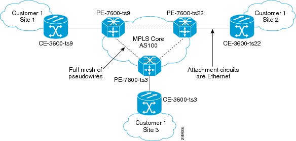
Figure 3-1 shows an example VPLS topology that will be referenced in this section. The three PE devices constitute the neighbors in the VPLS domain. As PEs are added or removed from the domain, VPLS autodiscovery keeps the PE configurations updated.
Figure 3-1 VPLS Autodiscovery Topology Example
To provision VPLS autodiscovery on PE devices in the VPLS domain, you must perform two basic tasks:
•
You must preconfigure some configlets on the devices before they are provisioned by Prime Provisioning. You must do this manually or through the use of templates. See Preconfiguring PE Devices to Support VPLS Autodiscovery.
•
You must enable VPLS autodiscovery within the EVC service request(s) used to provision the PE(s) in the VPLS domain.
The rest of this section documents limitations and restrictions of VPLS autodiscovery, describes the steps you must perform in the workflow to enable it, and provides sample configlets generated on IOS and IOS XR devices.
Limitations and Restrictions for VPLS Autodiscovery
Keep in mind the following limitations and restrictions when using VPLS autodiscovery Prime Provisioning.
•
To use VPLS autodiscovery, all PE devices in the VPLS domain must be have VPLS autodiscovery enabled. Mixed topologies (that is, some PEs configured with VPLS autodiscovery enabled and some without) are not supported. The VPLS discovery mode should be enabled for all service requests under the same virtual forwarding interface (VFI).
•
Some preconfiguration on the PEs in the VPLS domain is required. See Preconfiguring PE Devices to Support VPLS Autodiscovery.
•
Split horizon should be enabled for when using VPLS autodiscovery.
•
VPLS autodiscovery can only be configured in Prime Provisioning using EVC Ethernet service requests for which the MPLS Core Connectivity Type is set as VPLS. The feature is not supported for other Prime Provisioning service requests and/or connectivity types.
•
The same discovery mechanism must be used to build a pseudowire between two PE peers. It is not valid for both auto discovered and manually configured pseudowires in the same VFI to go to the same peer PE. For example, it is not valid for PE1 to be manually configured for PE2 and PE2 be dynamically configured to discover PE1.
•
Once the VPLS discovery mode is provisioned (as manual or autodiscovery) in the service required, it cannot be modified.
•
VPLS autodiscovery is only supported for full-mesh topologies, not hub and spoke topologies like hierarchical VPLS (H-VPLS).
•
VPLS autodiscovery is not supported with inter-autonomous system configurations.
Preconfiguring PE Devices to Support VPLS Autodiscovery
The following configlets must be preconfigured on IOS and IOS XR devices before provisioning VPLS autodiscovery on them. The configlets are required to set up MP-iBGP peering with other PEs and to enable VPLS L2VPN community information exchange with other PEs in the same VPLS domain.
! Setup MP-iBGP peering with other PEs !
no bgp default ipv4-unicast
neighbor 193.193.20.3 remote-as 100
neighbor 193.193.20.3 update-source Loopback0
neighbor 193.193.20.5 remote-as 100
neighbor 193.193.20.5 update-source Loopback0
! Enable VPLS l2vpn community info exchange with other PEs in the same VPLS domain !
address-family l2vpn vpls
neighbor 193.193.20.3 activate
neighbor 193.193.20.3 send-community extended
neighbor 193.193.20.5 activate
neighbor 193.193.20.5 send-community extended
Enabling VPLS Autodiscovery in the EVC Workflow
To enable VPLS discovery in the EVC Ethernet workflow, perform the following steps.
Step 1
In the EVC Ethernet policy or service request workflow, set the MPLS Core Connectivity Type to VPLS.
When the core connectivity is VPLS, the Discovery Mode attribute dynamically appears in the Service Request Details section of the EVC Service Request Editor window. This window describes the VPLS connectivity between the attachment circuits. VPLS connectivity allows the creation of a multipoint connection between two customer sites, using direct connect links or L2 access links.
Step 2
Choose the Discovery Mode type in the EVC Service Request Editor window.
The choices are:
•
Manual— When the Manual option is selected, the vfi command will be configured as in legacy with the manual option. This is the same for both IOS and IOS XR devices. The signaling protocol implemented is LDP.
•
Auto Discovery— When the Auto Discovery option is selected, the vfi command will be configured with the autodiscovery option, and the neighbor command is not required.
For examples of the resulting configlets generated by these choices, see Sample Configlets.
Step 3
Save the service request and deploy it on the device(s) in the VPLS domain.
Sample Configlets
This section provides sample configlets generated by Prime Provisioning for both IOS and IOS XR devices for VPLS autodiscovery.
Sample Configlet for IOS Device
l2 vfi customer1 autodiscovery
! Set attachment circuit interface in VLAN mode !
interface FastEthernet4/1
description VPN for CE9-3640-ts22
switchport access vlan 100
! Bind VLAN100(AC) to the customer1 pseudowire !
Sample Configlet for IOS XR Device
Note
For IOS XR devices, the Route Target value must be saved while creating the VPN.
Policy and Service Request Attributes Reference Tables
This section provides reference information for attributes appearing in windows in EVC Ethernet, EVC ATM-Ethernet Interworking, EVC policies and service requests. To find attributes and descriptions refer to the appropriate section for the service:
•
EVC Ethernet Service Attributes
•
EVC ATM-Ethernet Interworking Service Attributes
•
Sample Configlets
EVC Ethernet Service Attributes
This section describes policy and service request attributes for EVC Ethernet services:
•
EVC Ethernet Policy Attributes
•
EVC Ethernet Service Request Attributes
EVC Ethernet Policy Attributes
•
Service Options Window
•
EVC Attributes Window
•
Interface Attributes Window
Note
Some attributes are supported only on IOS or IOS XR platforms. Attributes apply to both platforms, unless otherwise noted. All platform-specific attributes are visible in the policy workflow windows. Later, when a service request is created based on the policy (and specific devices are associated with the service request), platform-specific attributes are filtered from service request windows, depending on the device type (IOS or IOS XR).
Service Options Window
Table 3-2 describes the attributes in the Service Options window of the EVC Ethernet policy workflow.
Table 3-2 Service Options
Attribute
|
Description
|
CE Directly Connected to EVC
|
Check the box if the CEs are directly connected to the N-PE. Usage notes:
• If the check box is checked, a service request created using this policy can have only directly connected links. No Ethernet access nodes will be involved.
• If the check box is unchecked, a service request created using this policy might or might not have Ethernet access nodes in the links.
• When a CE is directly connected to the N-PE, NPCs are not applicable to the link while creating service requests.
• When a CE is not directly connected to the N-PE, NPCs are used during service request creation, as per standard Prime Provisioning behavior. There is no change in NPC implementation to support EVC functionality.
|
All Links Terminate on EVC
|
Check the box if links need to be configured with EVC features. Usage notes:
• If the check box is checked, a service request created using such policy will have all links using the EVC feature.
• If the check box is unchecked, zero or more links can use the EVC feature. This ensures that existing platforms can still be used in one or more links while delivering the services. This allows the possibility of a link with EVC support being added in the future.
• If the check box is unchecked, in the service request creation process the user must indicate whether or not the created link is EVC or non-EVC.
• If no links are expected to use the EVC feature even in the future (for example, if the provider is not planning to upgrade to the EVC infrastructure for the service that is being created), existing Prime Provisioning policy types (L2VPN or VPLS) can be used instead of EVC.
|
All L2 Access Links default to EVC UNI
|
Check the box to enable EVC syntax configuration on all access devices (U-PE and PE-AGG) throughout the circuit. This shows up in service request as EVC-related attributes for all of these device types. If this attribute is not enabled in the service request, EVC service-related syntax will only be available for N-PE devices.
|
MPLS Core Connectivity Type
|
From the drop-down list, choose the MPLS core connectivity type. The core option supports MPLS only. There is no L2TPv3 support for this service. The choices are:
• PSEUDOWIRE—Choose this option to allow connectivity between two N-PEs across the MPLS core. This option does not limit the service to point-to-point (E-Line). This is because even with the PSEUDOWIRE option selected, there can still be multiple CEs connected to a bridge domain on one or both sides of the pseudowire.
|
|
• LOCAL—Choose this option for local connect cases in which there is no connectivity required across the MPLS core. Local connect supports the following scenarios:
– All interfaces on the N-PE are EVC-capable and using the EVC infrastructure. This is configured by associating all of the customer traffic on these interfaces to a bridge domain. This consumes a VLAN ID on the N-PE (equal to the bridge domain ID).
– Some interfaces on the N-PE are EVC-capable, while others are switch-port-based. In such cases, all of the customer traffic on the interfaces that are configured with the EVC infrastructure are associated to a bridge domain. The traffic on the non-EVC interfaces (and all the access nodes/interfaces beyond this N-PE) are configured with the Service Provider VLAN ID, where the Service Provider VLAN ID is the same as the bridge domain ID for the EVC-based services.
– Only two interfaces on the N-PE are involved, and both are based on EVC-capable line cards. In the first case, the operator might choose not to configure the bridge domain option. In this case, the connect command that is used for the local connects are used, and the global VLAN is conserved on the device. If the operator chooses to configure with the bridge domain option, both interfaces are associated to a bridge domain ID, so that additional local links can be added to the service in future. This consumes a VLAN ID (bridge domain ID) on the N-PE.
|
|
• VPLS—Choose this option to allow connectivity between multiple N-PEs across the MPLS core.
– This includes support for multi-segment pseudowire over an MPLS-TP enabled network. Some or all of the LSPs interconnecting the VPLS instances can be admitted onto existing MPLS-TP tunnels (which may have been provisioned using Prime Provisioning). The LSPs may be configured as multi-segment pseudowires, where each hop can be admitted onto an MPLS-TP tunnel. Prime Provisioning will automatically route the multi-segment pseudowire along the shortest path, taking into consideration any included and/or excluded nodes and/or tunnels.
– The LSP/pseudowire labels may be statically allocated by Prime Provisioning. This eliminates the need for a directed protocol to be run within the VPLS to do label exchange and therefore further eliminates the need for IP connectivity between the endpoints in the VPLS.
– The pool of MPLS labels is shared across VPLS and MPLS-TP services (if they come from the same MPLS static label range on the device). Otherwise Prime Provisioning uses the separate tunnel and service label ranges that are configured on the device. Labels already in use are discovered and removed from the label pool to ensure unique allocation of MPLS labels.
There is no limit on the number of N-PEs across the MPLS core within a service request. However, many service requests can refer to the same customer-associated VPN.
|
Configure With Bridge Domain
|
Check the box to determine bridge domain characteristics. The behavior of the Configure With Bridge-Domain option works in tandem with the choice you selected in the MPLS Core Connectivity Type option, as follows.
• PSEUDOWIRE as the MPLS Core Connectivity Type. There are two cases:
A. With EVC:
– If Configure With Bridge Domain is checked, the policy configures pseudowires under SVIs associated to the bridge domain.
– If Configure With Bridge Domain is unchecked, the policy will configure pseudowires directly under the service instance. This conserves the global VLAN.
B. Without EVC:
– If Configure With Bridge Domain is checked, the policy configures pseudowires as in L2VPN services (with SVIs).
– If Configure With Bridge Domain is unchecked, the policy configures pseudowires directly under subinterfaces.
|
|
Only pseudowires can be either configured directly under service instance of the corresponding EVC-capable interface or under SVIs associated to the bridge domain.
• LOCAL as the MPLS Core Connectivity Type:
– If Configure With Bridge Domain is checked, the policy allows either point-to-point or multipoint local connect services.
– If Configure With Bridge Domain is unchecked, Prime Provisioning allows only point-to-point local connects without bridge domain.
• VPLS—Configure With Bridge Domain is checked by default and non-editable.
When the VPLS service option is selected, VPLS-specific service options appear.
– Check the Static VPLS (AutoPick MPLS Labels) check box to automatically allocate static labels. The static labels are allocated when the service request is saved.
– Check the Configure Pseudowire Segment(s) check box to allow the VPLS service to be admitted onto MPLS-TP tunnels and "stitch" together tunnels to form a simulated end-to-end path.
|
Allow Spoke nodes
|
This attribute is used to enable H-VPLS on EVC VPLS services. It allows the selection of spoke (leaf) nodes in the access of H-VPLS topology. If this check box is enabled, in the service request workflow, the user will be able to set the N-PE as hub or spoke nodes alone. (A spoke node can also be called a "leaf node," which is connected to a hub node).
This attribute only appears if the MPLS Core Connectivity Type is set as VPLS.
|
Allow Spoke with Spoke nodes
|
This attribute can also be used to enable H-VPLS on EVC VPLS services. It allows the selection of interior nodes in the access of H-VPLS topology, which can again be connected with other leaf nodes. Enabling this check box will enable "Allow spokes nodes" (see previous attribute) by default. Because of this, in the service request workflow, the user will be able to set the N-PE as a hub or spoke with additional spoke nodes.
This attribute only appears if the MPLS Core Connectivity Type is set as VPLS.
|
Split Horizon
|
Check the box to enable split horizon with bridge domain. Usage notes:
• The Use Split Horizon attribute is disabled by default.
• The Use Split Horizon attribute can be used only when the Configure With Bridge Domain check box is checked (enabled).
• When Split Horizon is enabled, the bridge domain command in the CLI will be generated with split horizon. When it is disabled, the bridge domain command will be generated without split horizon.
|
Static Pseudowire (Autopick MPLS Labels)
|
Choose a type. The choices are:
• All Dynamic—Labels will be allocated dynamically during provisioning. No static labels will be added into the configlet.
• All Static—Labels will be allocated statically during provisioning. Every segment in a multi-segment pseudowire will have static labels assigned to it on per-segment basis.
• Defaults—Prime Provisioning will automatically determine whether or not to apply static labels based on the core type of the segment. It will do this on a per segment basis. A multi-segment pseudowire over LDP defaults to dynamic pseudowire. Multi-segment pseudowire over MPLS-TP defaults to static pseudowire.
This attribute only supported for MPLS Core Connectivity Types of PSEUDOWIRE or VPLS.
|
Configure Pseudowire Segment(s)
|
Check the box to enable ability to configure pseudowire classes on a per segment basis in the service request based on this policy. Usage notes:
• The Configure Pseudowire Segment(s) attribute is only applicable for MPLS core connectivity types of PSEUDOWIRE and VPLS. With a VPLS core type, the attribute shows up in the Service Options window of the Policy Editor. With a PSEUDOWIRE core type, the attribute shows up in the Interface Attributes window in the block of other pseudowire-related attributes.
• The Configure Pseudowire Segment(s) attribute is used in conjunction with the Static Pseudowire (Autopick MPLS Labels) attribute to configure the individual segments within a multi-segment pseudowire to be either dynamic or static. This allows you to override the default behavior of Prime Provisioning.
• A segment can be a TP tunnel, a TE tunnel, or an LDP (dynamic) core.
• The configuration is done subsequently in the service request based on the policy. When setting up the links in the service request, you can independently assign Pseudowire classes to ends of the segments of multi-segment pseudowires. For information on attaching pseudowire classes to links see Configuring Multi-segment Pseudowires.
• The Configure Pseudowire Segment(s) attribute is not currently supported in EVC ATM-Ethernet Interworking policies and service requests.
|
EVC Attributes Window
Table 3-3 describes the attributes available in the EVC Attributes window of EVC Ethernet policy workflow.
EVC attributes are organized under the following categories:.
•
Service Attributes. The EVC service attributes are the same no matter which MPLS Core Connectivity Type has been selected.
•
VLAN Match Criteria. Prior to the introduction of the EVC capability, service providers could either deploy service-multiplexed services (ERS/ERMS or EVPL/EVCS) or service-bundled services on a single port. Both could not be supported simultaneously due to the limitations in the infrastructure, which only allowed matching the outer-most VLAN tag.
One of the key benefits of EVC support in Prime Provisioning is to provide a flexible means to examine the VLAN tags (up to two levels) of the incoming frames and associate them to appropriate Ethernet Flow Points (EFPs). This allows service providers to deploy simultaneously both the service-multiplexed and service-bundled services on a single port.
•
VLAN Rewrite Criteria. Together with VLAN matching criteria, VLAN rewrite makes the EVC infrastructure very powerful and flexible. The following VLAN rewrite options are supported:
–
Pop one or two tags.
–
Push one or two tags.
–
Translation (1:1, 2:1, 1:2, 2:2).
Be aware of the following considerations when setting the VLAN rewrite criteria attributes:
–
Only one kind of rewrite can be done on every CE-facing EVC link.
–
All VLAN rewrites are done using the symmetric keyword on the ingress traffic (for example, rewrite ingress tag pop 2 symmetric).
–
For any service instance, only one type of rewrite option (pop, push, or translate) is allowed per instance. For example, if pop out is enabled, push inner, push outer, translate inner, and translate outer are not available.
Table 3-3 EVC Attributes
Attribute
|
Description
|
Service Attributes
|
AutoPick Service Instance ID
|
Check the box to specify that the service instance ID will be autogenerated and allocated to the link during service request creation. If the check box is unchecked, while setting the Prime Provisioning link attributes during service request creation, Prime Provisioning will prompt the operator to specify the service instance ID. Usage notes:
• The service instance ID represents an Ethernet Flow Point (EFP) on an interface in the EVC infrastructure. The service instance ID is locally significant to the interface. This ID has to be unique only at the interface level. The ID must be a value from 1 to 8000.
• There are no resource pools available in Prime Provisioning from which to allocate the service instance IDs.
• It is the responsibility of the operator creating the service request to maintain the uniqueness of the ID at the interface level.
|
AutoPick Service Instance Name
|
Check the box to have Prime Provisioning autogenerate a service instance name when you create a service request based on the policy. The autogenerated value is in the following pattern: CustomerName_ServiceRequestJobID. If the check box is unchecked, then you can enter a value during service request creation.
|
Enable PseudoWire Redundancy
|
Check the box to enable pseudowire redundancy (alternative termination device) under certain conditions. Usage notes:
• Enable Pseudo Wire Redundancy is only available if the MPLS Core Connectivity Type was set as PSEUDOWIRE in the Service Options window (see Defining the EVC Ethernet Policy).
• Enabling this feature allows the user to do the following:
– Configure two pseudowires between two direct links, or:
– Add a backup peer such that pseudowires are configured between A-Z and A-Z'. In this case, the terminating links A, Z, and Z' must all be directly connected links. L2 access links are not supported as backup peers.
• See Setting Up Pseudowire Redundancy and a Backup Peers, for more information on using this feature in service requests.
• See "Terminating an Access Ring on Two N-PEs" and, specifically, the section Using N-PE Redundancy in FlexUNI/EVC Service Requests, for notes on how this option can be used.
|
AutoPick VC ID
|
Check the box to have Prime Provisioning autopick the VC ID during service request creation. If this check box is unchecked, the operator will be prompted to specify a VC ID during service request creation. Usage notes:
• This attribute is available only if MPLS Core Connectivity of Type was set as PSEUDOWIRE or VPLS in the Service Options window (see Defining the EVC Ethernet Policy).
• When AutoPick VC ID is checked, Prime Provisioning allocates a VC ID for pseudowires from the Prime Provisioning-managed VC ID resource pool.
• If MPLS Core Connectivity of Type is VPLS, Prime Provisioning allocates the VPLS VPN ID from the Prime Provisioning-managed VC ID resource pool.
|
AutoPick VFI Name
|
Check the box to have Prime Provisioning autopick the virtual forwarding instance (VFI) name during service request creation. If this check box is unchecked, the operator will be prompted to specify a VFI name during service request creation.
The AutoPick VFI Name attribute is only applicable if the MPLS Core Connectivity Type is set as VPLS. For other core types (PSEUDOWIRE and LOCAL), this attribute will not be displayed.
|
AutoPick Bridge Domain/VLAN ID
|
Check the box to have Prime Provisioning autopick the VLAN ID for the service request during service request creation. If this check box is unchecked, the operator will be prompted to specify a VLAN ID during service request creation. Usage notes:
• AutoPick Bridge Domain/VLAN ID consumes a global VLAN ID on the device.
• The bridge domain/VLAN ID is picked from the existing Prime Provisioning VLAN pool. Once the VLAN ID is assigned in the service request, Prime Provisioning makes the VLAN ID unavailable for subsequent service requests.
• In the case of manual VLAN ID allocation, Prime Provisioning does not manage the VLAN ID if the ID lies outside the range of an Prime Provisioning-managed VLAN pool. In this case, the operator must ensure the uniqueness of the ID in the Ethernet access domain. If an operator specifies a VLAN ID that is within the range of an Prime Provisioning-managed VLAN pool and the VLAN ID is already in use in the access domain, Prime Provisioning displays an error message indicating that the VLAN ID is in use.
For additional information on Access VLAN IDs, see Note on Access VLAN IDs.
|
AutoPick Bridge Group Name
|
Check the box to have Prime Provisioning autopick the group name for the service request during service request creation. If this check box is unchecked, the operator will be prompted to specify a group name during service request creation. If the check box is checked, the group name will default to the customer name. This attribute is applicable only for supported IOS XR devices.
|
AutoPick Bridge Domain Name
|
Check the check box to have Prime Provisioning autopick the domain name for the service request during service request creation. Usage notes:
• If this check box is unchecked, the operator will be prompted to specify a domain name during service request creation.
• If the check box is checked, the domain name will default to the following format:
– For pseudowire and local connect core types: ISC-Job-Job_ID, where Job_ID is the service request job ID.
– For VPLS core type: ISC-VPN_Name-VPN_ID, where VPN_Name is the name of the VPLS VPN being used, and VPN_ID is the VPN ID used in the service request.
• This attribute is applicable only for supported IOS XR devices.
|
VLAN Matching Criteria Attributes
|
Both Tags
|
Check the box to enable service requests created with the policy to match both the inner and outer VLAN tags of the incoming frames. If you do not check this check box, service requests created with the policy will match only the outer VLAN tag of the incoming frames. Checking the Both Tags attribute causes the Inner VLAN Ranges attribute (covered in the next steps) to appear in the EVC Attribute window.
|
Inner VLAN Ranges
|
Check the box to enable the range of inner VLAN tags to be specified during service request creation. If the check box is unchecked, the range of inner VLAN tags are not allowed. In this case, the operator must specify discrete VLAN IDs during service request creation.
|
Outer VLAN Ranges
|
Check the box to enable the range of outer VLAN tags to be specified during service request creation. If the check box is unchecked, the range of outer VLAN tags are not allowed. In this case, the operator must specify discrete VLAN IDs during service request creation.
|
AutoPick Outer VLAN
|
Check the box to have Prime Provisioning autopick the outer VLAN ID from a previously created outer VLAN ID resource pool during service request creation. If this check box is unchecked, the operator will be prompted to specify an outer VLAN ID during service request creation. Usage notes:
• Use of the AutoPick Outer VLAN attribute requires that two elements have already been set up in Prime Provisioning. One is an Interface Access Domain, which is a logical element that groups the physical ports of an N-PE device. The other is an EVC Outer VLAN resource pool, which is used by the Interface Access Domain. For instructions on how to set up these elements, see the sections Setting Up Resources, and Resource Pools.
• AutoPick Outer VLAN can be used for interfaces that support EVC functionality.
• AutoPick Outer VLAN consumes a VLAN ID on the interface that supports EVC.
• The bridge domain VLAN ID is picked from the existing Prime Provisioning VLAN pool.
|
VLAN Rewriter Criteria Attributes
|
Pop Outer
|
Check the box to pop the outer VLAN ID tag of the incoming frames that fulfill the match criteria. If this check box is unchecked, the outer tag of the incoming traffic is not popped.
|
Pop Inner
|
Check the check box to pop the inner VLAN ID tag of the incoming frames that fulfill the match-criteria. If this check box is unchecked, the inner tag is not popped. Note that, if Pop Inner is checked, Pop Outer is automatically checked.
|
Push Outer
|
Check the box to impose an outer VLAN ID tag onto the incoming frames that fulfill the match criteria. If this check box is unchecked, no outer tag is imposed on the incoming frames. Usage notes:
• If Push Outer is checked, all service requests created with the policy push a dot1q outer tag on the incoming frames matching the match criteria. When creating the link during service creation, the operator can specify an outer tag with a value from 1 to 4096.
• This attribute is available regardless of the number of tags used in the match criteria. Whether the incoming traffic is double tagged or single tagged, if Push Outer is enabled, all corresponding service requests push an outer tag. All subsequent nodes consider only the outer-most two tags (if EVC-capable) or just one tag (not EVC-capable) and treat the inner-most tags transparently as payload.
• This VLAN ID is not derived from Prime Provisioning-managed VLAN ID pools.
|
Push Inner
|
Check the box to impose an inner VLAN ID tag onto the incoming frames that fulfill the match criteria. This operation pushes both an inner and an outer tag onto the incoming packet, not just an inner tag. If this check box is unchecked, no inner tag is imposed on the incoming frames. Usage notes:
• If Push Inner is checked, all service requests created with the policy push a dot1q inner tag on the incoming frames matching the match criteria. When creating the link during service creation, the operator can specify an inner tag with a value from 1 to 4096.
• If Push Inner is checked, Push Outer is automatically checked.
• This attribute is available regardless of the number of tags used in the match criteria. Regardless of whether the incoming traffic is double tagged or single tagged, if Push Inner is enabled, all corresponding service requests push an inner tag. All subsequent nodes consider only the outer-most two tags (if EVC-capable) or just one tag (not EVC-capable) and treat the inner-most tags transparently as payload.
• This VLAN ID is not derived from Prime Provisioning-managed VLAN ID pools.
|
Translate Outer
|
Check the box to allow the operator to specify a target outer VLAN ID during service request creation. The outer tag of all the incoming frames that fulfill the match criteria are translated to this ID. If the check box is unchecked, no outer tag translation is performed. See Table 3-4.
|
Translate Inner
|
Check the box to allow the operator to specify a target inner VLAN ID during service request creation. The inner tag of all the incoming frames that fulfill the match criteria are translated to this ID. If the check box is unchecked, no inner tag translation is performed. See Table 3-4.
|
Note on Access VLAN IDs
An access VLAN ID is of local significance to the EVC-capable ports. It should not be confused with the global VLANs. This can be visualized as a partitioning of the Ethernet access network beyond the EVC ports into several subEthernet access domains (one each for an EVC-capable port).
However, all the service interfaces on the Ethernet access nodes beyond the EVC ports will have this very same VLAN ID for a link. This ID must be manually specified by the operator when setting the link attributes during service request creation. The operator must ensure the uniqueness of the ID across the EVC-demarcated Ethernet access domain.
These VLAN IDs are not managed by Prime Provisioning by means of locally-significant VLAN pools. But once a VLAN ID is assigned for a link in the service request, Prime Provisioning makes the VLAN unavailable for subsequent service requests within the Ethernet access domain demarcated by the EVC. Likewise, if a manually-specified VLAN is already in use in the access domain delimited by the EVC, Prime Provisioning will display an error message indicating that the new VLAN ID being specified is already in use on the NPC. The operator will be prompted to specify a different VLAN ID, which will be provisioned on the L2 access nodes.
Table 3-4 VLAN Translation Summary Table
Type
|
Match Outer Tag
|
Match Inner Tag
|
Translate Outer Tag
|
Translate Inner Tag
|
Push Outer Tag
|
1:1
|
True
|
N/A
|
Yes
|
No
|
N/A
|
1:2
|
True
|
N/A
|
N/A
|
N/A
|
Yes
|
2:1
|
True
|
True
|
Yes
|
No
|
N/A
|
2:2
|
True
|
True
|
Yes
|
Yes
|
N/A
|
Note
Table 3-4 summarizes the realization of different VLAN translations available in the EVC infrastructure. The second and third columns (Match Outer Tag and Match Inner Tag) refer to policy settings. The last two columns (Translate Outer Tag and Translate Inner Tag) indicate the VLAN translation that occurs on the incoming frames.
Interface Attributes Window
Table 3-5 describes the attributes available in the EVC Attributes window of EVC Ethernet policy workflow. The attributes you can configure in this window are grouped under the following categories:
•
UNI Information
•
VLAN
•
Pseudowire
•
ACL
•
Security
•
UNI Storm Control
•
Protocol
In some cases, checking an attribute causes additional attributes to appear in the GUI.
Note
If the CE is directly connected to an N-PE, only speed, duplex, UNI shutdown, and other generic options are presented. In this case, port security, storm control, L2 protocol tunneling, and other advanced features are not supported due to the current platform limitations. If these features are needed for a service, the service provider must deploy Layer 2 Ethernet access nodes beyond the EVC to support these requirements.
Note
Attributes available in the Interface Attributes window dynamically change based on the choice made for the MPLS Core Connectivity Type (PSEUDOWIRE, LOCAL, or VPLS) in the Service Options window (see Defining the EVC Ethernet Policy). For completeness, all attributes available for the different core types are listed in the table. Attributes apply to all core types, unless otherwise noted.
Table 3-5 Interface Attributes
Attribute
|
Description
|
Standard UNI Port
|
Check the box to enable port security. This is the default. When you uncheck the check box, the port is treated as an uplink with no security features, and the window dynamically changes to eliminate items related to port security.
|
UNI Shutdown
|
Check the box if you want to leave the UNI port shut during service activation, for example, when the service provider wants to deploy a service in the network but wants to activate it at a later time.
|
Keep Alive
|
Check the box to configure keepalives on the UNI port. By default, this check box is unchecked, which causes the command no keepalive to be provisioned on the UNI port. This prevents a CPE from sending keepalive packets to the U-PE, for security purposes. This attribute is editable, in order to support modification on a per-service request basis.
|
Link Media (optional)
|
Enter None, auto-select, rj45, or sfp.
|
Link Speed (optional)
|
Enter None, 10, 100, 1000, Auto, or nonegotiate.
|
Link Duplex (optional)
|
Enter None, Full, Half, or Auto.
|
Encapsulation
|
Choose a type. The choices are:
• DOT1QTRUNK—Configures the UNI as a trunk with 802.1q encapsulation. If the UNI belongs to a directly connected and EVC link, this setting signifies that the incoming frames are 802.1q encapsulated and that they match the VLAN ID configured for the link. This specific topology does not involve a trunk UNI as such.
• DOT1QTUNNEL—Configures the UNI as an 802.1q tunnel (also known as a dot1q tunnel or Q-in-Q) port.
• ACCESS—Configures the UNI as an access port.
|
VLAN Translation
|
Specify the type for this policy by clicking the appropriate radio button. The choices are:
• No—No VLAN translation is performed. (This is the default.)
• 1:1—1:1 VLAN translation. Translates an incoming customer VLAN to another.
• 2:1—2:1 VLAN translation. Converts both inner and outer VLANs to a single VLAN.
• 1:2—1:2 VLAN translation. Pushes one more provider VLAN.
• 2:2—2:2 VLAN translation. Translates both inner and outer VLANs to two other VLANs.
For more details on how VLAN translation is supported in EVC Ethernet services, see the coverage of the VLAN Translation attribute in Managing an EVC Ethernet Service Request.
|
Use PseudoWireClass
|
Check the box to enable the selection of a pseudowire class. Usage notes:
• The pseudowire class name is used for provisioning pw-class commands on IOS and IOS XR devices. See Creating and Modifying Pseudowire Classes for additional information on pseudowire class support.
• If Use PseudoWireClass is checked, an additional attribute, PseudoWireClass, appears in the GUI. Click the Select button of PseudoWireClass attribute to choose a pseudowire class previously created in Prime Provisioning.
• The Use PseudoWireClass attribute is only available if the MPLS core connectivity type was set as PSEUDOWIRE in the Service Options window (see Defining the EVC Ethernet Policy).
|
E-Line Name
|
Specify the point-to-point (p2p) E-line name. Usage notes:
• If no value is specified for the E-Line Name in either the policy or the service request based on the policy, Prime Provisioning autogenerates a default name as follows:
– For PSEUDOWIRE core connectivity type, the format is:
DeviceName--VC_ID
– For LOCAL core connectivity type, the format is:
DeviceName--0--VLAN_ID
If the default name is more than 32 characters, the device names are truncated.
• The E-Line Name attribute is not available if the MPLS core connectivity type was set as VPLS in the Service Options window (see Defining the EVC Ethernet Policy).
• E-Line Name is only applicable for IOS XR devices.
|
Configure Pseudowire Segments(s)
|
Check the box to enable ability to configure pseudowire classes on a per segment basis in the service request based on this policy. Usage notes:
• The Configure Pseudowire Segment(s) attribute is only applicable for MPLS core connectivity types of PSEUDOWIRE and VPLS. With a VPLS core type, the attribute shows up in the Service Options window of the Policy Editor. With a PSEUDOWIRE core type, the attribute shows up in the Interface Attributes window in the block of other pseudowire-related attributes.
• The Configure Pseudowire Segment(s) attribute is used in conjunction with the Static Pseudowire (Autopick MPLS Labels) attribute to configure the individual segments within a multi-segment pseudowire to be either dynamic or static. This allows you to override the default behavior of Prime Provisioning.
• A segment can be a TP tunnel, a TE tunnel, or an LDP (dynamic) core.
• The configuration is done subsequently in the service request based on the policy. When setting up the links in the service request, you can independently assign Pseudowire classes to ends of the segments of multi-segment pseudowires. For information on attaching pseudowire classes to links see Configuring Multi-segment Pseudowires.
• The Configure Pseudowire Segment(s) attribute is not currently supported in EVC ATM-Ethernet Interworking policies and service requests.
|
N-PE Pseudo-wire on SVI
|
Check the box to have Prime Provisioning generate forwarding commands under SVIs (switch virtual interfaces). By default, this check box is not checked. In this case, Prime Provisioning generates forwarding commands under the service instance.
For an EVC link, the attribute N-PE Pseudo-wire on SVI is dependent on the value of the attribute Configure with Bridge Domain (this is available in the policy workflow in the EVC Policy Editor - Service Options window). N-PE Pseudo-wire on SVI, if enabled, will be reflected only when Configure with Bridge Domain is set to true. Otherwise, the service request will not be created with xconnect under SVI, even if N-PE Pseudo-wire on SVI is enabled.
Usage notes:
• Prime Provisioning supports a hybrid configuration for EVC service requests. In a hybrid configuration, the forwarding commands (such as xconnect) for one side of an attachment circuit can be configured under a service instance, and the xconnect configuration for the other side of the attachment circuit can be configured under a switch virtual interface (SVI).
• For examples of these cases, see configlet examples EVC (Pseudowire Core Connectivity, Bridge Domain, Pseudowire on SVI) and EVC (Pseudowire Core Connectivity, no Bridge Domain, no Pseudowire on SVI).
• N-PE Pseudo-wire on SVI is applicable for all connectivity types (PSEUDOWIRE, VPLS, and LOCAL), but a hybrid SVI configuration is possible only for pseudowire connectivity.
• When MPLS Core Connectivity Type is set as VPLS, the N-PE Pseudo-wire on SVI attribute is always enabled in the policy and service request.
• When MPLS Core Connectivity Type is set as LOCAL connectivity type, the N-PE Pseudo-wire on SVI attribute is always disabled in the policy and service request.
• The N-PE Pseudo-wire on SVI attribute is not supported for IOS XR devices. Only subinterfaces are supported on ASR 9000 devices; service instance is not supported. All the xconnect commands are configured on L2 subinterfaces.
• Table 3-6 shows various use cases for hybrid configuration for EVC service requests.
|
Use Existing ACL Name
|
Check the box if you want to assign your own named access list to the port. By default, this check box is not checked and Prime Provisioning automatically assigns a MAC-based ACL on the customer facing UNI port, based on values you enter in UNI MAC addresses (below).
|
Port-Based ACL Name
|
Enter a Port-Based ACL Name (if you checked the Use Existing ACL Name check box).
Prime Provisioning does not create this ACL automatically. The ACL must already exist on the device, or be added as part of a template, before the service request is deployed. Otherwise, deployment will fail.
|
UNI MAC addresses
|
Enter one or more Ethernet MAC addresses. This selection is present only if you uncheck the Use Existing ACL Name check box. Click the Edit button to bring up a pop-up window in which you enter MAC addresses to be allowed or denied on the port. You can also specify a range of addresses by setting a base MAC address and a filtered MAC address.
|
UNI Port Security
|
Check the box if you to want to provision port security-related CLIs to the UNI port by controlling the MAC addresses that are allowed to go through the interface.
• For Maximum Number of MAC address, enter the number of MAC addresses allowed for port security.
• For Aging, enter the length of time the MAC address can stay on the port security table.
• For Violation Action, choose what action will occur when a port security violation is detected:
– PROTECT—Drops packets with unknown source addresses until a sufficient number of secure MAC addresses are removed to drop below the maximum value.
– RESTRICT—Drops packets with unknown source addresses until a sufficient number of secure MAC addresses are removed to drop below the maximum value and causes the Security Violation counter to increment.
– SHUTDOWN—Puts the interface into the error-disabled state immediately and sends an SNMP trap notification.
• In the Secure MAC Addresses field, enter one or more Ethernet MAC addresses.
|
Enable Storm Control
|
Check the box to help prevent the UNI port from being disrupted by a broadcast, multicast, or unicast storm. Enter a threshold value for each type of traffic. The value, which can be specified to two significant digits, represents the percentage of the total available bandwidth of the port. If the threshold of a traffic type is reached, further traffic of that type is suppressed until the incoming traffic falls below the threshold level.
|
Protocol Tunnelling
|
Check the box if you want to define the Layer 2 Bridge Protocol Data Unit (BPDU) frames that can be tunneled over the core to the other end. For each protocol that you choose, enter the shutdown threshold and drop threshold for that protocol:
• Enable cdp—Enable Layer 2 tunnelling on Cisco Discover Protocol (CDP).
• cdp shutdown threshold—Enter the number of packets per second to be received before the interface is shut down.
• cdp drop threshold—Enter the number of packets per second to be received at which point the interface will start dropping CDP packets.
• Enable vtp—Enable Layer 2 tunnelling on VLAN Trunk Protocol (VTP).
• vtp shutdown threshold—Enter the number of packets per second to be received before the interface is shut down.
• vtp drop threshold—Enter the number of packets per second to be received at which point the interface will start dropping VTP packets.
• Enable stp—Enable Layer 2 tunnelling on Spanning Tree Protocol (STP).
• stp shutdown threshold—Enter the number of packets per second to be received before the interface is shut down.
• stp drop threshold—Enter the number of packets per second to be received at which point the interface will start dropping STP packets.
• Recovery Interval—Enter the amount of time, in seconds, to wait before recovering a UNI port.
|
MTU Size
|
Enter the MTU Size in bytes. The maximum transmission unit (MTU) size is configurable and optional. The default size is 9216, and the range is 1500 to 9216. Prime Provisioning does not perform an integrity check for this customized value. If a service request goes to the Failed Deploy state because this size is not accepted, you must adjust the size until the Service Request is deployed. In Cisco Prime Fulfillment 1.0, different platforms support different ranges.
• For the 3750 and 3550 platforms, the MTU range is 1500 to 1546.
• For the Cisco 7600 Ethernet port, the MTU size is always 9216. Even with the same platform and same IOS release, different line cards support the MTU differently. For example, older line cards only take an MTU size of 9216 and newer cards support 1500 to 9216. However, Prime Provisioning uses 9216 in both cases.
• For the Cisco 7600 SVI (interface VLAN), the MTU size is 1500 to 9216.
|
Table 3-6 Use Cases for Hybrid Configuration for EVC Service Requests
Use Bridge Domain
|
EVC
|
N-PE Pseudowire on SVI
|
CLIs Generated
|
True
|
True
|
True
|
• xconnect under VLAN interface.
• Service instance under main interface.
|
True
|
True
|
False
|
• xconnect under service instance.
• Service instance under main interface.
|
False
|
True
|
N/A
|
• xconnect under service instance.
• Service instance under main interface.
|
True
|
False
|
True
|
xconnect under VLAN interface.
|
True
|
False
|
False
|
xconnect under subinterface.
|
False
|
False
|
False
|
xconnect under subinterface.
|
EVC Ethernet Service Request Attributes
This section provides information about attributes available in the EVC Ethernet service request workflow:
•
Table 3-7, "Pseudowire Core Connectivity Attributes," on page 72
•
Table 3-8, "VPLS Core Connectivity Attributes," on page 74
•
Table 3-9, "Local Core Connectivity Attributes," on page 77
•
Table 3-10, "Service Instance Details Attributes," on page 78
•
Table 3-11, "Standard UNI Attributes," on page 83
Table 3-7 Pseudowire Core Connectivity Attributes
Attribute
|
Description
|
Job ID, SR ID
|
These fields are read-only. When the service request is being created for the first time, the fields display a value of NEW. When an existing service request is being modified, the values of the fields indicate the respective IDs that the Prime Provisioning database holds within the editing flow of the service request.
|
Policy
|
This field is read-only. It displays the name of the policy on which the service request is based. Clicking on the read-only policy name displays a list of all the attribute values set within the policy.
|
Select VPN
|
Click to choose a VPN for use with this service request. The Select VPN window appears with the VPNs defined in the system.
The same VPN can be used by service requests with LOCAL and PSEUDOWIRE core types. If a VPN for a service request is used with VPLS core type, the same VPN cannot be used for service requests with LOCAL or PSEUDOWIRE core type.
1. Choose a VPN Name in the Select column.
You may also use the New VPN Details section of the window to create a new VPN "on the fly." This window provides a subset of the usual VPN creation features. Use the supplied fields to name the new VPN. select/create the customer, and so on. For more information about creating VPNs, see Setting Up Logical Inventory.
2. Click Select.
The EVC Service Request Editor window appears with the VPN name displayed.
|
AutoPick VC ID
|
Check the box if you want Prime Provisioning to choose a VC ID. If you do not check this check box, you will be prompted to provide the ID in the VC ID field, as covered in the next step. When AutoPick VC ID is checked, Prime Provisioning allocates a VC ID for pseudowires from the Prime Provisioning-managed VC ID resource pool. In this case, the text field for the VC ID option is non-editable.
|
VC ID
|
If AutoPick VC ID was unchecked, enter a VC ID in the VC ID field. Usage notes:
• The VC ID value must be an integer value corresponding to a VC ID.
• When a VC ID is manually allocated, Prime Provisioning verifies the VC ID to see if it lies within Prime Provisioning's VC ID pool. If the VC ID is in the pool but not allocated, the VC ID is allocated to the service request. If the VC ID is in the pool and is already in use, Prime Provisioning prompts you to allocate a different VC ID. If the VC ID lies outside of the Prime Provisioning VC ID pool, Prime Provisioning does not perform any verification about whether or not the VC ID allocated. The operator must ensure the VC ID is available.
• The VC ID can be entered only while creating a service. If you are editing the service request, the VC ID field is not editable.
|
Enable PseudoWire Redundancy
|
Check the box to enable pseudowire redundancy (alternative termination device) under certain conditions. Usage notes:
• Enable Pseudo Wire Redundancy is only available if the MPLS Core Connectivity Type was set as PSEUDOWIRE in the Service Options window (see Defining the EVC Ethernet Policy).
• Enabling this feature allows the user to do the following:
– Configure two pseudowires between two direct links, or:
– Add a backup peer such that pseudowires are configured between A-Z and A-Z'. In this case, the terminating links A, Z, and Z' must all be directly connected links. L2 access links are not supported as backup peers.
• See Setting Up Pseudowire Redundancy and a Backup Peers, for more information on using this feature in service requests.
• See "Terminating an Access Ring on Two N-PEs" and, specifically, the section Using N-PE Redundancy in FlexUNI/EVC Service Requests, for notes on how this option can be used.
|
Backup PW VC ID
|
If the AutoPick VC ID attribute was unchecked, enter a VC ID for the backup pseudowire in the Backup PW VC ID field. See the usage notes for the AutoPick VC ID attribute above. The backup VC ID behaves the same as the VC ID of the primary pseudowire.
|
Static Pseudowire (Autopick MPLS Labels)
|
Choose a type. The choices are:
• All Dynamic—Labels will be allocated dynamically during provisioning. No static labels will be added into the configlet.
• All Static—Labels will be allocated statically during provisioning. Every segment in a multi-segment pseudowire will have static labels assigned to it on per-segment basis.
• Defaults—Prime Provisioning will automatically determine whether or not to apply static labels based on the core type of the segment. It will do this on a per segment basis. A multi-segment pseudowire over LDP defaults to dynamic pseudowire. Multi-segment pseudowire over MPLS-TP defaults to static pseudowire.
This attribute only supported for MPLS Core Connectivity Types of PSEUDOWIRE or VPLS.
|
Configure Bridge Domain
|
Check the box to determine bridge domain characteristics. The behavior of the Configure Bridge Domain option works in tandem with the choice you selected in the MPLS Core Connectivity Type option in the EVC policy, which in this case is pseudowire core connectivity. There are two cases:
• With EVC:
– If Configure With Bridge Domain is checked, the policy will configure pseudowires under SVIs associated to the bridge domain.
– If Configure With Bridge Domain is unchecked, the policy will configure pseudowires directly under the service instance. This will conserve the global VLAN.
• Without EVC:
– If Configure With Bridge Domain is checked, the policy will configure pseudowires under SVIs.
– If Configure With Bridge Domain is unchecked, the policy will configure pseudowires directly under subinterfaces.
Pseudowires can be configured either directly under service instance of the corresponding EVC-capable interface or under SVIs associated to the bridge domain.
|
Use Split Horizon
|
Check the box to enable split horizon with bridge domain. Usage notes:
• The Use Split Horizon attribute is disabled by default.
• The Use Split Horizon attribute can be used only when the Configure Bridge Domain check box is checked (enabled).
• When Use Split Horizon is enabled, the bridge domain command in the CLI will be generated with split horizon. When it is disabled, the bridge domain command will be generated without split horizon.
|
Description
|
Click the "Click here" link to enter a description label for the service request. This is useful for searching the Prime Provisioning database for the particular service request. A dialogue appears in which you can enter a description.
|
Table 3-8 VPLS Core Connectivity Attributes
Attribute
|
Description
|
Job ID, SR ID
|
These fields are read-only. When the service request is being created for the first time, the fields display a value of NEW. When an existing service request is being modified, the values of the fields indicate the respective IDs that the Prime Provisioning database holds within the editing flow of the service request.
|
Policy
|
This field is read-only. It displays the name of the policy on which the service request is based.
|
Select VPN
|
Click Select VPN to choose a VPN for use with this service request. The Select VPN window appears with the VPNs defined in the system.
The same VPN can be used by service requests with LOCAL and PSEUDOWIRE core types. If a VPN for a service request is used with VPLS core type, the same VPN cannot be used for service requests with LOCAL or PSEUDOWIRE core type. If the same VPN is used among multiple service requests, all having VPLS core type, then all these service requests participate in the same VPLS service.
1. Choose a VPN Name in the Select column.
You may also use the New VPN Details section of the window to create a new VPN "on the fly." This window provides a subset of the usual VPN creation features. Use the supplied fields to name the new VPN. select/create the customer, and so on. For more information about creating VPNs, see Setting Up Logical Inventory.
2. Click Select.
The EVC Service Request Editor window appears with the VPN name displayed.
|
AutoPick VPLS VPN ID
|
Check the box if you want Prime Provisioning to choose a VPLS VPN ID. If you do not check this check box, you will be prompted to provide the VPN ID in the VPLS VPN ID field, as covered in the next step.
• When AutoPick VPLS VPN ID is checked, Prime Provisioning allocates a VPLS VPN ID from the Prime Provisioning-managed VC ID resource pool. In this case, the text field for the VPLS VPN ID option is non-editable.
• If AutoPick VPLS VPN ID is checked and a service request already exists that refers to same VPN object, the VPLS VPN ID of the existing service request is allocated to the new service request.
|
VPLS VPN ID
|
If AutoPick VPLS VPN ID was unchecked, enter a VPLS VPN ID in the VPLS VPN ID field. Usage notes:
• The VPLS VPN ID value must be an integer value corresponding to a VPN ID.
• When a VPLS VPN ID is manually allocated, Prime Provisioning verifies the VPLS VPN ID to see if it lies within Prime Provisioning's VC ID pool. If the VPLS VPN ID is in the pool but not allocated, the VPLS VPN ID is allocated to the service request. If the VPLS VPN ID is in the pool and is already in use, Prime Provisioning prompts you to allocate a different VPLS VPN ID. If the VPLS VPN ID lies outside of the VC ID pool, Prime Provisioning does not perform any verification about whether the VPLS VPN ID allocated. The operator must ensure the VPLS VPN ID is available.
• The VPLS VPN ID can be entered only while creating a service. If you are editing the service request, the VPLS VPN ID field is not editable.
|
AutoPick VFI Name
|
Check the box if you want Prime Provisioning to choose a virtual forwarding instance (VFI) name. If you do not check this check box, you can provide the VFI name in the VFI Name field, as covered in the next step. Usage notes:
• When AutoPick VFI name is checked, Prime Provisioning generates a VFI name in the following format:
VPN name-VC ID
• This attribute is useful when importing an existing service into Prime Provisioning and mapping it to a service request which has been created for this purpose. Manually specifying the VFI name in the service request allows the VFI name to be matched to that of existing service.
|
VFI Name
|
If AutoPick VFI Name was unchecked, enter a VFI name in the VFI Name field.
|
Discovery Mode
|
Choose the type for VPLS autodiscovery. The choices are:
• Manual—Does not provision VPLS autodiscovery on VPLS PE devices configured by the service request. In this case, when a new PE is device is added or removed from the VPLS domain, manual configuration of each neighbor in the VPLS domain is required.
• Auto Discovery—Provisions VPLS autodiscovery on VPLS PE devices configured by the service request. With VPLS autodiscovery enabled, neighbor devices automatically detect when PEs are added or removed from the VPLS domain.
For details on how this feature is supported in Prime Provisioning, device preconfiguration requirements, and limitations, see Provisioning VPLS Autodiscovery on Devices using EVC Service Requests.
|
Static Pseudowire (Autopick MPLS Labels)
|
Choose a type. The choices are:
• All Dynamic—Labels will be allocated dynamically during provisioning. No static labels will be added into the configlet.
• All Static—Labels will be allocated statically during provisioning. Every segment in a multi-segment pseudowire will have static labels assigned to it on per-segment basis.
• Defaults—Prime Provisioning will automatically determine whether or not to apply static labels based on the core type of the segment. It will do this on a per segment basis.
This attribute only supported for MPLS Core Connectivity Types of PSEUDOWIRE or VPLS.
|
Configure Bridge Domain
|
The box is checked by default and cannot be changed. Usage notes:
• For VPLS, all configurations are under the SVI.
• When the EVC feature is used, all configurations are under the SVI and also associated to a bridge domain.
|
Description
|
Click the "Click here" link to enter a description label for the service request. A dialogue appears in which you can enter a description.
|
Table 3-9 Local Core Connectivity Attributes
Attributes
|
Description
|
Job ID, SR ID
|
These fields are read-only. When the service request is being created for the first time, the fields display a value of NEW. When an existing service request is being modified, the values of the fields indicate the respective IDs that the Prime Provisioning database holds within the editing flow of the service request.
|
Policy
|
This field is read-only. It displays the name of the policy on which the service request is based.
|
Select VPN
|
Click Select VPN to choose a VPN for use with this service request. The Select VPN window appears with the VIPs defined in the system.
The same VPN can be used by service requests with LOCAL and PSEUDOWIRE core types. If a VPN for a service request is used with VPLS core type, the same VPN cannot be used for service requests with LOCAL or PSEUDOWIRE core type.
1. Choose a VPN Name in the Select column.
You may also use the New VPN Details section of the window to create a new VPN "on the fly." This window provides a subset of the usual VPN creation features. Use the supplied fields to name the new VPN. select/create the customer, and so on. For more information about creating VIPs, see Setting Up Logical Inventory.
2. Click Select.
The EVC Service Request Editor window appears with the VPN name displayed.
|
Configure Bridge Domain
|
Check the box to determine bridge domain characteristics. Usage notes:
• If Configure Bridge Domain is checked, all links will have the same bridge domain ID allocated from the VLAN pool on the N-PE. All non-EVC links will have the Service Provider VLAN as the bridge domain ID. On the other hand, if no EVC links are added, the Service Provider VLAN will be allocated first and this will be used as the bridge domain ID when EVC links are added.
• If Configure Bridge Domain is unchecked, a maximum of two links that terminate on the same N-PE can be added. (This uses the connect command available in the EVC infrastructure.) See the following comments for details on how Prime Provisioning degenerates the connect name.
Because the device only accepts a maximum of 15 characters for the connect name, the connect name is generated using the following format:
CustomerNameTruncatedToMaxPossibleCharacters_ServiceRequestJobID
For example, if the customer name is North American Customer and the service request job ID is 56345, the degenerated connect name would be NorthAmer_56345.
The CLI generated would be:
connect NorthAmer_56345 GigabitEthernet7/0/5 11 GigabitEthernet7/0/4 18
In this case, 11 and 18 are service instance IDs.
• If the policy setting for Configure Bridge Domain is non-editable, the option in the service request will be read-only.
|
Use Split Horizon
|
Check the box to enable split horizon with bridge domain. Usage notes:
• The Use Split Horizon attribute is disabled by default.
• The Use Split Horizon attribute can be used only when the Configure Bridge Domain check box is checked (enabled).
• When Use Split Horizon is enabled, the bridge domain command in the CLI will be generated with split horizon. When it is disabled, the bridge domain command will be generated without split horizon.
|
Description
|
Click the "Click here" link to enter a description label for the service request. A dialogue appears in which you can enter a description.
|
Table 3-10 Service Instance Details Attributes
Attribute
|
Description
|
Ectopic Service Instance ID
|
Check the box to specify that the service instance ID will be degenerated and allocated to the link during service request creation. If the check box is unchecked, you must specify the service instance ID (see the next step). Usage notes:
• The service instance ID represents an Ethernet Flow Point (EFP) on an interface in the EVC infrastructure. The service instance ID is locally significant to the interface. This ID has to be unique only at the interface level. The ID must be a value from 1 to 8000.
• There are no resource pools available in Prime Provisioning from which to allocate the service instance IDs.
• In the case of a manually provided service instance ID, it is the responsibility of the operator to maintain the uniqueness of the ID at the interface level.
• This attribute is not displayed for IOS XR devices.
|
Service Instance ID
|
If the AutoPick Service Instance ID check box is not checked, enter an appropriate value for the service instance ID in the Service Instance ID field. This attribute is not displayed for IOS XR devices.
|
AutoPick Service Instance Name
|
Check the box to specify that the service instance name will be autogenerated.If the check box is unchecked, you can specify the service instance name (see the next step). Usage notes:
• If the check box is checked, the Service Instance Name text field is disabled.
• The service instance name is autogenerated in the following pattern: CustomerName_ServiceRequestJobID.
• For example configlets, see EVC (AutoPick Service Instance Name), EVC (Pseudowire Core Connectivity, User-Provided Service Instance Name), and EVC (Local Core Connectivity, User-Provided Service Instance Name).
• This attribute is not displayed for IOS XR devices.
|
Service Instance Name
|
If the AutoPick Service Instance Name check box is not checked, enter an appropriate value for the service instance ID in the Service Instance Name field. Usage notes:
• The text string representing the service instance name must be 40 characters or less and contain no spaces. Other special characters are allowed.
• If AutoPick Service Instance Name is unchecked and no service instance name is entered in the text field, then Prime Provisioning does not generate the global ethernet evc evcname command in the device configuration generated by the service request.
|
AutoPick Bridge Domain/VLAN ID
|
Check the box to have Prime Provisioning autopick the VLAN ID for the service request during service request creation. If this check box is unchecked, the you must specify a bridge domain VLAN ID. Usage notes:
• AutoPick Bridge Domain/VLAN ID consumes a global VLAN ID on the device.
• The bridge domain VLAN ID is picked from the existing Prime Provisioning VLAN pool.
|
Bridge Domain/VLAN ID
|
If the AutoPick Bridge Domain/VLAN ID check box is unchecked, enter an appropriate value in the Bridge Domain/VLAN ID field.
This configuration applies in conjunction with the Configure Bridge Domain option in the EVC Service Request Editor window. If the option is not enabled in that window, then AutoPick Bridge Domain/VLAN ID check box is redundant and not required.
When a VLAN ID is manually allocated, Prime Provisioning verifies the VLAN ID to see if it lies within Prime Provisioning's VLAN ID pool. If the VLAN ID is in the pool but not allocated, the VLAN ID is allocated to the service request. If the VLAN ID is in the pool and is already in use, Prime Provisioning prompts you to allocate a different VLAN ID. If the VLAN ID lies outside of the Prime Provisioning VLAN ID pool, Prime Provisioning does not perform any verification about whether the VLAN ID allocated. The operator must ensure the VLAN ID is available.
|
AutoPick Bridge Domain/VLAN ID Secondary N-PE
|
Check the box to have Prime Provisioning autopick the bridge domain VLAN ID for the secondary N-PE of a dual-homed ring during service request creation. If this check box is unchecked, the you must specify a secondary bridge domain VLAN ID for the secondary N-PE. Usage notes:
• This attribute is only applicable in the case of a dual-homed ring (a ring that terminates on two different N-PEs). Prime Provisioning supports having a separate bridge domain VLAN ID for the secondary N-PE.
• In a dual-homed ring, if the two N-PEs are in different access domains, Prime Provisioning allocates the bridge domain VLAN IDs from both primary and secondary N-PE access domains. When both are in the same Access Domain, Prime Provisioning allocates a common VLAN ID from the Access Domain to which these belong.
• AutoPick Bridge Domain/VLAN ID Secondary N-PE consumes a global VLAN ID on the device.
• The bridge domain VLAN ID is picked from the existing Prime Provisioning VLAN pool.
• This attribute is not displayed for IOS XR devices.
|
Bridge Domain/VLAN ID Secondary N-PE
|
If the AutoPick Bridge Domain/VLAN ID Secondary N-PE check box is unchecked, enter an appropriate value in the Bridge Domain/VLAN ID Secondary N-PE field.
|
Match
|
Choose an encapsulation type from the drop-down list. The choices are:
• DOT1Q
• Default
Selecting Default as the match criteria disables the Outer VLAN ID and Outer VLAN Ranges fields on the page. If Default is the CE encapsulation type, Prime Provisioning shows another field for the UNI port type.
|
Match Inner and Outer Tags
|
Check the box to enable service requests created with the policy to match both the inner and outer VLAN tags of the incoming frames. If you do not check this check box, service requests created with the policy will match only the outer VLAN tag of the incoming frames. Checking the Match Inner and Outer Tags attribute causes the Inner VLAN ID and Outer VLAN ID fields (covered in the next steps) to appear.
|
Inner VLAN ID and Outer VLAN ID
|
If the Match Inner and Outer Tags check box is checked, enter the inner and outer VLAN tags in the Inner VLAN ID and Outer VLAN ID fields. Usage notes:
• You can specify single values, single ranges, multiples values, multiple ranges, or combinations of these. Examples:
– 10
– 10, 15,17
– 10-15
– 10-15,17-20
– 10,20-25
• If the Inner VLAN Ranges attribute is set to true in the policy, the Inner VLAN ID field can take a range of inner VLAN tags.
• If the Outer VLAN Ranges attribute is set to true in the policy, the Outer VLAN ID field can take a range of Outer VLAN tags.
|
Outer VLAN ID
|
If the Match Inner and Outer Tags check box is unchecked, enter the outer VLAN tag in the Outer VLAN ID field. Usage notes:
• The VLAN specified in Outer VLAN ID will be provisioned on the rest of the L2 access nodes (if the link has any), including the customer-facing UNI.
• You may also have Prime Provisioning autopick the outer VLAN ID using the AutoPick Outer VLAN attribute.
|
AutoPick Outer VLAN
|
Check the box to have Prime Provisioning autopick the outer VLAN ID from a previously created outer VLAN ID resource pool. If this check box is unchecked, the operator will be prompted to specify an outer VLAN ID. Usage notes:
• Use of the AutoPick Outer VLAN attribute requires that two elements have already been set up in Prime Provisioning. One is an Interface Access Domain, which is a logical element that groups the physical ports of an N-PE device. The other is an EVC Outer VLAN resource pool, which is used by the Interface Access Domain. For instructions on how to set up these elements, see the sections Setting Up Resources, and Resource Pools.
• AutoPick Outer VLAN can be used for interfaces that support EVC functionality
• AutoPick Outer VLAN consumes a VLAN ID on the interface that supports EVC.
• The bridge domain VLAN ID is picked from the existing Prime Provisioning VLAN pool.
|
Rewrite Type
|
Choose a type from the drop-down list. The choices are:
• Pop
• Push
• Translate
The subsequent attributes in the GUI change depending on the choice of Rewrite Type.
|
|
If Pop is the Rewrite Type, two check boxes appear:
a. Check the Pop Outer Tag check box to pop the outer VLAN ID tag of the incoming frames that fulfill the match criteria. If this check box is unchecked, the outer tag of the incoming traffic will not be popped.
b. Check the Pop Inner Tag check box to pop the inner VLAN ID tag of the incoming frames that fulfill the match-criteria. If this check box is unchecked, the inner tag will not be changed.
Note that if Pop Inner Tag is checked, Pop Outer Tag is automatically checked.
|
|
If Push is the Rewrite Type, two text boxes appear:
a. In the text box Outer VLAN ID, enter an outer VLAN ID tag that will be imposed on the incoming frames that fulfill the match criteria. All service requests created with this setting push a dot1q outer tag on the incoming frames matching the match criteria. If a value is not provided, the push operation is ignored and not configured on the device.
b. In the text box Inner VLAN ID, enter an inner VLAN ID tag that will be imposed on the incoming frames that fulfill the match criteria. All service requests created with this setting push a dot1q inner tag on the incoming frames matching the match criteria. The Inner VLAN tag cannot be pushed without an Outer VLAN tag. That is, when pushing an Inner VLAN tag, the Outer VLAN tag also must be defined.
|
|
If Translate is the Rewrite Type, a Translation Type drop-down list appears. The choices available in this list vary depending on the setting of the Match Inner and Outer Tags attribute.
a. If the Match Inner and Outer Tags check box is checked (true), choose a translation type of 1:1, 1:2, 2:1, or 2:2 from the Translation Type drop-down list.
– If you choose 1:1 or 2:1, enter a value in the Outer VLAN ID text box that appears. The outer tag of all the incoming frames that fulfill the match criteria will be translated to this ID.
– If you choose 1:2 or 2:2, enter values in the Outer VLAN ID and Inner VLAN ID text boxes that appear. The outer and inner tags of all the incoming frames that fulfill the match criteria will be translated to these IDs.
b. If the Match Inner and Outer Tags check box is unchecked (false), choose a translation type of 1:1 or 1:2 from the Translation Type drop-down list.
– If you choose 1:1, enter a value in the Outer VLAN ID text box that appears. The outer tag of all the incoming frames that fulfill the match criteria will be translated to this ID.
– If you choose 1:2, enter values in the Outer VLAN ID and Inner VLAN ID text boxes that appear. The outer and inner tags of all the incoming frames that fulfill the match criteria will be translated to these IDs.
|
Table 3-11 Standard UNI Attributes
Attributes
|
Description
|
N-PE/U-PE Information, Interface Name
|
These fields display the PE device and interface name selected in previous steps. These fields are read-only
|
Encapsulation
|
Choose a type from the drop-down list. The choices are:
• DOT1QTRUNK—Configures the UNI as a trunk with 802.1q encapsulation. If the UNI belongs to a directly connected and EVC link, this setting signifies that the incoming frames are 802.1q encapsulated and that they match the VLAN ID configured for the link. This specific topology does not involve a trunk UNI as such.
• DOT1QTUNNEL—Configures the UNI as an 802.1q tunnel (also known as a dot1q tunnel or Q-in-Q) port.
• ACCESS—Configures the UNI as an access port.
This attribute allows you to deploy different types of UNI encapsulation on different links of a service. Usage notes:
• When a U-PE running with IOS is added in the same circuit terminating on an ASR 9000 (functioning in an N-PE role), the all three encapsulation types values will be visible in the drop-down list of the Encapsulation attribute.
• DOT1QTUNNEL is not directly supported for ASR 9000 devices.
• In the case of direct connect links for which EVC is enabled (by checking the EVC check box in the EVC Service Request Editor window), the choices for the Encapsulation type are DOT1Q and DEFAULT.
|
PE/UNI Interface Description
|
Enter a description for the interface, if desired.
|
UNI Shutdown
|
Check the box if you want to leave the UNI port shut during service activation (for example, when the service provider wants to deploy a service in the network but wants to activate it at a later time).
|
VLAN Translation
|
Specify the type of VLAN translation for the service request by clicking the appropriate radio button. The choices are:
• No—No VLAN translation is performed. (This is the default.)
• 1:1—1:1 VLAN translation.
• 2:1—2:1 VLAN translation.
• 1:2—1:2 VLAN translation.
• 2:2—2:2 VLAN translation.
|
|
Usage notes:
• The VLAN Translation attribute does not appear for direct connect links if the EVC check box is enabled. It does appear for the following combinations:
– Direct connect links with EVC check box disabled.
– L2 access nodes with EVC check box enabled or disabled.
• Choosing a selection other than No causes other fields to appear in the GUI, which you can set based on your configuration:
– CE VLAN—Provide a value between 1 and 4096.
– Auto Pick—Check this check box to have Prime Provisioning autopick the outer VLAN from the VLAN resource pool.
– Outer VLAN—If Auto Pick is unchecked, provide a value between 1 and 4096.
– Select where 2:1 or 2:2 translation takes place—Specify the device where the 2;1 or 2:2 VLAN translation will take place. If you choose Auto, the VLAN translation takes place at the device closest to the UNI port.
• VLAN translation, and all standard UNI and port security attributes are applicable for links with L2 access. If the UNI is on an N-PE, these attributes will not appear.
• When the VLAN translation takes place on a U-PE or PE-AGG device, the VLAN translation command is configured on the NNI interface of the selected device. When the VLAN translation takes place on an NP-E, the VLAN translation command is configured on the UNI interface of the device.
• When there are two NNI interfaces in a ring-based environment, VLAN translation is applied for both of these NNI interfaces.
• 1:1 and 2:1 VLAN translations are supported with the same syntax as for non-EVC (switchport-based N-PE syntax) terminating attachment circuits.
|
N-PE Pseudo-wire on SVI
|
Check the box to have Prime Provisioning generate forwarding commands under SVIs (switch virtual interfaces). By default, this check box is not checked. In this case, Prime Provisioning generates forwarding commands under the service instance.
For an EVC link, the attribute N-PE Pseudo-wire on SVI is dependent on the value of the attribute Configure with Bridge Domain (this is available in the service request workflow in the EVC Service Request Editor window). N-PE Pseudo-wire on SVI, if enabled, will be reflected only when Configure with Bridge Domain is set to true. Otherwise, the service request will not be created with xconnect under SVI, even if N-PE Pseudo-wire on SVI is enabled.
|
|
Usage notes:
• For an EVC link, the attribute N-PE Pseudo-wire on SVI is dependent on the value of the attribute Configure with Bridge Domain (in the EVC Service Request Editor window). N-PE Pseudo-wire on SVI, if enabled, will be reflected only when Configure with Bridge Domain is set to true. Otherwise, the service request will not be created with xconnect under SVI, even if N-PE pseudo-wire on SVI is enabled.
• Prime Provisioning supports a hybrid configuration for EVC service requests. In a hybrid configuration, the forwarding commands (such as xconnect) for one side of an attachment circuit can be configured under a service instance, and the xconnect configuration for the other side of the attachment circuit can be configured under a switch virtual interface (SVI).
• N-PE Pseudo-wire on SVI is applicable for all connectivity types (PSEUDOWIRE, VPLS, and LOCAL), but a hybrid SVI configuration is possible only for pseudowire connectivity.
• When MPLS Core Connectivity Type is set as VPLS, the N-PE Pseudo-wire on SVI attribute is always enabled in the policy and service request.
• When MPLS Core Connectivity Type is set as LOCAL connectivity type, the N-PE Pseudo-wire on SVI attribute is always disabled in the policy and service request.
• For examples of these cases, see configlet examples EVC (Pseudowire Core Connectivity, Bridge Domain, Pseudowire on SVI) and EVC (Pseudowire Core Connectivity, no Bridge Domain, no Pseudowire on SVI).
• For additional information on the N-PE Pseudo-wire on SVI attribute, see the corresponding coverage in the EVC policy section in the section Interface Attributes Window.
• The N-PE Pseudo-wire on SVI attribute is not supported for IOS XR devices. All the xconnect commands are configured on L2 subinterfaces.
|
AutoPick Bridge Group Name
|
Check the box to have Prime Provisioning autopick the bridge group name during service request creation. If this check box is unchecked, you are prompted to specify a bridge group name during service request creation (see the next step). Usage notes:
• This attribute only displays for IOS XR devices.
• If the AutoPick Bridge Group Name check box is unchecked, enter an bridge group name in the Bridge Group Name text field.
• The AutoPick Bridge Group Name and Bridge Group Name attributes only appear if Configure Bridge Domain was enabled in the EVC Service Request Editor window earlier in the service request workflow.
|
AutoPick Bridge Domain/VLAN ID
|
Check the box to have Prime Provisioning autopick the VLAN ID during service request creation. If this check box is unchecked, you are prompted to specify a VLAN ID during service request creation (see the next step). Usage notes:
• AutoPick Bridge Domain/VLAN ID consumes a global VLAN ID on the device.
• The bridge domain VLAN ID is picked from the existing Prime Provisioning VLAN pool.
• The AutoPick Bridge Domain/VLAN ID attribute appears for both Cisco 7600 and ASR 9000 devices. It will be displayed only for non-EVC links.
|
Bridge Domain/VLAN ID
|
If the AutoPick Bridge Domain/VLAN ID check box is unchecked, enter an ID number in the Bridge Domain/VLAN ID text field. Usage notes:
• If AutoPick Bridge Domain/VLAN ID is checked, this field is non-editable.
• When a VLAN ID is manually allocated, Prime Provisioning verifies the VLAN ID to see if it lies within Prime Provisioning's VLAN ID pool. If the VLAN ID is in the pool but not allocated, the VLAN ID is allocated to the service request. If the VLAN ID is in the pool and is already in use, Prime Provisioning prompts you to allocate a different VLAN ID. If the VLAN ID lies outside of the Prime Provisioning VLAN ID pool, Prime Provisioning does not perform any verification about whether the VLAN ID allocated. The operator must ensure the VLAN ID is available.
• The Bridge Domain/VLAN ID text field appears for both Cisco 7600 and ASR 9000 devices. It will be displayed only for non-EVC links.
|
AutoPick Bridge Domain Name
|
Check the box to have Prime Provisioning autopick the bridge domain name during service request creation. If this check box is unchecked, you are prompted to specify a bridge domain name during service request creation (see the next step). Usage notes:
• The AutoPick Bridge Domain Name attribute appears only for Cisco ASR 9000 devices.
• The AutoPick Bridge Domain Name attribute only appears if Configure Bridge Domain was enabled in the EVC Service Request Editor window earlier in the service request workflow.
|
Bridge Domain Name
|
If the AutoPick Bridge Domain Name check box is unchecked, enter a bridge domain name in the Bridge Domain Name text field. Usage notes:
• Bridge Domain Name field appears only for Cisco ASR 9000 devices.
• The Bridge Domain Name attribute only appears if Configure Bridge Domain was enabled in the EVC Service Request Editor window earlier in the service request workflow.
|
Use BVI
|
Check the box to select a bridge virtual interface (BVI) to provide pseudowire access into an L3VPN. When the Use BVI check box is checked, the Select BVI Interface attribute appears, which provides a drop-down list of available BV Is configured on the device. Usage notes:
• The Use BVI attribute is only supported for IOS XR devices. (It is equivalent to the N-PE Pseudo-wire on SVI attribute that is supported for IOS devices.)
• Note the following prerequisites for using the Use BVI attribute:
– In order to use this attribute, you must have previously configured L3VPN services on the device.
– Such L3VPN services must have created BVI interfaces. (These interfaces are what provides pseudowire access into the L3VPN.)
– Furthermore, you must have performed a manual Collect config task for the corresponding N-PE devices in Prime Provisioning so that the L2VPN service would be aware of the BVI interfaces that were configured in the L3VPN.
• For example configlets for this feature, see EVC (Pseudowire Core Connectivity, Pseudowire Service with BVI).
|
Use Split Horizon
|
Check the box to enable split horizon with bridge domain. Usage notes:
• The Use Split Horizon attribute is disabled by default.
• The Use Split Horizon attribute can be used only when the Configure Bridge Domain check box is checked (enabled).
• When Use Split Horizon is enabled, the bridge domain command in the CLI will be generated with split horizon. When it is disabled, the bridge domain command will be generated without split horizon.
|
Use PseudoWireClass
|
Check the box to enable the selection of a pseudowire class. This attribute is unchecked by default. Usage notes:
• The pseudowire class name is used for provisioning pw-class commands on IOS and IOS XR devices. See Creating and Modifying Pseudowire Classes for additional information on pseudowire class support.
• If Use PseudoWireClass is checked, an additional attribute, PseudoWireClass, appears in the GUI. Click the Select button of PseudoWireClass attribute to choose a pseudowire class previously created in Prime Provisioning.
• The Use PseudoWireClass attribute is only available if the MPLS core connectivity type was set as PSEUDOWIRE in the Service Options window (see Defining the EVC Ethernet Policy).
• The Use PseudoWireClass and PseudoWireClass attributes only appear if Configure Bridge Domain was not enabled in the EVC Service Request Editor window earlier in the service request workflow.
|
L2VPN Group Name
|
Choose one of the following from the drop-down list:
• ISC
• VPNSC
Usage notes:
• This attribute is used for provisioning the L2VPN group name on IOS XR devices.
• The choices in the drop-down list are derived from a configurable DCPL property. For information about how to define the L2VPN Group Name choices available in the drop-down list, see Defining L2VPN Group Names for IOS XR Devices.
• The L2VPN Group Name attribute is not available if the MPLS core connectivity type was set as VPLS in the Service Options window (see Defining the EVC Ethernet Policy).
• L2VPN Group Name is only applicable for IOS XR devices.
• The L2VPN Group Name attribute only appears if Configure Bridge Domain was not enabled in the EVC Service Request Editor window earlier in the service request workflow.
|
E-Line Name
|
Enter the point-to-point (p2p) E-line name. Usage notes:
• If no value is specified for the E-Line Name, Prime Provisioning autogenerates a default name as follows:
– For PSEUDOWIRE core connectivity type, the format is:
DeviceName--VC_ID
– For LOCAL core connectivity type, the format is:
DeviceName--VLAN_ID
If the default name is more than 32 characters, the device names are truncated.
• The E-Line Name attribute is not available if the MPLS core connectivity type was set as VPLS in the Service Options window (see Defining the EVC Ethernet Policy).
• E-Line Name is only applicable for IOS XR devices.
• The E-Line Name attribute only appears if Configure Bridge Domain was not enabled in the EVC Service Request Editor window earlier in the service request workflow.
|
EVC ATM-Ethernet Interworking Service Attributes
This section describes policy and service request attributes for EVC ATM-Ethernet services:
•
EVC ATM-Ethernet Interworking Policy Attributes
•
EVC ATM-Ethernet Interworking Service Request Attributes
EVC ATM-Ethernet Interworking Policy Attributes
This section provides reference tables for attributes available in the EVC ATM-Ethernet policy workflow:
•
Service Options Window
•
ATM Interface Attributes Window
•
EVC Attributes Window
•
Interface Attributes Window
Note
Some attributes are supported only on IOS or IOS XR platforms. Attributes apply to both platforms, unless otherwise noted. All platform-specific attributes are visible in the policy workflow windows. Later, when a service request is created based on the policy (and specific devices are associated with the service request), platform-specific attributes are filtered from service request windows, depending on the device type (IOS or IOS XR).
Service Options Window
Table 3-12 describes the attributes in the Service Options Window of the EVC ATM-Interworking policy workflow.
Table 3-12 Service Options
Attribute
|
Description
|
CE Directly Connected to EVC
|
Check the box if the CEs are directly connected to the N-PE. This check box is not checked by default. Usage notes:
• If the check box is checked, a service request created using this policy can have only directly connected links. No Ethernet access nodes will be involved.
• If the check box is unchecked, a service request created using this policy might or might not have Ethernet access nodes in the links.
• When a CE is directly connected to the N-PE, NPCs are not applicable to the link while creating service requests.
• When a CE is not directly connected to the N-PE, NPCs are used during service request creation, as per standard Prime Provisioning behavior. There is no change in NPC implementation to support EVC functionality.
|
All Links Terminate on EVC
|
Check the box if all links need to be configured with EVC features. This check box is not check by default. Usage notes:
• If the check box is checked, a service request created using such policy will have all links using the EVC feature.
• If the check box is unchecked, zero or more links can use the EVC feature. This ensures that existing platforms can still be used in one or more links while delivering the services. This allows the possibility of a link with EVC support being added in the future.
• If the check box is unchecked, in the service request creation process the user must indicate whether or not the created link is EVC or non-EVC.
• If no links are expected to use the EVC feature even in the future (for example, if the provider is not planning to upgrade to the EVC infrastructure for the service that is being created), existing Prime Provisioning policy types (L2VPN or VPLS) can be used instead of EVC.
|
All L2 Access Links default to EVC UNI
|
Check the box to enable EVC syntax configuration on all access devices (U-PE and PE-AGG) throughout the circuit. This shows up in service request as EVC-related attributes for all of these device types. If this attribute is not enabled, in the service request EVC service-related syntax will only be available for N-PE devices.
|
MPLS Core Connectivity Type
|
Choose an MPLS core connectivity type from the drop-down list. The core option supports MPLS only. There is no L2TPv3 support for this service. The choices are:
• PSEUDOWIRE—Choose this option to allow connectivity between two N-PEs across the MPLS core. This option does not limit the service to point-to-point (E-Line). This is because even with the PSEUDOWIRE option selected, there can still be multiple CEs connected to a bridge domain on one or both sides of the pseudowire.
• LOCAL—Choose this option for local connect cases in which there is no connectivity required across the MPLS core.
Local connect supports the following scenarios:
– All interfaces on the N-PE are EVC-capable and using the EVC infrastructure. This is configured by associating all of the customer traffic on these interfaces to a bridge domain. This consumes a VLAN ID on the N-PE (equal to the bridge domain ID).
– Some interfaces on the N-PE are EVC-capable, while others are switch-port-based. In such cases, all of the customer traffic on the interfaces that are configured with the EVC infrastructure are associated to a bridge domain. The traffic on the non-EVC interfaces (and all the access nodes/interfaces beyond this N-PE) are configured with the Service Provider VLAN ID, where the Service Provider VLAN ID is the same as the bridge domain ID for the EVC-based services.
– Only two interfaces on the N-PE are involved, and both are based on EVC-capable line cards. In the first case, the operator might choose not to configure the bridge domain option. In this case, the connect command that is used for the local connects are used, and the global VLAN is conserved on the device. If the operator chooses to configure with the bridge domain option, both interfaces are associated to a bridge domain ID, so that additional local links can be added to the service in future. This consumes a VLAN ID (bridge domain ID) on the N-PE.
• VPLS—This option is not supported for EVC ATM-Ethernet Interworking policies and services requests.
|
Configure With Bridge Domain
|
Check the box to determine bridge domain characteristics. The behavior of the Configure With Bridge-Domain option works in tandem with the choice you selected in the MPLS Core Connectivity Type option, as follows.
• PSEUDOWIRE as the MPLS Core Connectivity Type. There are two cases:
A. With EVC:
– If Configure With Bridge Domain is checked, the policy configures pseudowires under SVIs associated to the bridge domain.
– If Configure With Bridge Domain is unchecked, the policy will configure pseudowires directly under the service instance. This conserves the global VLAN.
B. Without EVC:
– If Configure With Bridge Domain is checked, the policy configures pseudowires as in L2VPN services (with SVIs).
– If Configure With Bridge Domain is unchecked, the policy configures pseudowires directly under subinterfaces.
Only pseudowires can be either configured directly under service instance of the corresponding EVC-capable interface or under SVIs associated to the bridge domain.
• LOCAL as the MPLS Core Connectivity Type:
– If Configure With Bridge Domain is checked, the policy allows either point-to-point or multipoint local connect services.
– If Configure With Bridge Domain is unchecked, Prime Provisioning allows only point-to-point local connects without bridge domain.
|
Split Horizon
|
Check the box to enable split horizon with bridge domain. Usage notes:
• The Use Split Horizon attribute is disabled by default.
• The Use Split Horizon attribute can be used only when the Configure With Bridge Domain check box is checked (enabled).
• When Split Horizon is enabled, the bridge domain command in the CLI will be generated with split horizon. When it is disabled, the bridge domain command will be generated without split horizon.
|
Static Pseudowire (Autopick MPLS Labels)
|
Choose a type. The choices are:
• All Dynamic—Labels will be allocated dynamically during provisioning. No static labels will be added into the configlet.
• All Static—Labels will be allocated statically during provisioning. Every segment in a multi-segment pseudowire will have static labels assigned to it on per-segment basis.
• Defaults—Prime Provisioning will automatically determine whether or not to apply static labels based on the core type of the segment. It will do this on a per segment basis.
This attribute only supported for MPLS Core Connectivity Types of PSEUDOWIRE or VPLS.
|
Configure Pseudowire Segments(s)
|
Check the box to enable ability to configure pseudowire classes on a per segment basis in the service request based on this policy. Usage notes:
• The Configure Pseudowire Segment(s) attribute is only applicable for MPLS core connectivity types of PSEUDOWIRE and VPLS. With a VPLS core type, the attribute shows up in the Service Options window of the Policy Editor. With a PSEUDOWIRE core type, the attribute shows up in the Interface Attributes window in the block of other pseudowire-related attributes.
• The Configure Pseudowire Segment(s) attribute is used in conjunction with the Static Pseudowire (Autopick MPLS Labels) attribute to configure the individual segments within a multi-segment pseudowire to be either dynamic or static. This allows you to override the default behavior of Prime Provisioning.
• A segment can be a TP tunnel, a TE tunnel, or an LDP (dynamic) core.
• The configuration is done subsequently in the service request based on the policy. When setting up the links in the service request, you can independently assign Pseudowire classes to ends of the segments of multi-segment pseudowires. For information on attaching pseudowire classes to links.
• The Configure Pseudowire Segment(s) attribute is not currently supported in EVC ATM-Ethernet Interworking policies and service requests.
|
ATM Interface Attributes Window
Table 3-13 describes the attributes in the ATM Interface Attributes Window of the EVC ATM-Interworking policy workflow.
Table 3-13 ATM Interface Attributes
Description
|
Attribute
|
Transport Mode
|
Choose the transport mode from the drop-down list. The choices are:
• VP—Virtual path mode. This is the default.
• VC—Virtual circuit mode.
|
ATM Encapsulation
|
Choose the ATM encapsulation from the drop-down list. The only available option is AAL5SNAP.
|
EVC Attributes Window
Table 3-14 describes the attributes in the EVC Attributes Window of the EVC ATM-Interworking policy workflow. EVC attributes are organized under the following categories:
•
Service Attributes
•
VLAN Match Criteria. Prior to the introduction of the EVC capability, service providers could either deploy service-multiplexed services (ERS/ERMS or EVPL/EVCS) or service-bundled services on a single port. Both could not be supported simultaneously due to the limitations in the infrastructure, which only allowed matching the outer-most VLAN tag.
One of the key benefits of EVC support in Prime Provisioning is to provide a flexible means to examine the VLAN tags (up to two levels) of the incoming frames and associate them to appropriate Ethernet Flow Points (EFPs). This allows service providers to deploy simultaneously both the service-multiplexed and service-bundled services on a single port.
•
VLAN Rewrite Criteria. Together with VLAN matching criteria, VLAN rewrite makes the EVC infrastructure very powerful and flexible. The following VLAN rewrite options are supported:
–
Pop one or two tags.
–
Push one or two tags.
–
Translation (1:1, 2:1, 1:2, 2:2).
Be aware of the following considerations when setting the VLAN rewrite criteria attributes:
–
Only one kind of rewrite can be done on every CE-facing EVC link.
–
All VLAN rewrites are done using the symmetric keyword on the ingress traffic (for example, rewrite ingress tag pop 2 symmetric).
–
For any service instance, only one type of rewrite option (pop, push, or translate) is allowed per instance. For example, if pop out is enabled, push inner, push outer, translate inner, and translate outer are not available.
Table 3-14 EVC Attributes
Description
|
Attribute
|
Service Attributes
|
AutoPick Service Instance ID
|
Check the box to specify that the service instance ID will be autogenerated and allocated to the link during service request creation. If the check box is unchecked, while setting the Prime Provisioning link attributes during service request creation, Prime Provisioning will prompt the operator to specify the service instance ID. Usage notes:
• The service instance ID represents an Ethernet Flow Point (EFP) on an interface in the EVC infrastructure. The service instance ID is locally significant to the interface. This ID has to be unique only at the interface level. The ID must be a value from 1 to 8000.
• There are no resource pools available in Prime Provisioning from which to allocate the service instance IDs.
• It is the responsibility of the operator creating the service request to maintain the uniqueness of the ID at the interface level.
|
AutoPick Service Instance Name
|
Check the box to have Prime Provisioning autogenerate a service instance name when you create a service request based on the policy. The autogenerated value is in the following pattern: CustomerName_ServiceRequestJobID. If the check box is unchecked, then you can enter a value during service request creation.
|
Enable PseudoWire Redundancy
|
Check the box to enable pseudowire redundancy (alternative termination device) under certain conditions. Enable Pseudo Wire Redundancy is only available if the MPLS Core Connectivity Type was set as PSEUDOWIRE in the Service Options window (see Service Options Window).
|
AutoPick VC ID
|
Check the box to have Prime Provisioning autopick the VC ID during service request creation. If this check box is unchecked, the operator will be prompted to specify a VC ID during service request creation. When AutoPick VC ID is checked, Prime Provisioning allocates a VC ID for pseudowires from the Prime Provisioning-managed VC ID resource pool.
|
AutoPick Bridge Domain/VLAN ID
|
Check the box to have Prime Provisioning autopick the VLAN ID for the service request during service request creation. If this check box is unchecked, the operator will be prompted to specify a VLAN ID during service request creation. Usage notes:
• AutoPick Bridge Domain/VLAN ID consumes a global VLAN ID on the device.
• The bridge domain/VLAN ID is picked from the existing Prime Provisioning VLAN pool. Once the VLAN ID is assigned in the service request, Prime Provisioning makes the VLAN ID unavailable for subsequent service requests.
• In the case of manual VLAN ID allocation, Prime Provisioning does not manage the VLAN ID if the ID lies outside the range of an Prime Provisioning-managed VLAN pool. In this case, the operator must ensure the uniqueness of the ID in the Ethernet access domain. If an operator specifies a VLAN ID that is within the range of an Prime Provisioning-managed VLAN pool and the VLAN ID is already in use in the access domain, Prime Provisioning displays an error message indicating that the VLAN ID is in use.
For additional information on Access VLAN IDs, see Note on Access VLAN IDs.
|
VLAN Matching Criteria Attributes
|
Both Tags
|
Check the box to enable service requests created with the policy to match both the inner and outer VLAN tags of the incoming frames. If you do not check this check box, service requests created with the policy will match only the outer VLAN tag of the incoming frames. Checking the Both Tags attribute causes the Inner VLAN Ranges attribute to appear in the EVC Attribute window.
|
Inner VLAN Ranges
|
Check the box to enable the range of inner VLAN tags to be specified during service request creation. If the check box is unchecked, the range of inner VLAN tags are not allowed. In this case, the operator must specify discrete VLAN IDs during service request creation.
|
Outer VLAN Ranges
|
Check the box to enable the range of outer VLAN tags to be specified during service request creation. If the check box is unchecked, the range of outer VLAN tags are not allowed. In this case, the operator must specify discrete VLAN IDs during service request creation.
|
AutoPick Outer VLAN
|
Check the box to have Prime Provisioning autopick the outer VLAN ID from a previously created outer VLAN ID resource pool during service request creation. If this check box is unchecked, the operator will be prompted to specify an outer VLAN ID during service request creation. Usage notes:
• Use of the AutoPick Outer VLAN attribute requires that two elements have already been set up in Prime Provisioning. One is an Interface Access Domain, which is a logical element that groups the physical ports of an N-PE device. The other is an EVC Outer VLAN resource pool, which is used by the Interface Access Domain. For instructions on how to set up these elements, see the sections Setting Up Resources, and Resource Pools.
• AutoPick Outer VLAN can be used for interfaces that support EVC functionality.
• AutoPick Outer VLAN consumes a VLAN ID on the interface that supports EVC.
• The bridge domain VLAN ID is picked from the existing Prime Provisioning VLAN pool.
|
VLAN Rewrite Criteria Attributes
|
Pop Outer
|
Check the box to pop the outer VLAN ID tag of the incoming frames that fulfill the match criteria. If this check box is unchecked, the outer tag of the incoming traffic is not popped.
|
Pop Inner
|
Check the box to pop the inner VLAN ID tag of the incoming frames that fulfill the match-criteria. If this check box is unchecked, the inner tag is not popped. Note that, if Pop Inner is checked, Pop Outer is automatically checked.
|
Push Outer
|
Check the box to impose an outer VLAN ID tag onto the incoming frames that fulfill the match criteria. If this check box is unchecked, no outer tag is imposed on the incoming frames. Usage notes:
• If Push Outer is checked, all service requests created with the policy push a dot1q outer tag on the incoming frames matching the match criteria. When creating the link during service creation, the operator can specify an outer tag with a value from 1 to 4096.
• This attribute is available regardless of the number of tags used in the match criteria. Whether the incoming traffic is double tagged or single tagged, if Push Outer is enabled, all corresponding service requests push an outer tag. All subsequent nodes consider only the outer-most two tags (if EVC-capable) or just one tag (not EVC-capable) and treat the inner-most tags transparently as payload.
• This VLAN ID is not derived from Prime Provisioning-managed VLAN ID pools.
|
Push Inner
|
Check the box to impose an inner VLAN ID tag onto the incoming frames that fulfill the match criteria. This operation pushes both an inner and an outer tag onto the incoming packet, not just an inner tag. If this check box is unchecked, no inner tag is imposed on the incoming frames. Usage notes:
• If Push Inner is checked, all service requests created with the policy push a dot1q inner tag on the incoming frames matching the match criteria. When creating the link during service creation, the operator can specify an inner tag with a value from 1 to 4096.
• If Push Inner is checked, Push Outer is automatically checked.
• This attribute is available regardless of the number of tags used in the match criteria. Regardless of whether the incoming traffic is double tagged or single tagged, if Push Inner is enabled, all corresponding service requests push an inner tag. All subsequent nodes consider only the outer-most two tags (if EVC-capable) or just one tag (not EVC-capable) and treat the inner-most tags transparently as payload.
• This VLAN ID is not derived from Prime Provisioning-managed VLAN ID pools.
|
Translate Outer
|
Check the box to allow the operator to specify a target outer VLAN ID during service request creation. The outer tag of all the incoming frames that fulfill the match criteria are translated to this ID. If the check box is unchecked, no outer tag translation is performed. See Table 3-15.
|
Translate Inner
|
Check the box to allow the operator to specify a target inner VLAN ID during service request creation. The inner tag of all the incoming frames that fulfill the match criteria are translated to this ID. If the check box is unchecked, no inner tag translation is performed. See Table 3-15.
|
Note on Access VLAN IDs
An access VLAN ID is of local significance to the EVC-capable ports. It should not be confused with the global VLANs. This can be visualized as a partitioning of the Ethernet access network beyond the EVC ports into several subEthernet access domains (one each for an EVC-capable port).
However, all the service interfaces on the Ethernet access nodes beyond the EVC ports will have this very same VLAN ID for a link. This ID must be manually specified by the operator when setting the link attributes during service request creation. The operator must ensure the uniqueness of the ID across the EVC-demarcated Ethernet access domain.
These VLAN IDs are not managed by Prime Provisioning by means of locally-significant VLAN pools. But once a VLAN ID is assigned for a link in the service request, Prime Provisioning makes the VLAN unavailable for subsequent service requests within the Ethernet access domain demarcated by the EVC. Likewise, if a manually-specified VLAN is already in use in the access domain delimited by the EVC, Prime Provisioning will display an error message indicating that the new VLAN ID being specified is already in use on the NPC. The operator will be prompted to specify a different VLAN ID, which will be provisioned on the L2 access nodes.
[
Table 3-15 VLAN Translation Summary Table
Type
|
Match Outer Tag
|
Match Inner Tag
|
Translate Outer Tag
|
Translate Inner Tag
|
Push Outer Tag
|
1:1
|
True
|
N/A
|
Yes
|
No
|
N/A
|
1:2
|
True
|
N/A
|
N/A
|
N/A
|
Yes
|
2:1
|
True
|
True
|
Yes
|
No
|
N/A
|
2:2
|
True
|
True
|
Yes
|
Yes
|
N/A
|
Note
Table 3-15 summarizes the realization of different VLAN translations available in the EVC infrastructure. The second and third columns (Match Outer Tag and Match Inner Tag) refer to policy settings. The last two columns (Translate Outer Tag and Translate Inner Tag) indicate the VLAN translation that occurs on the incoming frames.
Interface Attributes Window
Table 3-16 describes the attributes in the Interface Attributes Window of the EVC ATM-Interworking policy workflow. The attributes you can configure in this window are grouped under the following categories:
•
UNI Information
•
VLAN
•
Pseudowire
•
ACL
•
Security
•
UNI Storm Control
•
Protocol
In some cases, checking an attribute causes additional attributes to appear in the GUI. This is covered in the steps that follow.
Note
If the CE is directly connected to an N-PE, only speed, duplex, UNI shutdown, and other generic options are presented. In this case, port security, storm control, L2 protocol tunneling, and other advanced features are not supported due to the current platform limitations. If these features are needed for a service, the service provider must deploy Layer 2 Ethernet access nodes beyond the EVC to support these requirements.
Note
Attributes available in the Interface Attributes window dynamically change based on the choice made for the MPLS Core Connectivity Type (PSEUDOWIRE or LOCAL) in the Service Options window (see Defining the EVC ATM-Ethernet Interworking Policy). For completeness, all attributes available for the different core types are documented in the following steps. Attributes apply to all core types, unless otherwise noted.
Table 3-16 Interface Attributes
Attribute
|
Description
|
Standard UNI Port
|
Check the box to enable port security. This is the default. When you uncheck the check box, the port is treated as an uplink with no security features, and the window dynamically changes to eliminate items related to port security.
When the UNI is configured on an N-PE device running IOS XR, the Standard UNI Port attribute is not supported. All the CLIs related to Standard UNI Port and UNI Port Security are ignored in this case.
|
UNI Shutdown
|
Check the box if you want to leave the UNI port shut during service activation, for example, when the service provider wants to deploy a service in the network but wants to activate it at a later time.
|
Keep Alive
|
Check the box to configure keepalives on the UNI port. By default, this check box is unchecked, which causes the command no keepalive to be provisioned on the UNI port. This prevents a CPE from sending keepalive packets to the U-PE, for security purposes. This attribute is editable, in order to support modification on a per-service request basis.
|
Link Media (optional)
|
Enter None, auto-select, rj45, or sfp.
|
Link Speed (optional)
|
Enter None, 10, 100, 1000, Auto, or nonegotiate.
|
Link Duplex (optional)
|
Enter None, Full, Half, or Auto.
|
Encapsulation
|
Choose a type. The choices are:
• DOT1QTRUNK—Configures the UNI as a trunk with 802.1q encapsulation. If the UNI belongs to a directly connected and EVC link, this setting signifies that the incoming frames are 802.1q encapsulated and that they match the VLAN ID configured for the link. This specific topology does not involve a trunk UNI as such.
• DOT1QTUNNEL—Configures the UNI as an 802.1q tunnel (also known as a dot1q tunnel or Q-in-Q) port.
• ACCESS—Configures the UNI as an access port.
|
VLAN Translation
|
Specify the type for this policy by clicking the appropriate radio button. The choices are:
• No—No VLAN translation is performed. (This is the default.)
• 1:1—1:1 VLAN translation. Translates an incoming customer VLAN to another.
• 2:1—2:1 VLAN translation. Converts both inner and outer VLANs to a single VLAN.
• 1:2—1:2 VLAN translation. Pushes one more provider VLAN.
• 2:2—2:2 VLAN translation. Translates both inner and outer VLANs to two other VLANs.
For more details on how VLAN translation is supported in EVC ATM-Ethernet services, see the coverage of the VLAN Translation attribute in Managing an EVC ATM-Ethernet Interworking Service Request.
|
Use PseudoWireClass
|
Check the box to enable the selection of a pseudowire class. This attribute is unchecked by default. Usage notes:
• The pseudowire class name is used for provisioning pw-class commands on IOS and IOS XR devices. See Creating and Modifying Pseudowire Classes for additional information on pseudowire class support.
• If Use PseudoWireClass is checked, an additional attribute, PseudoWireClass, appears in the GUI. Click the Select button of PseudoWireClass attribute to choose a pseudowire class previously created in Prime Provisioning.
• The Use PseudoWireClass attribute is only available if the MPLS core connectivity type was set as PSEUDOWIRE in the Service Options window (see Defining the EVC ATM-Ethernet Interworking Policy).
|
L2VPN Group Name
|
Choose one of the following from the drop-down list:
• ISC
• VPNSC
Usage notes:
• This attribute is used for provisioning the L2VPN group name on IOS XR devices.
• The choices in the drop-down list are derived from a configurable DCPL property. For information about how to define the L2VPN Group Name choices available in the drop-down list, see Defining L2VPN Group Names for IOS XR Devices.
• L2VPN Group Name is only applicable for IOS XR devices.
|
E-Line Name
|
Specify the point-to-point (p2p) E-line name. Usage notes:
• If no value is specified for the E-Line Name in either the policy or the service request based on the policy, Prime Provisioning autogenerates a default name as follows:
– For PSEUDOWIRE core connectivity type, the format is:
DeviceName--VC_ID
– For LOCAL core connectivity type, the format is:
DeviceName--VLAN_ID
If the default name is more than 32 characters, the device names are truncated.
• E-Line Name is only applicable for IOS XR devices.
|
N-PE Pseudo-wire on SVI
|
Check the box to have Prime Provisioning generate forwarding commands under SVIs (switch virtual interfaces). By default, this check box is not checked. In this case, Prime Provisioning generates forwarding commands under the service instance.
For an EVC link, the attribute N-PE Pseudo-wire on SVI is dependent on the value of the attribute Configure with Bridge Domain (this is available in the policy workflow in the EVC Policy Editor - Service Options window). N-PE Pseudo-wire on SVI, if enabled, will be reflected only when Configure with Bridge Domain is set to true. Otherwise, the service request will not be created with xconnect under SVI, even if N-PE Pseudo-wire on SVI is enabled.
Usage notes:
• Prime Provisioning supports a hybrid configuration for EVC service requests. In a hybrid configuration, the forwarding commands (such as xconnect) for one side of an attachment circuit can be configured under a service instance, and the xconnect configuration for the other side of the attachment circuit can be configured under a switch virtual interface (SVI).
• For examples of these cases, see configlet examples EVC (Pseudowire Core Connectivity, Bridge Domain, Pseudowire on SVI) and EVC (Pseudowire Core Connectivity, no Bridge Domain, no Pseudowire on SVI).
• N-PE Pseudo-wire on SVI is applicable for all connectivity types, but a hybrid SVI configuration is possible only for pseudowire connectivity.
• When MPLS Core Connectivity Type is set as LOCAL connectivity type, the N-PE Pseudo-wire on SVI attribute is always disabled in the policy and service request.
• The N-PE Pseudo-wire on SVI attribute is not supported for IOS XR devices. All the xconnect commands are configured on L2 subinterfaces/service instance.
• Table 3-17 shows various use cases for hybrid configuration for EVC service requests. [Move outside table]
|
Use Existing ACL Name
|
Check the box if you want to assign your own named access list to the port. By default, this check box is not checked and Prime Provisioning automatically assigns a MAC-based ACL on the customer facing UNI port, based on values you enter in UNI MAC addresses.
|
Port-Based ACL Name
|
Enter a Port-Based ACL Name (if you checked the Use Existing ACL Name check box).
Prime Provisioning does not create this ACL automatically. The ACL must already exist on the device, or be added as part of a template, before the service request is deployed. Otherwise, deployment will fail.
|
UNI MAC addresses
|
Enter one or more Ethernet MAC addresses. This selection is present only if you uncheck the Use Existing ACL Name check box. Click the Edit button to bring up a pop-up window in which you enter MAC addresses to be allowed or denied on the port. You can also specify a range of addresses by setting a base MAC address and a filtered MAC address.
|
UNI Port Security
|
Check the box if you to want to provision port security-related CLIs to the UNI port by controlling the MAC addresses that are allowed to go through the interface.
• For Maximum Number of MAC address, enter the number of MAC addresses allowed for port security.
• For Aging, enter the length of time the MAC address can stay on the port security table.
• For Violation Action, choose what action will occur when a port security violation is detected:
– PROTECT—Drops packets with unknown source addresses until a sufficient number of secure MAC addresses are removed to drop below the maximum value.
– RESTRICT—Drops packets with unknown source addresses until a sufficient number of secure MAC addresses are removed to drop below the maximum value and causes the Security Violation counter to increment.
– SHUTDOWN—Puts the interface into the error-disabled state immediately and sends an SNMP trap notification.
• In the Secure MAC Addresses field, enter one or more Ethernet MAC addresses.
|
Enable Storm Control
|
Check the box to help prevent the UNI port from being disrupted by a broadcast, multicast, or unicast storm. Enter a threshold value for each type of traffic. The value, which can be specified to two significant digits, represents the percentage of the total available bandwidth of the port. If the threshold of a traffic type is reached, further traffic of that type is suppressed until the incoming traffic falls below the threshold level.
|
Protocol Tunnelling
|
Check the box if you want to define the Layer 2 Bridge Protocol Data Unit (BPDU) frames that can be tunneled over the core to the other end. For each protocol that you choose, enter the shutdown threshold and drop threshold for that protocol:
• Enable cdp—Enable Layer 2 tunnelling on Cisco Discover Protocol (CDP).
• cdp shutdown threshold—Enter the number of packets per second to be received before the interface is shut down.
• cdp drop threshold—Enter the number of packets per second to be received at which point the interface will start dropping CDP packets.
• Enable vtp—Enable Layer 2 tunnelling on VLAN Trunk Protocol (VTP).
• vtp shutdown threshold—Enter the number of packets per second to be received before the interface is shut down.
• vtp drop threshold—Enter the number of packets per second to be received at which point the interface will start dropping VTP packets.
• Enable stp—Enable Layer 2 tunnelling on Spanning Tree Protocol (STP).
• stp shutdown threshold—Enter the number of packets per second to be received before the interface is shut down.
• stp drop threshold—Enter the number of packets per second to be received at which point the interface will start dropping STP packets.
• Recovery Interval—Enter the amount of time, in seconds, to wait before recovering a UNI port.
|
MTU Size
|
Enter the MTU size in bytes. The maximum transmission unit (MTU) size is configurable and optional. The default size is 9216, and the range is 1500 to 9216. Prime Provisioning does not perform an integrity check for this customized value. If a service request goes to the Failed Deploy state because this size is not accepted, you must adjust the size until the Service Request is deployed.
In Cisco Prime Provisioning 6.3, different platforms support different ranges.
• For the 3750 and 3550 platforms, the MTU range is 1500 to 1546.
• For the Cisco 7600 Ethernet port, the MTU size is always 9216. Even with the same platform and same IOS release, different line cards support the MTU differently. For example, older line cards only take an MTU size of 9216 and newer cards support 1500 to 9216. However, Cisco Prime Provisioning 6.3 uses 9216 in both cases.
• For the Cisco 7600 SVI (interface VLAN), the MTU size is 1500 to 9216.
|
Table 3-17 Use Cases for Hybrid Configuration for EVC Service Requests
Use Bridge Domain
|
EVC
|
N-PE Pseudowire on SVI
|
CLIs Generated
|
True
|
True
|
True
|
• xconnect under VLAN interface.
• Service instance under main interface.
|
True
|
True
|
False
|
• xconnect under service instance.
• Service instance under main interface.
|
False
|
True
|
N/A
|
• xconnect under service instance.
• Service instance under main interface.
|
True
|
False
|
True
|
xconnect under VLAN interface.
|
True
|
False
|
False
|
xconnect under subinterface.
|
False
|
False
|
False
|
xconnect under subinterface.
|
EVC ATM-Ethernet Interworking Service Request Attributes
This section describes attributes available in the EVC ATM-Ethernet Interworking service request workflow:
•
Table 3-18, "Pseudowire Core Connectivity Attributes," on page 102
•
Table 3-19, "Local Core Connectivity Attributes," on page 104
•
Table 3-20, "Service Instance Details Attributes," on page 105
•
Table 3-21, "Standard UNI Attributes," on page 109
•
Table 3-22, "ATM UNI Attributes," on page 113
Table 3-18 Pseudowire Core Connectivity Attributes
Attribute
|
Description
|
Job ID, SR ID
|
These fields are read-only. When the service request is being created for the first time, the fields display a value of NEW. When an existing service request is being modified, the values of the fields indicate the respective IDs that the Prime Provisioning database holds within the editing flow of the service request.
|
Policy
|
This field is read-only. It displays the name of the policy on which the service request is based. Clicking on the read-only policy name displays a list of all the attribute values set within the policy.
|
Select VPN
|
Click to choose a VPN for use with this service request. The Select VPN window appears with the VPNs defined in the system.
The same VPN can be used by service requests with LOCAL and PSEUDOWIRE core types. If a VPN for a service request is used with VPLS core type, the same VPN cannot be used for service requests with LOCAL or PSEUDOWIRE core type.
1. Choose a VPN Name in the Select column.
You may also use the New VPN Details section of the window to create a new VPN "on the fly." This window provides a subset of the usual VPN creation features. Use the supplied fields to name the new VPN. select/create the customer, and so on. For more information about creating VPNs, see Setting Up Logical Inventory.
2. Click Select.
The EVC Service Request Editor window appears with the VPN name displayed.
|
AutoPick VC ID
|
Check the box if you want Prime Provisioning to choose a VC ID. If you do not check this check box, you will be prompted to provide the ID in the VC ID field, as covered in the next step. When AutoPick VC ID is checked, Prime Provisioning allocates a VC ID for pseudowires from the Prime Provisioning-managed VC ID resource pool. In this case, the text field for the VC ID option is non-editable.
|
VC ID
|
If AutoPick VC ID was unchecked, enter a VC ID in the VC ID field. Usage notes:
• The AutoPick VC ID attribute appears during the creation of an EVC pseudowire service request.
• The VC ID value must be an integer value corresponding to a VC ID.
• When a VC ID is manually allocated, Prime Provisioning verifies the VC ID to see if it lies within Prime Provisioning's VC ID pool. If the VC ID is in the pool but not allocated, the VC ID is allocated to the service request. If the VC ID is in the pool and is already in use, Prime Provisioning prompts you to allocate a different VC ID. If the VC ID lies outside of the Prime Provisioning VC ID pool, Prime Provisioning does not perform any verification about whether or not the VC ID allocated. The operator must ensure the VC ID is available.
• The VC ID can be entered only while creating a service. If you are editing the service request, the VC ID field is not editable.
|
Static Pseudowire (Autopick MPLS Labels)
|
Choose a type. The choices are:
• All Dynamic—Labels will be allocated dynamically during provisioning. No static labels will be added into the configlet.
• All Static—Labels will be allocated statically during provisioning. Every segment in a multi-segment pseudowire will have static labels assigned to it on per-segment basis.
• Defaults—Prime Provisioning will automatically determine whether or not to apply static labels based on the core type of the segment. It will do this on a per segment basis.
This attribute only supported for MPLS Core Connectivity Types of PSEUDOWIRE or VPLS.
|
Configure Bridge Domain
|
Check the box to determine bridge domain characteristics. The behavior of the Configure Bridge Domain option works in tandem with the choice you selected in the MPLS Core Connectivity Type option in the EVC policy, which in this case is pseudowire core connectivity. There are two cases:
• With EVC:
– If Configure With Bridge Domain is checked, the policy will configure pseudowires under SVIs associated to the bridge domain.
– If Configure With Bridge Domain is unchecked, the policy will configure pseudowires directly under the service instance. This will conserve the global VLAN.
• Without EVC:
– If Configure With Bridge Domain is checked, the policy will configure pseudowires under SVIs.
– If Configure With Bridge Domain is unchecked, the policy will configure pseudowires directly under subinterfaces.
Pseudowires can be configured either directly under service instance of the corresponding EVC-capable interface or under SVIs associated to the bridge domain.
|
Use Split Horizon
|
Check the box to enable split horizon with bridge domain. Usage notes:
• The Use Split Horizon attribute is disabled by default.
• The Use Split Horizon attribute can be used only when the Configure Bridge Domain check box is checked (enabled).
• When Use Split Horizon is enabled, the bridge domain command in the CLI will be generated with split horizon. When it is disabled, the bridge domain command will be generated without split horizon.
|
Description
|
Click the "Click here" link to enter a description label for the service request. This is useful for searching the Prime Provisioning database for the particular service request.
|
Table 3-19 Local Core Connectivity Attributes
Attribute
|
Description
|
Job ID, SR ID
|
These fields are read-only. When the service request is being created for the first time, the fields display a value of NEW. When an existing service request is being modified, the values of the fields indicate the respective IDs that the Prime Provisioning database holds within the editing flow of the service request.
|
Policy
|
This field is read-only. It displays the name of the policy on which the service request is based.
|
Select VPN
|
Click to choose a VPN for use with this service request. The Select VPN window appears with the VPNs defined in the system.
The same VPN can be used by service requests with LOCAL and PSEUDOWIRE core types. If a VPN for a service request is used with VPLS core type, the same VPN cannot be used for service requests with LOCAL or PSEUDOWIRE core type.
1. Choose a VPN Name in the Select column.
You may also use the New VPN Details section of the window to create a new VPN "on the fly." This window provides a subset of the usual VPN creation features. Use the supplied fields to name the new VPN. select/create the customer, and so on. For more information about creating VPNs, see Setting Up Logical Inventory.
2. Click Select.
The EVC Service Request Editor window appears with the VPN name displayed.
|
Configure Bridge Domain
|
Check the box to determine bridge domain characteristics. Usage notes:
• If Configure Bridge Domain is checked, all links will have the same bridge domain ID allocated from the VLAN pool on the N-PE. All non-EVC links will have the Service Provider VLAN as the bridge domain ID. On the other hand, if no EVC links are added, the Service Provider VLAN will be allocated first and this will be used as the bridge domain ID when EVC links are added.
• If Configure Bridge Domain is unchecked, a maximum of two links that terminate on the same N-PE can be added. (This uses the connect command available in the EVC infrastructure.) This is only supported for ATM-ATM local connect.
• See the following comments for details on how Prime Provisioning autogenerates the connect name.
Because the device only accepts a maximum of 15 characters for the connect name, the connect name is generated using the following format:
CustomerNameTruncatedToMaxPossibleCharacters_ServiceRequestJobID
For example, if the customer name is NorthAmericanCustomer and the service request job ID is 56345, the autogenerated connect name would be NorthAmer_56345.
The CLI generated would be:
connect NorthAmer_56345 ATM7/0/5 11 ATM7/0/4 18
In this case, 11 and 18 are service instance VPIs.
• If the policy setting for Configure Bridge Domain is non-editable, the option in the service request will be read-only.
|
Use Split Horizon
|
Check the box to enable split horizon with bridge domain. Usage notes:
• The Use Split Horizon attribute is disabled by default.
• The Use Split Horizon attribute can be used only when the Configure Bridge Domain check box is checked (enabled).
• When Use Split Horizon is enabled, the bridge domain command in the CLI will be generated with split horizon. When it is disabled, the bridge domain command will be generated without split horizon.
|
Description
|
Click the "Click here" link to enter a description label for the service request. A dialogue appears in which you can enter a description.
|
Table 3-20 Service Instance Details Attributes
Attribute
|
Description
|
AutoPick Service Instance ID
|
Check the box to specify that the service instance ID will be autogenerated and allocated to the link during service request creation. If the check box is unchecked, you must specify the service instance ID. Usage notes:
• The service instance ID represents an Ethernet Flow Point (EFP) on an interface in the EVC infrastructure. The service instance ID is locally significant to the interface. This ID has to be unique only at the interface level. The ID must be a value from 1 to 8000.
• There are no resource pools available in Prime Provisioning from which to allocate the service instance IDs.
• In the case of a manually provided service instance ID, it is the responsibility of the operator to maintain the uniqueness of the ID at the interface level.
• This attribute is not displayed for IOS XR devices.
|
Service Instance ID
|
If the AutoPick Service Instance ID check box is not checked, enter an appropriate value for the service instance ID in the Service Instance ID field.
|
AutoPick Service Instance Name
|
Check the box to specify that the service instance name will be autogenerated. If the check box is unchecked, you can specify the service instance name. Usage notes:
• If the check box is checked, the Service Instance Name text field is disabled.
• The service instance name is autogenerated in the following pattern: CustomerName_ServiceRequestJobID.
• For example configlets, see EVC (No AutoPick Service Instance Name, No Service Instance Name), EVC (Pseudowire Core Connectivity, User-Provided Service Instance Name), and EVC (Local Core Connectivity, User-Provided Service Instance Name).
• This attribute is not displayed for IOS XR devices.
|
Service Instance Name
|
If the AutoPick Service Instance Name check box is not checked, enter an appropriate value for the service instance ID in the Service Instance Name field. Usage notes:
• The text string representing the service instance name must be 40 characters or less and contain no spaces. Other special characters are allowed.
• If AutoPick Service Instance Name is unchecked and no service instance name is entered in the text field, then Prime Provisioning does not generate the global ethernet evc evcname command in the device configuration generated by the service request.
|
AutoPick Bridge Domain/VLAN ID
|
Check the box to have Prime Provisioning autopick the VLAN ID for the service request during service request creation. If this check box is unchecked, the you must specify a bridge domain VLAN ID. Usage notes:
• AutoPick Bridge Domain/VLAN ID consumes a global VLAN ID on the device.
• The bridge domain VLAN ID is picked from the existing Prime Provisioning VLAN pool.
• This attribute is not displayed for IOS XR devices.
|
Bridge Domain/VLAN ID
|
If the AutoPick Bridge Domain/VLAN ID check box is unchecked, enter an appropriate value in the Bridge Domain/VLAN ID field.
This configuration applies in conjunction with the Configure Bridge Domain option in the EVC Service Request Editor window. If the option is not enabled in that window, then AutoPick Bridge Domain/VLAN ID check box is redundant and not required.
When a VLAN ID is manually allocated, Prime Provisioning verifies the VLAN ID to see if it lies within Prime Provisioning's VLAN ID pool. If the VLAN ID is in the pool but not allocated, the VLAN ID is allocated to the service request. If the VLAN ID is in the pool and is already in use, Prime Provisioning prompts you to allocate a different VLAN ID. If the VLAN ID lies outside of the Prime Provisioning VLAN ID pool, Prime Provisioning does not perform any verification about whether the VLAN ID allocated. The operator must ensure the VLAN ID is available.
|
AutoPick Bridge Domain/VLAN ID Secondary N-PE
|
Check the box to have Prime Provisioning autopick the bridge domain VLAN ID for the secondary N-PE of a dual-homed ring during service request creation. If this check box is unchecked, the you must specify a secondary bridge domain VLAN ID for the secondary N-PE. Usage notes:
• This attribute is only applicable in the case of a dual-homed ring (a ring that terminates on two different N-PEs). Prime Provisioning supports having a separate bridge domain VLAN ID for the secondary N-PE.
• In a dual-homed ring, if the two N-PEs are in different access domains, Prime Provisioning allocates the bridge domain VLAN IDs from both primary and secondary N-PE access domains. When both are in the same Access Domain, Prime Provisioning allocates a common VLAN ID from the Access Domain to which these belong.
• AutoPick Bridge Domain/VLAN ID Secondary N-PE consumes a global VLAN ID on the device.
• The bridge domain VLAN ID is picked from the existing Prime Provisioning VLAN pool.
• This attribute is not displayed for IOS XR devices.
|
Bridge Domain/VLAN ID Secondary N-PE
|
If the AutoPick Bridge Domain/VLAN ID Secondary N-PE check box is unchecked, enter an appropriate value in the Bridge Domain/VLAN ID Secondary N-PE field.
|
Match Inner and Outer Tags
|
Check the box to enable service requests created with the policy to match both the inner and outer VLAN tags of the incoming frames. If you do not check this check box, service requests created with the policy will match only the outer VLAN tag of the incoming frames. Checking the Match Inner and Outer Tags attribute causes the Inner VLAN ID and Outer VLAN ID fields (covered in the next steps) to appear.
|
Match Inner and Outer Tags
|
Check the box to enter the inner and outer VLAN tags in the Inner VLAN ID and Outer VLAN ID fields. Usage notes:
• You can specify single values, single ranges, multiples values, multiple ranges, or combinations of these. Examples:
– 10
– 10, 15,17
– 10-15
– 10-15,17-20
– 10,20-25
• If the Inner VLAN Ranges attribute is set to true in the policy, the Inner VLAN ID field can take a range of inner VLAN tags.
• If the Outer VLAN Ranges attribute is set to true in the policy, the Outer VLAN ID field can take a range of Outer VLAN tags.
|
Outer VLAN ID
|
If the Match Inner and Outer Tags check box is unchecked, enter the outer VLAN tag in the Outer VLAN ID field.
• The VLAN specified in Outer VLAN ID will be provisioned on the rest of the L2 access nodes (if the link has any), including the customer-facing UNI.
• You may also have Prime Provisioning autopick the outer VLAN ID.
|
AutoPick Outer VLAN
|
Check the box to have Prime Provisioning autopick the outer VLAN ID from a previously created outer VLAN ID resource pool. If this check box is unchecked, the operator will be prompted to specify an outer VLAN ID. Usage notes:
• Use of the AutoPick Outer VLAN attribute requires that two elements have already been set up in Prime Provisioning. One is an Interface Access Domain, which is a logical element that groups the physical ports of an N-PE device. The other is an EVC Outer VLAN resource pool, which is used by the Interface Access Domain. For instructions on how to set up these elements, see the sections Setting Up Resources, and Resource Pools.
• AutoPick Outer VLAN can be used for interfaces that support EVC functionality
• AutoPick Outer VLAN consumes a VLAN ID on the interface that supports EVC.
• The bridge domain VLAN ID is picked from the existing Prime Provisioning VLAN pool.
|
Rewrite Type
|
Choose a type from the drop-down list. The choices are:
• Pop
• Push
• Translate
The subsequent attributes in the GUI change depending on the choice of Rewrite Type, as covered in the next steps.
If Pop is the Rewrite Type, two check boxes appear:
a. Check the Pop Outer Tag check box to pop the outer VLAN ID tag of the incoming frames that fulfill the match criteria. If this check box is unchecked, the outer tag of the incoming traffic will not be popped.
b. Check the Pop Inner Tag check box to pop the inner VLAN ID tag of the incoming frames that fulfill the match-criteria. If this check box is unchecked, the inner tag will not be changed.
Note that if Pop Inner Tag is checked, Pop Outer Tag is automatically checked.
If Push is the Rewrite Type, two text boxes appear:
a. In the text box Outer VLAN ID, enter an outer VLAN ID tag that will be imposed on the incoming frames that fulfill the match criteria. All service requests created with this setting push a dot1q outer tag on the incoming frames matching the match criteria. If a value is not provided, the push operation is ignored and not configured on the device.
b. In the text box Inner VLAN ID, enter an inner VLAN ID tag that will be imposed on the incoming frames that fulfill the match criteria. All service requests created with this setting push a dot1q inner tag on the incoming frames matching the match criteria. The Inner VLAN tag cannot be pushed without an Outer VLAN tag. That is, when pushing an Inner VLAN tag, the Outer VLAN tag also must be defined.
|
|
If Translate is the Rewrite Type, a Translation Type drop-down list appears. The choices available in this list vary depending on the setting of the Match Inner and Outer Tags attribute (set in a previous step).
a. If the Match Inner and Outer Tags check box is checked (true), choose a translation type of 1:1, 1:2, 2:1, or 2:2 from the Translation Type drop-down list.
– If you choose 1:1 or 2:1, enter a value in the Outer VLAN ID text box that appears. The outer tag of all the incoming frames that fulfill the match criteria will be translated to this ID.
– If you choose 1:2 or 2:2, enter values in the Outer VLAN ID and Inner VLAN ID text boxes that appear. The outer and inner tags of all the incoming frames that fulfill the match criteria will be translated to these IDs.
b. If the Match Inner and Outer Tags check box is unchecked (false), choose a translation type of 1:1 or 1:2 from the Translation Type drop-down list.
– If you choose 1:1, enter a value in the Outer VLAN ID text box that appears. The outer tag of all the incoming frames that fulfill the match criteria will be translated to this ID.
– If you choose 1:2, enter values in the Outer VLAN ID and Inner VLAN ID text boxes that appear. The outer and inner tags of all the incoming frames that fulfill the match criteria will be translated to these IDs.
|
Table 3-21 Standard UNI Attributes
Attribute
|
Description
|
N-PE/U-PE Information, Interface Name
|
These fields display the PE device and interface name selected in previous steps. These fields are read-only.
|
Encapsulation
|
Choose a type from the drop-down list. The choices are:
• DOT1QTRUNK—Configures the UNI as a trunk with 802.1q encapsulation. If the UNI belongs to a directly connected and EVC link, this setting signifies that the incoming frames are 802.1q encapsulated and that they match the VLAN ID configured for the link. This specific topology does not involve a trunk UNI as such.
• DOT1QTUNNEL—Configures the UNI as an 802.1q tunnel (also known as a dot1q tunnel or Q-in-Q) port.
• ACCESS—Configures the UNI as an access port.
This attribute allows you to deploy different types of UNI encapsulation on different links of a service. In the case of direct connect links for which EVC is enabled (by checking the EVC check box in the EVC Service Request Editor window), the choices for the Encapsulation type are DOT1Q and DEFAULT.
|
PE/UNI Interface Description
|
Enter a description for the interface, if desired.
|
UNI Shutdown
|
Check the box if you want to leave the UNI port shut during service activation (for example, when the service provider wants to deploy a service in the network but wants to activate it at a later time).
|
VLAN Translation
|
Specify the type of VLAN Translation for the service request by clicking the appropriate radio button. The choices are:
• No—No VLAN translation is performed. (This is the default.)
• 1:1—1:1 VLAN translation.
• 2:1—2:1 VLAN translation.
• 1:2—1:2 VLAN translation.
• 2:2—2:2 VLAN translation.
|
|
Usage notes:
• The VLAN Translation attribute does not appear for direct connect links if the EVC check box is enabled. It does appear for the following combinations:
– Direct connect links with EVC check box disabled.
– L2 access nodes with EVC check box enabled or disabled.
• Choosing a selection other than No causes other fields to appear in the GUI, which you can set based on your configuration:
– CE VLAN—Provide a value between 1 and 4096.
– Auto Pick—Check this check box to have Prime Provisioning autopick the outer VLAN from the VLAN resource pool.
– Outer VLAN—If Auto Pick is unchecked, provide a value between 1 and 4096.
– Select where 2:1 or 2:2 translation takes place—Specify the device where the 2;1 or 2:2 VLAN translation will take place. If you choose Auto, the VLAN translation takes place at the device closest to the UNI port.
• VLAN translation, and all standard UNI and port security attributes are applicable for links with L2 access. If the UNI is on an N-PE, these attributes will not appear.
• When the VLAN translation takes place on a U-PE or PE-AGG device, the VLAN translation command is configured on the NNI interface of the selected device. When the VLAN translation takes place on an NP-E, the VLAN translation command is configured on the UNI interface of the device.
• When there are two NNI interfaces in a ring-based environment, VLAN translation is applied for both of these NNI interfaces.
• 1:1 and 2:1 VLAN translations are supported with the same syntax as for non-EVC (switchport-based N-PE syntax) terminating attachment circuits.
|
N-PE Pseudo-wire on SVI
|
Check the box to have Prime Provisioning generate forwarding commands under SVIs (switch virtual interfaces). By default, this check box is not checked. In this case, Prime Provisioning generates forwarding commands under the service instance.
For an EVC link, the attribute N-PE Pseudo-wire on SVI is dependent on the value of the attribute Configure with Bridge Domain (this is available in the service request workflow in the EVC Service Request Editor window). N-PE Pseudo-wire on SVI, if enabled, will be reflected only when Configure with Bridge Domain is set to true. Otherwise, the service request will not be created with xconnect under SVI, even if N-PE Pseudo-wire on SVI is enabled.
|
|
Usage notes:
• For an EVC link, the attribute N-PE Pseudo-wire on SVI is dependent on the value of the attribute Configure with Bridge Domain (in the EVC Service Request Editor window). N-PE Pseudo-wire on SVI, if enabled, will be reflected only when Configure with Bridge Domain is set to true. Otherwise, the service request will not be created with scanned under SVI, even if N-PE pseudo-wire on SVI is enabled.
• Prime Provisioning supports a hybrid configuration for EVC service requests. In a hybrid configuration, the forwarding commands (such as scanned) for one side of an attachment circuit can be configured under a service instance, and the xconnect configuration for the other side of the attachment circuit can be configured under a switch virtual interface (SVI).
• N-PE Pseudo-wire on SVI is applicable for all connectivity types (PSEUDOWIRE or LOCAL), but a hybrid SVI configuration is possible only for pseudowire connectivity.
• When MPLS Core Connectivity Type is set as LOCAL connectivity type, the N-PE Pseudo-wire on SVI attribute is always disabled in the policy and service request.
• For examples of these cases, see configlet examples EVC (Pseudowire Core Connectivity, Bridge Domain, Pseudowire on SVI) and EVC (Pseudowire Core Connectivity, no Bridge Domain, no Pseudowire on SVI).
• For additional information on the N-PE Pseudo-wire on SVI attribute, see the corresponding coverage in the EVC policy section in the section Interface Attributes Window.
• The N-PE Pseudo-wire on SVI attribute is not supported for IOS XR devices. All the xconnect commands are configured on L2 subinterfaces/service instance.
|
Use PseudoWireClass
|
Check the box to enable the selection of a pseudowire class. This attribute is unchecked by default. Usage notes:
• The pseudowire class name is used for provisioning pw-class commands on IOS and IOS XR devices. See Creating and Modifying Pseudowire Classes for additional information on pseudowire class support.
• If Use PseudoWireClass is checked, an additional attribute, PseudoWireClass, appears in the GUI. Click the Select button of PseudoWireClass attribute to choose a pseudowire class previously created in Prime Provisioning.
• The Use PseudoWireClass attribute is only available if the MPLS core connectivity type was set as PSEUDOWIRE in the Service Options window (see Service Options Window).
|
AutoPick Bridge Group Name
|
Check the box to have Prime Provisioning autopick the bridge group name during service request creation. If this check box is unchecked, you are prompted to specify a bridge group name during service request creation (see the next step). Usage notes:
• This attribute only displays for IOS XR devices.
• If the AutoPick Bridge Group Name check box is unchecked, enter an bridge group name in the Bridge Group Name text field.
|
AutoPick Bridge Domain/VLAN ID
|
Check the box to have Prime Provisioning autopick the VLAN ID during service request creation. If this check box is unchecked, you are prompted to specify a VLAN ID during service request creation (see the next step). Usage notes:
• AutoPick Bridge Domain/VLAN ID consumes a global VLAN ID on the device.
• The bridge domain VLAN ID is picked from the existing Prime Provisioning VLAN pool.
• The AutoPick Bridge Domain/VLAN ID attribute appears for both Cisco 7600 and ASR 9000 devices. It will be displayed only for non-EVC links.
|
Bridge Domain/VLAN ID
|
If the AutoPick Bridge Domain/VLAN ID check box is unchecked, enter an ID number in the text field. Usage notes:
• If AutoPick Bridge Domain/VLAN ID is checked, this field is non-editable.
• When a VLAN ID is manually allocated, Prime Provisioning verifies the VLAN ID to see if it lies within Prime Provisioning's VLAN ID pool. If the VLAN ID is in the pool but not allocated, the VLAN ID is allocated to the service request. If the VLAN ID is in the pool and is already in use, Prime Provisioning prompts you to allocate a different VLAN ID. If the VLAN ID lies outside of the Prime Provisioning VLAN ID pool, Prime Provisioning does not perform any verification about whether the VLAN ID allocated. The operator must ensure the VLAN ID is available.
• The Bridge Domain/VLAN ID text field appears for both Cisco 7600 and ASR 9000 devices. It will be displayed only for non-EVC links.
|
L2VPN Group Name
|
Choose one of the following from the drop-down list:
• ISC
• VPNSC
Usage notes:
• This attribute is used for provisioning the L2VPN group name on IOS XR devices.
• The choices in the drop-down list are derived from a configurable DCPL property. For information about how to define the L2VPN Group Name choices available in the drop-down list, see Defining L2VPN Group Names for IOS XR Devices.
• L2VPN Group Name is only applicable for IOS XR devices.
|
E-Line Name
|
Enter the point-to-point (p2p) E-line name. Usage notes:
• If no value is specified for the E-Line Name, Prime Provisioning autogenerates a default name as follows:
– For PSEUDOWIRE core connectivity type, the format is:
DeviceName--VC_ID
– For LOCAL core connectivity type, the format is:
DeviceName--VLAN_ID
If the default name is more than 32 characters, the device names are truncated.
• E-Line Name is only applicable for IOS XR devices.
|
Table 3-22 ATM UNI Attributes
Attribute
|
Description
|
Transport Mode
|
Choose the Transport Mode from the drop-down list. The choices are:
• VP—Virtual path mode. This is the default.
• VC—Virtual circuit mode.
|
ATM Encapsulation
|
Choose the ATM Encapsulation from the drop-down list. The choice is:
• AAL5SNAP
|
ATM VCD/Sub-Interface #
|
To specify the ATM virtual channel descriptor (VCD)/subinterface number, enter a value in the ATM VCD/Sub-Interface # field. The value can be from 1 to 2147483647.
|
ATM VPI
|
To specify the ATM virtual path identifier (VPI), enter a value in the ATM VPI field. The value can be from 0 to 255.
|
ATM VCI
|
To specify the ATM virtual channel identifier (VCI), a value in the ATM VCI field. The value can be from 32 to 65535.
|
UNI Shutdown
|
Check the box if you want to leave the UNI port shut during service activation (for example, when the service provider wants to deploy a service in the network but wants to activate it at a later time).
|
Use Existing PW Class
|
Check the box to enable the selection of a pseudowire class. This attribute is unchecked by default. Usage notes:
• If Use Existing PW Class is checked, an additional attribute, Existing PW Class Name, appears in the GUI. Enter the name of a pseudowire class which already exists in the device.
• If Use Existing PW Class is checked, the PW Tunnel Selection and Interface Tunnel attributes will disappear from the window. This is to prevent Prime Provisioning from generating the pseudowire class.
• The Use PseudoWireClass attribute is only available if the MPLS core connectivity type was set as PSEUDOWIRE in the Service Options window.
|
N-PE Pseudo-wire on SVI
|
Check the box to have Prime Provisioning generate forwarding commands under SVIs (switch virtual interfaces). By default, this check box is not checked. In this case, Prime Provisioning generates forwarding commands under the service instance.
For an EVC link, the attribute N-PE Pseudo-wire on SVI is dependent on the value of the attribute Configure with Bridge Domain (this is available in the service request workflow in the EVC Service Request Editor window). N-PE Pseudo-wire on SVI, if enabled, will be reflected only when Configure with Bridge Domain is set to true. Otherwise, the service request will not be created with xconnect under SVI, even if N-PE Pseudo-wire on SVI is enabled.
|
|
Usage notes:
• For an ATM link, the attribute N-PE Pseudo-wire on SVI is dependent on the value of the attribute Configure with Bridge Domain (in the EVC Service Request Editor window). N-PE Pseudo-wire on SVI, if enabled, will be reflected only when Configure with Bridge Domain is set to true. Otherwise, the service request will not be created with xconnect under SVI, even if N-PE pseudo-wire on SVI is enabled.
• Prime Provisioning supports a hybrid configuration for EVC service requests. In a hybrid configuration, the forwarding commands (such as xconnect) for one side of an attachment circuit can be configured under a service instance, and the xconnect configuration for the other side of the attachment circuit can be configured under a switch virtual interface (SVI).
• N-PE Pseudo-wire on SVI is applicable for all connectivity types (PSEUDOWIRE or LOCAL), but a hybrid SVI configuration is possible only for pseudowire connectivity.
• When MPLS Core Connectivity Type is set as LOCAL connectivity type, the N-PE Pseudo-wire on SVI attribute is always disabled in the policy and service request.
• For examples of these cases, see configlet examples EVC (Pseudowire Core Connectivity, Bridge Domain, Pseudowire on SVI) and EVC (Pseudowire Core Connectivity, no Bridge Domain, no Pseudowire on SVI).
• For additional information on the N-PE Pseudo-wire on SVI attribute, see the corresponding coverage in the EVC policy section in the section Interface Attributes Window.
• The N-PE Pseudo-wire on SVI attribute is not supported for IOS XR devices. All the xconnect commands are configured on L2 subinterfaces/service instance.
|
PW Tunnel Selection
|
Check the box if you want to be able to manually select the Traffic Engineering (TE) tunnel for the pseudowire connecting point-to-point N-PEs. Usage notes:
• Checking the PW Tunnel Selection check box activates the Interface Tunnel attribute field (see the next step).
• This attribute only appears if the MPLS core connectivity type is set as pseudowire in the EVC policy.
|
Interface Tunnel
|
If you checked the PW Tunnel Selection check box, enter the TE tunnel ID in the Interface Tunnel text field. Prime Provisioning uses the tunnel information to create and provision a pseudowire class that describes the pseudowire connection between two N-PEs. This pseudowire class can be shared by more than one pseudowire, as long as the pseudowires share the same tunnel ID and remote loopback address. During service request creation, Prime Provisioning does not check the validity of the tunnel ID number. That is, Prime Provisioning does not verify the existence of the tunnel.
|
AutoPick Bridge Domain/VLAN ID
|
Check the box to have Prime Provisioning autopick the VLAN ID during service request creation. If this check box is unchecked, you are prompted to specify a VLAN ID during service request creation (see the next step). Usage notes:
• AutoPick Bridge Domain/VLAN ID consumes a global VLAN ID on the device.
• The bridge domain VLAN ID is picked from the existing Prime Provisioning VLAN pool.
|
Bridge Domain/VLAN ID
|
If the AutoPick Bridge Domain/VLAN ID check box is unchecked, enter an ID number in the Bridge Domain/VLAN ID text field. Usage notes:
• If AutoPick Bridge Domain/VLAN ID is checked, this field is non-editable.
• When a VLAN ID is manually allocated, Prime Provisioning verifies the VLAN ID to see if it lies within Prime Provisioning's VLAN ID pool. If the VLAN ID is in the pool but not allocated, the VLAN ID is allocated to the service request. If the VLAN ID is in the pool and is already in use, Prime Provisioning prompts you to allocate a different VLAN ID. If the VLAN ID lies outside of the Prime Provisioning VLAN ID pool, Prime Provisioning does not perform any verification about whether the VLAN ID allocated. The operator must ensure the VLAN ID is available.
|
Sample Configlets
This section provides sample configlets for EVC service provisioning in Prime Provisioning. It contains the following subsections:
•
Overview
•
ERS (EVPL) (Point-to-Point)
•
ERS (EVPL) (Point-to-Point, UNI Port Security)
•
ERS (EVPL) (1:1 VLAN Translation)
•
ERS (EVPL) (2:1 VLAN Translation)
•
ERS (EVPL) and EWS (EPL) (Local Connect on E-Line)
•
EWS (EPL) (Point-to-Point)
•
EWS (EPL) (Point-to-Point, UNI Port Security, BPDU Tunneling)
•
EWS (EPL) (Hybrid)
•
ATM over MPLS (VC Mode)
•
ATM over MPLS (VP Mode)
•
Frame Relay over MPLS
•
Frame Relay (DLCI Mode)
•
VPLS (Multipoint, ERMS/EVP-LAN)
•
VPLS (Multipoint, EMS/EP-LAN), BPDU Tunneling)
•
EVC (Pseudowire Core Connectivity, UNI Port Security)
•
EVC (Pseudowire Core Connectivity, UNI, without Port Security, with Bridge Domain)
•
EVC (Pseudowire Core Connectivity, UNI, and Pseudowire Tunneling)
•
EVC (Pseudowire Core Connectivity, UNI, and Pseudowire Tunneling)
•
EVC (Local Connect Core Connectivity, UNI Port Security)
•
EVC (Local Connect Core Connectivity, UNI, no Port Security, Bridge Domain)
•
EVC (Pseudowire Core Connectivity, Bridge Domain, Pseudowire on SVI)
•
EVC (Pseudowire Core Connectivity, no Bridge Domain, no Pseudowire on SVI)
•
EVC (No AutoPick Service Instance Name, No Service Instance Name)
•
EVC (Pseudowire Core Connectivity, User-Provided Service Instance Name)
•
EVC (Pseudowire Core Connectivity, Pseudowire Redundancy, "A" - "Z")
•
EVC (Pseudowire Core Connectivity, Pseudowire Redundancy, "A", "Z", and "Z '")
•
EVC (Pseudowire Core Connectivity, Pseudowire Redundancy, "A", "Z", and "Z '", where "Z" = "Z '")
•
EVC (Pseudowire Core Connectivity, Service Instance Syntax on L2 Access Nodes)
•
EVC (Pseudowire Core Connectivity, Mixture of Switchport and Service Instance Syntax on L2 Access Nodes, Push Outer Enabled)
•
EVC (Pseudowire Core Connectivity, Service Instance Syntax on L2 Access Nodes, Push Both Enabled)
•
EVC (Pseudowire Core Connectivity, Static Pseudowire, IOS Device)
•
EVC (Pseudowire Core Connectivity, Static Pseudowire, IOS Device, Pseudowire Redundancy)
•
EVC (Pseudowire Core Connectivity, Static Pseudowire, IOS Device, Bridge Domain Disabled)
•
EVC (Pseudowire Core Connectivity, Pseudowire Service with BVI)
•
EVC (Pseudowire Core Connectivity, Static Pseudowire, OAM Class Set in DCPL Property)
•
EVC (Local Core Connectivity, User-Provided Service Instance Name)
•
EVC (VPLS Core Connectivity, User-Provided Service Instance Name)
•
EVC (ATM-Ethernet Interworking, Pseudowire Core Connectivity, Point-to-Point Circuit)
•
EVC (ATM-Ethernet Interworking, Pseudowire Core Connectivity, Multipoint Circuit)
•
EVC (ATM-Ethernet Interworking, Local Core Connectivity, Point-to-Point Circuit)
•
EVC (ATM-Ethernet Interworking, Local Core Connectivity, Multipoint Circuit)
•
EVC (ATM-Ethernet Interworking, Local Core Connectivity, Multipoint Circuit)
•
EVC (ATM-Ethernet Interworking, Local Core Connectivity, Point-to-Point Circuit)
•
EVC (ATM-Ethernet Interworking, Pseudowire Core Connectivity, End-to-End Circuit)
•
EVC (ATM-Ethernet Interworking, Pseudowire Core Connectivity, Multipoint Circuit)
•
EVC (ATM-Ethernet Interworking, Local Core Connectivity, Point-to-Point Circuit)
•
EVC (ATM-Ethernet Interworking, Pseudowire Core Connectivity, End-to-End Circuit, with Bridge Domain)
•
EVC (ATM-Ethernet Interworking, Pseudowire Core Connectivity, End-to-End Circuit, with Bridge Domain)
•
EVC (ATM-Ethernet Interworking, Pseudowire Core Connectivity, End-to-End Circuit, no Bridge Domain)
Overview
The configlets provided in this section show the CLIs generated by Prime Provisioning for particular services and features. Each configlet example provides the following information:
•
Service
•
Feature
•
Devices configuration (network role, hardware platform, relationship of the devices and other relevant information)
•
Sample configlets for each device in the configuration
•
Comments
Note
The configlets generated by Prime Provisioning are only the delta between what needs to be provisioned and what currently exists on the device. This means that if a relevant CLI is already on the device, it does not show up in the associated configlet.
Note
The CLIs shown in bold are the most relevant commands.
Note
All examples in this section assume an MPLS core.
ERS (EVPL) (Point-to-Point)
Configuration
•
Service: L2VPN/Metro Ethernet.
•
Feature: ERS (EVPL) (point-to-point).
•
Device configuration:
–
The N-PE is a Cisco 7600 with IOS 12.2(18)SXF, Sup720-3BXL.
Interface(s): FA8/17.
–
The U-PE is a Cisco 3750ME with 12.2(25)EY1, no port security.
Interface(s): FA1/0/4 - FA1/0/23.
–
L2VPN point-to-point.
Configlets
U-PE
|
N-PE
|
vlan 772
exit
!
interface FastEthernet1/0/23
switchport trunk allowed vlan 500,772
!
interface FastEthernet1/0/4
no cdp enable
no keepalive
no ip address
switchport trunk allowed vlan 500,772
spanning-tree bpdufilter enable
mac access-group ISC-FastEthernet1/0/4 in
!
mac access-list extended
ISC-FastEthernet1/0/4
deny any host 0100.0ccc.cccc
deny any host 0100.0ccc.cccd
deny any host 0100.0ccd.cdd0
deny any host 0180.c200.0000
permit any any
|
vlan 772
exit
!
interface FastEthernet8/17
switchport trunk allowed vlan
1,451,653,659,766-768,772,878
!
interface Vlan772
no ip address
description L2VPN ERS
xconnect 99.99.8.99 89027 encapsulation
mpls
no shutdown
|
Comments
•
The N-PE is a 7600 with an OSM or SIP-600 module.
•
The U-PE is a generic Metro Ethernet (ME) switch. Customer BPDUs are blocked by the PACL.
ERS (EVPL) (Point-to-Point, UNI Port Security)
Configuration
•
Service: L2VPN/Metro Ethernet.
•
Feature: ERS (EVPL) (point-to-point) with UNI port security.
•
Device configuration:
–
The N-PE is a Cisco 7600 with IOS 12.2(18)SXF, OSM. Interface(s): FA2/18.
–
The U-PE is a Cisco 3550 with IOS 12.2(25)SEC2. Port security is enabled. Interface(s): FA3/31- FA3/23.
–
L2VPN point-to-point.
Configlets
U-PE
|
N-PE
|
vlan 788
exit
!
interface FastEthernet3/23
no ip address
switchport trunk allowed vlan 783,787-788
!
interface FastEthernet3/31
no cdp enable
no keepalive
no ip address
switchport
switchport trunk encapsulation dot1q
switchport mode trunk
switchport trunk allowed vlan none
switchport trunk allowed vlan 788
switchport port-security
switchport nonegotiate
switchport port-security maximum 45
switchport port-security aging time 34
switchport port-security violation shutdown
switchport port-security mac-address
3456.3456.5678
spanning-tree bpdufilter enable
mac access-group ISC-FastEthernet3/31 in
!
mac access-list extended
ISC-FastEthernet3/31
deny any host 0100.0ccc.cccc
deny any host 0100.0ccc.cccd
deny any host 0100.0ccd.cdd0
deny any host 0180.c200.0000
deny any host 1234.3234.3432
permit any any
|
vlan 788
exit
!
interface FastEthernet2/18
switchport trunk allowed vlan
350,351,430,630,777,780,783,785-788
!
interface Vlan788
no ip address
description L2VPN ERS with UNI port
security
xconnect 99.99.5.99 89028 encapsulation
mpls
no shutdown
|
Comments
•
The N-PE is a 7600 with an OSM or SIP-600 module.
•
The U-PE is a generic Metro Ethernet (ME) switch. The customer BPDUs are blocked by the PACL.
•
Various UNI port security commands are provisioned.
•
A user-defined PACL entry is added to the default PACL.
ERS (EVPL) (1:1 VLAN Translation)
Configuration
•
Service: L2VPN/Metro Ethernet.
•
Feature: ERS (EVPL) with 1:1 VLAN translation.
•
Device configuration:
–
The N-PE is a Cisco 7600 with IOS 12.2(18)SXF, Sup720-3BXL
Interface(s): FA8/34.
–
The U-PE is a Cisco 3750ME with IOS 12.2(25)EY1. VLAN translation on the NNI port (uplink).
Interface(s): FA1/0/8 - GI1/1/1.
–
L2VPN point-to-point.
Configlets
U-PE
|
N-PE
|
!
vlan 123
exit
!
interface FastEthernet1/0/8
no cdp enable
no keepalive
no ip address
switchport trunk allowed vlan 123
switchport nonegotiate
switchport port-security maximum 34
switchport port-security aging time 23
switchport port-security violation protect
switchport port-security
spanning-tree bpdufilter enable
mac access-group ISC-FastEthernet1/0/8 in
!
interface GigabitEthernet1/1/1
no ip address
switchport mode trunk
switchport trunk allowed vlan 1,123
switchport vlan mapping 123 778
|
vlan 778
exit
!
interface FastEthernet8/34
switchport
switchport trunk encapsulation dot1q
switchport mode trunk
switchport trunk allowed vlan 1,778
!
interface Vlan778
no ip address
description L2VPN ERS 1 to 1 vlan
translation
xconnect 99.99.8.99 89032 encapsulation
mpls
no shutdown
|
Comments
•
VLAN translation is only for L2VPN (point-to-point) ERS (EVPL).
•
In this case, the 1:1 VLAN translation occurs on the U-PE, a 3750. It is provisioned on the NNI (uplink) port.
•
The customer VLAN 123 is translated to the provider VLAN 778.
ERS (EVPL) (2:1 VLAN Translation)
Configuration
•
Service: L2VPN/Metro Ethernet.
•
Feature: ERS (EVPL) with VLAN 2:1 translation.Device configuration:
–
The N-PE is a Cisco 7600 with IOS 12.2(18)SXF, Sup720-3BXL
Interface(s): FA8/34.
–
The U-PE is a Cisco 3750ME with IOS 12.2(25)EY1. VLAN translation on the NNI port (uplink).
Interface(s): FA1/0/5 - GI1/1/1.
–
L2VPN point-to-point.
Configlets
U-PE
|
N-PE
|
vlan 567
exit
!
interface FastEthernet1/0/5
no cdp enable
no keepalive
no ip address
switchport
switchport access vlan 567
switchport mode dot1q-tunnel
switchport trunk allowed vlan none
switchport nonegotiate
spanning-tree bpdufilter enable
mac access-group ISC-FastEthernet1/0/5 in
!
interface GigabitEthernet1/1/1
no ip address
switchport trunk allowed vlan 1,123,567
switchport vlan mapping dot1q-tunnel 567
234 779
!
mac access-list extended
ISC-FastEthernet1/0/5
deny any host 0100.0ccc.cccc
deny any host 0100.0ccc.cccd
deny any host 0100.0ccd.cdd0
deny any host 0180.c200.0000
permit any any
|
vlan 779
exit
!
interface FastEthernet8/34
switchport trunk allowed vlan 1,778-779
!
interface Vlan779
no ip address
description L2VPN ERS 2 to 1 vlan
translation
xconnect 99.99.8.99 89033 encapsulation
mpls
no shutdown
|
Comments
•
VLAN translation is only for L2VPN (point-to-point) ERS (EVPL).
•
In this case, the 2:1 VLAN translation occurs on the U-PE, a 3750. It is provisioned on the NNI (uplink) port.
•
The customer VLAN 123 and the provider VLAN 234 (as part of Q -in-Q) are translated to a new provider VLAN 779.
ERS (Pseudowire Class, E-Line, L2VPN Group Name, IOS XR Device)
Configuration
•
Service: L2VPN/Metro Ethernet.
•
Feature: ERS (EVPL).
•
Device configuration:
–
The N-PE is a CRS-1 with IOS XR 3.6.1 or later.
–
UNI on N-PE.
–
UNI on U-PE.
Configlets
U-PE
|
N-PE
|
!
vlan 700
exit
!
interface FastEthernet1/0/2
switchport trunk encapsulation dot1q
switchport trunk allowed vlan 700
switchport mode trunk
switchport nonegotiate
no keepalive
mac access-group ISC-FastEthernet1/0/2 in
no cdp enable
spanning-tree bpdufilter enable
!
!
interface GigabitEthernet1/0/1
switchport trunk encapsulation dot1q
switchport trunk allowed vlan 700
switchport mode trunk
keepalive 10
!
!
mac access-list extended
ISC-FastEthernet1/0/2
deny any host 0100.0ccc.cccc
deny any host 0100.0ccc.cccd
deny any host 0100.0ccd.cdd0
deny any host 0180.c200.0000
permit any any
!
|
!
interface GigabitEthernet0/3/1/1.700
l2transport
dot1q vlan 700
!
l2vpn
pw-class PW_AD3-AD7_Customer1
encapsulation mpls
transport-mode vlan
preferred-path interface tunnel-te 1370
fallback disable
!
!
xconnect group L2VPN_Customer1-Gold_class
p2p GoldPkg_AD3-AD7_Customer1
interface GigabitEthernet0/3/1/1.700
neighbor 192.169.105.30 pw-id 1000
pw-class PW_AD3-AD7_Customer1
!
!
|
Comments
•
The N-PE is a CRS-1 with IOS XR 3.7.
•
The pseudowire class feature is configured with various associated attributes like encapsulation, transport mode, preferred-path, and fallback option.
•
The disable fallback option is required for IOS XR 3.6.1 and optional for IOS XR 3.7 and later.
•
The E-Line name (p2p command) and L2VPN Group Name (xconnect group command) is user configured.
ERS (EVPL) (NBI Enhancements for L2VPN, IOS Device)
Configuration
•
Service: L2VPN/Metro Ethernet.
•
Feature: ERS (EVPL).
•
Device configuration:
–
The N-PE is a 12.2(18)SXF with IOS.
–
The U-PE is a 12.2(25)EY4with IOS.
–
UNI on N-PE.
–
UNI on U-PE.
Configlets
U-PE
|
N-PE
|
!
vlan 3200
exit
!
interface FastEthernet1/0/2
no cdp enable
no ip address
duplex auto
switchport
switchport trunk encapsulation dot1q
switchport mode trunk
switchport trunk allowed vlan none
switchport trunk allowed vlan 3200
switchport nonegotiate
switchport port-security aging type
inactivity
switchport port-security maximum 100
switchport port-security aging time 1000
switchport port-security violation protect
switchport port-security
storm-control unicast level 1.0
storm-control broadcast level 50.0
storm-control multicast level 50.0
shutdown
keepalive
spanning-tree bpdufilter enable
!
interface GigabitEthernet1/0/1
no ip address
switchport
switchport trunk encapsulation dot1q
switchport mode trunk
switchport trunk allowed vlan 3200
!
|
!
vlan 3300
exit
!
interface FastEthernet1/0/24
no cdp enable
no ip address
duplex auto
switchport
switchport trunk encapsulation dot1q
switchport mode trunk
switchport trunk allowed vlan none
switchport trunk allowed vlan 3300
switchport nonegotiate
switchport port-security aging type
inactivity
switchport port-security maximum 100
switchport port-security aging time 1000
switchport port-security violation protect
switchport port-security
storm-control unicast level 1.0
storm-control broadcast level 50.0
storm-control multicast level 50.0
shutdown
keepalive
spanning-tree bpdufilter enable
!
interface Vlan3300
no ip address
xconnect 192.169.105.40 7502 encapsulation
mpls
no shutdown
!
|
Comments
None.
ERS (EVPL) and EWS (EPL) (Local Connect on E-Line)
Configuration
•
Service: L2VPN/Metro Ethernet.
•
Feature: ERS (EVPL) and EWS (EPL).
•
Device configuration:
–
The N-PE is a CRS-1 with IOS XR 3.6 or later.
–
The U-PE is a 12.2(18)SXF with IOS.
Configlets
U-PE
|
N-PE
|
|
interface GigabitEthernet0/0/0/2.559
dot1q vlan 559
l2transport
!
interface GigabitEthernet0/0/0/4.559
dot1q vlan 559
l2transport
!
l2vpn
xconnect group ISC
p2p cl-test-l2-crs1-1--0--559
interface GigabitEthernet0/0/0/2.559
interface GigabitEthernet0/0/0/4.559
!
!
!
|
Comments
•
The default E-Line name has changed for local connect configlets.
•
The format of the default E-line name is:
device_name_with_underscores--VCID--VLANID
ERS (EVPL), EWS (EPL), ATM, or Frame Relay (Additional Template Variables for L2VPN, IOS and IOS XR Device)
Configuration
•
Service: L2VPN/Metro Ethernet.
•
Feature: ERS (EVPL), EWS (EPL), ATM and Frame Relay.
•
Device configuration:
–
The N-PE is a 12.2(18)SXF with IOS for ERS (EVPL), EWS (EPL), Frame Relay service.
–
The N-PE is a CRS-1 with IOS XR 3.6 or later for ERS (EVPL), EWS (EPL) service; and IOS XR 3.7 or later for ATM service (ATM port mode).
–
The U-PE is a 12.2(25)EY4 with IOS for ERS (EVPL) or EWS (EPL) service.
Configlets
U-PE
|
N-PE
|
(None)
|
Template Content:
interface Loopback0
description
LocalLoopbackAddress=$L2VPNLocalLoopback
LocalHostName=$L2VPNLocalHostName
RemoteLoopbackAddress=$L2VPNRemoteLoopback
RemoteHostName=$L2VPNRemoteHostName
Configlets:
interface Loopback0
description LocalLoopbackAddress=
192.169.105.40
LocalHostName=cl-test-l2-7600-2
RemoteLoopbackAddress=192.169.105.80
RemoteHostName= cl-test-l2-7600-4
|
Comments
•
These four variables are supported only on the N-PE.
•
The values will be empty for all other device roles (U-PE, PE-AGG, and CE).
EWS (EPL) (Point-to-Point)
Configuration
•
Service: L2VPN/Metro Ethernet.
•
Feature: EWS (EPL) (point-to-point).
•
Device configuration:
–
The N-PE is a Cisco 7600 with IOS 12.2(18)SXF, Sup720-3BXL.
Interface(s): FA8/17.
–
The U-PE is a Cisco 3750ME with IOS 12.2(25)EY1. No port security, no tunneling.
Interface(s): FA1/0/20 - FA1/0/23.
–
L2VPN point-to-point.
–
Q-in-Q UNI.
Configlets
U-PE
|
N-PE
|
system mtu 1522
!
vlan 774
exit
!
interface FastEthernet1/0/20
no cdp enable
no keepalive
switchport
switchport access vlan 774
switchport mode dot1q-tunnel
switchport nonegotiate
spanning-tree portfast
spanning-tree bpdufilter enable
!
interface FastEthernet1/0/23
no ip address
switchport trunk allowed vlan 774,787-788
|
vlan 774
exit
!
interface FastEthernet8/17
switchport trunk allowed vlan
1,451,653,659,766-768,772,773-774,878
!
interface Vlan774
no ip address
description L2VPN EWS
xconnect 99.99.8.99 89029 encapsulation
mpls
no shutdown
|
Comments
•
The N-PE is a 7600 with a OSM or SIP-600 module. Provisioning is the same as the ERS (EVPL) example.
•
The U-PE is a generic Metro Ethernet (ME) switch.
•
No PACL provisioned by default. BPDU can be tunneled if desired.
•
The system MTU needs to set to 1522 to handle the extra 4 bytes of Q-in-Q frames.
EWS (EPL) (Point-to-Point, UNI Port Security, BPDU Tunneling)
Configuration
•
Service: L2VPN/Metro Ethernet.
•
Feature: EWS (EPL) (point-to-point) with Port security, BPDU tunneling.
•
Device configuration:
–
The N-PE is a Cisco 7600 with IOS 12.2(18)SXF, Sup720-3BXL.
–
The U-PE is a Cisco 3750ME with IOS 12.2(25)EY1. No port security, with tunneling.
–
L2VPN point-to-point.
–
Q-in-Q UNI.
Configlets
U-PE
|
N-PE
|
system mtu 1522
!
vlan 775
exit
!
system mtu 1522
!
vlan 775
exit
!
interface FastEthernet1/0/19
no cdp enable
no keepalive
switchport
switchport access vlan 775
switchport mode dot1q-tunnel
switchport nonegotiate
switchport port-security maximum 34
switchport port-security aging time 32
switchport port-security violation shutdown
switchport port-security
l2protocol-tunnel cdp
l2protocol-tunnel stp
l2protocol-tunnel vtp
l2protocol-tunnel shutdown-threshold cdp 88
l2protocol-tunnel shutdown-threshold stp 99
l2protocol-tunnel shutdown-threshold vtp 56
l2protocol-tunnel drop-threshold cdp 56
l2protocol-tunnel drop-threshold stp 64
l2protocol-tunnel drop-threshold vtp 34
storm-control unicast level 34.0
storm-control broadcast level 23.0
storm-control multicast level 12.0
spanning-tree portfast
spanning-tree bpdufilter enable
mac access-group ISC-FastEthernet1/0/19 in
interface FastEthernet1/0/23
no ip address
switchport trunk allowed vlan
774-775,787-788
!
mac access-list extended
ISC-FastEthernet1/0/19
no permit any any
deny any host 3456.3456.1234
permit any any
|
vlan 775
exit
!
interface FastEthernet8/17
switchport trunk allowed vlan
1,451,653,659,766-768,772,773-775,878
!
interface Vlan775
no ip address
description L2VPN EWS
xconnect 99.99.8.99 89029 encapsulation
mpls
no shutdown
|
Comments
•
The N-PE is a 7600 with an OSM or SIP-600 module. Provisioning is the same as the ERS (EVPL) example.
•
The U-PE is a generic Metro Ethernet (ME) switch.
•
PACL with one user-defined entry.
•
BPDUs (CDP, STP and VTP) are tunneled through the MPLS core.
•
Storm control is enabled for unicast, multicast, and broadcast.
EWS (EPL) (Hybrid)
Configuration
•
Service: L2VPN/Metro Ethernet.
•
Feature: EWS (EPL) hybrid. One side is EWS (EPL) UNI; the other side is ERS (EVPL) NNI.
•
Device configuration:
–
The N-PE is a Cisco 7600 with 12.2(18)SXF, Sup720-3BXL.
Interface(s): FA8/17.
–
The U-PE is a Cisco 3750ME with 12.2(25)EY1. No port security, with tunneling.
Interface(s): FA1/0/20 - FA1/0/23.
–
L2VPN point-to-point.
–
Q-in-Q UNI.
Note
The first configlet example is the EWS (EPL) side (UNI). The second configlet is the ERS (EVPL) side (NNI).
Configlets (EWS)
U-PE
|
N-PE
|
system mtu 1522
!
vlan 775
exit
!
system mtu 1522
!
vlan 775
exit
!
interface FastEthernet1/0/19
no cdp enable
no keepalive
switchport
switchport access vlan 775
switchport mode dot1q-tunnel
switchport nonegotiate
switchport port-security maximum 34
switchport port-security aging time 32
switchport port-security violation shutdown
switchport port-security
l2protocol-tunnel cdp
l2protocol-tunnel stp
l2protocol-tunnel vtp
l2protocol-tunnel shutdown-threshold cdp 88
l2protocol-tunnel shutdown-threshold stp 99
l2protocol-tunnel shutdown-threshold vtp 56
l2protocol-tunnel drop-threshold cdp 56
l2protocol-tunnel drop-threshold stp 64
l2protocol-tunnel drop-threshold vtp 34
storm-control unicast level 34.0
storm-control broadcast level 23.0
storm-control multicast level 12.0
spanning-tree portfast
spanning-tree bpdufilter enable
mac access-group ISC-FastEthernet1/0/19 in
interface FastEthernet1/0/23
no ip address
switchport trunk allowed vlan
774-775,787-788
!
mac access-list extended
ISC-FastEthernet1/0/19
no permit any any
deny any host 3456.3456.1234
permit any any
|
vlan 775
exit
!
interface FastEthernet8/17
switchport trunk allowed vlan
1,451,653,659,766-768,772,773-775,878
!
interface Vlan775
no ip address
description L2VPN EWS
xconnect 99.99.8.99 89029 encapsulation
mpls
no shutdown
|
Comments
•
This is the EWS (EPL) side (UNI).
•
N-PE is 7600 with an OSM or a SIP-600 module. Provisioning is the same as the ERS (EVPL).
•
The U-PE is a generic Metro Ethernet (ME) switch.
•
PACL with one user-defined entry.
•
BPDUs (cdp, stp and vtp) are tunneled through the MPLS core.
•
Storm control is enabled for unicast, multicast, and broadcast.
Configlets (ERS)
U-PE
|
N-PE
|
system mtu 1522
vlan 775
exit
interface FastEthernet1/17
switchport trunk allowed vlan
1,451,653,659,766-768,772,773-775,878
interface FastEthernet1/10
switchport trunk allowed vlan
1,451,653,659,766-768,772,773-775,878
|
vlan 775
exit
!
interface FastEthernet8/17
switchport trunk allowed vlan
1,451,653,659,766-768,772,773-775,878
!
interface Vlan775
no ip address
description L2VPN EWS
xconnect 99.99.8.99 89029 encapsulation
mpls
no shutdown
|
Comments
•
This is the ERS (EVPL) side (NNI).
•
The N-PE is a 7600 with an OSM or a SIP-600 module. Provisioning is the same as the ERS (EVPL).
•
The U-PE is really a PE-AGG. It connects to the wholesale customer as an NNI. Both ports are regular NNI ports.
EWS (EPL) (Pseudowire Class, E-Line, L2VPN Group Name, IOS XR Device)
Configuration
•
Service: L2VPN/Metro Ethernet.
•
Feature: EWS (EPL).
•
Device configuration:
–
The N-PE is a CRS-1 with IOS XR 3.6.1 or later.
–
UNI on U-PE.
Configlets
U-PE
|
N-PE
|
!
system mtu 1522
!
vlan 700
exit
!
interface FastEthernet1/0/2
switchport
switchport access vlan 700
switchport mode dot1q-tunnel
switchport nonegotiate
no keepalive
no cdp enable
spanning-tree portfast
spanning-tree bpdufilter enable
!
interface GigabitEthernet1/0/1
no ip address
switchport
switchport trunk encapsulation dot1q
switchport trunk allowed vlan 700
switchport mode trunk
!
|
!
interface GigabitEthernet0/3/1/1.700
l2transport
dot1q vlan 700
!
!
l2vpn
pw-class PW_AD7-AD3_Cutsomer2
encapsulation mpls
transport-mode ethernet
preferred-path interface tunnel-te 2730
!
!
xconnect group ISC
p2p cl-test-l2-12404-2--1000
interface GigabitEthernet0/3/1/1.700
neighbor 192.169.105.30 pw-id 1000
pw-class PW_AD7-AD3_Cutsomer2
!
|
Comments
•
The N-PE is a CRS-1 router with IOS XR 3.7.
•
The pseudowire class feature is configured with various associated attributes like encapsulation, transport mode, preferred-path, and fallback option
•
The disable fallback option is required for IOS XR 3.6.1 and optional for IOS XR 3.7 and later.
•
The E-Line name (p2p command) and L2VPN Group Name (xconnect group command) is an Prime Provisioning-generated default value, if user input is not provided.
EWS (EPL) (NBI Enhancements for L2VPN, IOS Device)
Configuration
•
Service: L2VPN/Metro Ethernet.
•
Feature: EWS (EPL).
•
Device configuration:
–
The N-PE is a 12.2(18)SXF with IOS.
–
The U-PE is a 12.2(25)EY4with IOS.
–
UNI on N-PE.
–
UNI on U-PE.
Configlets
U-PE
|
N-PE
|
!
vlan 3201
exit
!
interface FastEthernet1/0/2
no cdp enable
no ip address
duplex auto
switchport
switchport access vlan 3201
switchport mode dot1q-tunnel
switchport nonegotiate
switchport port-security aging type
inactivity
switchport port-security maximum 100
switchport port-security aging time 1000
switchport port-security violation protect
switchport port-security
storm-control unicast level 1.0
storm-control broadcast level 50.0
storm-control multicast level 50.0
shutdown
keepalive
spanning-tree bpdufilter enable
!
interface GigabitEthernet1/0/1
no ip address
switchport
switchport trunk encapsulation dot1q
switchport mode trunk
switchport trunk allowed vlan 3201
!
|
!
vlan 3301
exit
!
interface FastEthernet1/0/24
no cdp enable
no ip address
duplex auto
switchport
switchport access vlan 3301
switchport mode dot1q-tunnel
switchport nonegotiate
switchport port-security aging type
inactivity
switchport port-security maximum 100
switchport port-security aging time 1000
switchport port-security violation protect
switchport port-security
storm-control unicast level 1.0
storm-control broadcast level 50.0
storm-control multicast level 50.0
shutdown
keepalive
spanning-tree bpdufilter enable
!
interface Vlan3301
no ip address
xconnect 192.169.105.40 7502 encapsulation
mpls
no shutdown
!
|
Comments
None.
ATM over MPLS (VC Mode)
Configuration
•
Service: L2VPN.
•
Feature: ATM over MPLS (ATMoMPLS, a type of AToM) in VC mode.
•
Device configuration:
–
The N-PE is a Cisco 7200 with IOS 12.0(28)S.
–
No CE.
–
No U-PE.
–
L2VPN point-to-point (ATMoMPLS).
–
C7200 (ATM2/0).
Configlets
U-PE
|
N-PE
|
(None)
|
interface ATM2/0.34234 point-to-point
pvc 213/423 l2transport
encapsulation aal5
xconnect 99.99.4.99 89025 encapsulation
mpls
|
Comments
•
The N-PE is any MPLS-enabled router.
•
L2VPN provisioning is on the ATM VC connection.
ATM over MPLS (VP Mode)
Configuration
•
Service: L2VPN.
•
Feature: ATM over MPLS (ATMoMPLS, a type of AToM) in VP mode.
•
Device configuration:
–
The N-PE is a Cisco 7200 with IOS 12.0(28)S.
Interface(s): ATM2/0.
–
No CE.
–
No U-PE.
–
L2VPN point-to-point (ATMoMPLS).
Configlets
U-PE
|
N-PE
|
(None)
|
pseudowire-class ISC-pw-tunnel-123
encapsulation mpls
preferred-path interface tunnel123
disable-fallback
!
interface ATM2/0
atm pvp 131 l2transport
xconnect 99.99.4.99 89024 pw-class
ISC-pw-tunnel-123
|
Comments
•
The N-PE is any MPLS-enabled router.
•
L2VPN provisioning is on the ATM VP connection.
•
The L2VPN pseudowire is mapped to a TE tunnel.
ATM (Port Mode, Pseudowire Class, E-Line, L2VPN Group Name, IOS XR Device)
Configuration
•
Service: L2VPN/Metro Ethernet.
•
Feature: ATM.
•
Device configuration:
–
The N-PE is a CRS-1 with IOS XR 3.7 or later for ATM service (port mode only).
–
UNI on N-PE.
Configlets
U-PE
|
N-PE
|
(None)
|
interface ATM0/1/0/0
description UNIDesc_AC1
l2transport
!
!
l2vpn
pw-class PWClass-1
encapsulation mpls
preferred-path interface tunnel-te 500
fallback disable
!
!
xconnect group ISC
p2p ELine_AC1
interface ATM0/1/0/0
neighbor 192.169.105.70 pw-id 100
pw-class PWClass-1
!
|
Comments
•
The N-PE is a CRS-1 router.
•
The pseudowire class feature is optional and not configured.
•
The E-Line name (p2p command) and L2VPN Group Name (xconnect group command) are user configured.
•
Only PORT mode is supported in IOS XR.
•
This PORT mode will not generate any specific command, such as pvp or pvc, on IOS XR devices.
•
The ATM interface is included under xconnect.
Frame Relay over MPLS
Configuration
•
Service: L2VPN.
•
Feature: Frame Relay over MPLS (FRoMPLS, a type of AToM).
•
Device configuration:
–
The N-PE is a Cisco 7200 with IOS 12.0(28)S.
Interface(s): ATM2/0.
–
No CE.
–
No U-PE.
–
L2VPN point-to-point (ATMoMPLS).
Configlets
U-PE
|
N-PE
|
(None)
|
interface Serial1/1
exit
!
connect C1_89001 Serial1/1 135 l2transport
xconnect 99.99.4.99 89001 encapsulation
mpls
|
Comments
•
The N-PE is any MPLS-enabled router.
•
L2VPN provisioning is on the serial port for the Frame Relay connection.
Frame Relay (DLCI Mode)
Configuration
•
Service: L2VPN over a L2TPv3 core.
•
Feature: FR in DLCI mode.
•
Device configuration:
–
The N-PE is a Cisco 7200 with IOS 12.0(28)S.
Interface(s): ATM2/0.
–
No CE.
–
No U-PE.
–
L2VPN point-to-point (ATMoMPLS).
Configlets
U-PE
|
N-PE
|
(None)
|
pseudowire-class ISC-pw-dynamic-default
encapsulation l2tpv3
ip local interface Loopback10
ip dfbit set
!
interface Serial3/2
encapsulation frame-relay
exit
!
connect ISC_1054 Serial3/2 86 l2transport
xconnect 10.9.1.1 1054 encapsulation l2tpv3
pw-class ISC-pw-dynamic-default
|
Comments
•
The N-PE is any L2TPv3 enabled router.
•
L2VPN provisioning is on the serial port for the Frame Relay connection.
VPLS (Multipoint, ERMS/EVP-LAN)
Configuration
•
Service: L2VPN/Metro Ethernet.
•
Feature: VPLS (multipoint) ERMS (EVP-LAN).
•
Device configuration:
–
The N-PE is a Cisco 7600 with IOS 12.2(18)SXF, Sup720-3BX.L
Interface(s): FA2/18.
–
The U-PE is a Cisco 3750ME with IOS 12.2(25)EY1. No port security, no tunneling.
Interface(s): FA1/0/21 - FA1/0/23.
–
VPLS Multipoint VPN with VLAN 767.
Configlets
U-PE
|
N-PE
|
vlan 767
exit
!
interface FastEthernet1/0/21
no cdp enable
no keepalive
no ip address
switchport
switchport trunk encapsulation dot1q
switchport mode trunk
switchport trunk allowed vlan none
switchport trunk allowed vlan 767
switchport nonegotiate
spanning-tree bpdufilter enable
mac access-group ISC-FastEthernet1/0/21 in
!
interface FastEthernet1/0/23
no ip address
mac access-list extended
ISC-FastEthernet1/0/21
deny any host 0100.0ccc.cccc
deny any host 0100.0ccc.cccd
deny any host 0100.0ccd.cdd0
deny any host 0180.c200.0000
permit any any
|
l2 vfi vpls_ers_1-0 manual
vpn id 89017
neighbor 99.99.10.9 encapsulation mpls
neighbor 99.99.5.99 encapsulation mpls
!
vlan 767
exit
!
interface FastEthernet2/18
switchport trunk allowed vlan
350,351,430,630,767,780,783,785-791
!
interface Vlan767
no ip address
description VPLS ERS
xconnect vfi vpls_ers_1-0
no shutdown
|
Comments
•
The N-PE is a 7600 with OSM or SIP-600 module.
•
The VFI contains all the N-PEs (neighbors) that this N-PE talks to.
•
The U-PE is a generic Metro Ethernet (ME) switch. The customer BPDUs are blocked by the PACL. The VPLS ERMS (EVP-LAN) UNI is the same as the L2VPN (point-to-point) ERS (EVPL) UNI.
•
The SVI (interface 767) refers to the global VFI, which contains multiple peering N-PEs.
VPLS (Multipoint, EMS/EP-LAN), BPDU Tunneling)
Configuration
•
Service: L2VPN/Metro Ethernet.
•
Feature: VPLS (multipoint) EMS (EP-LAN) with BPDU tunneling.
•
Device configuration:
–
The N-PE is a Cisco 7600 with IOS 12.2(18)SXF, Sup720-3BXL.
Interface(s): FA2/18.
–
The U-PE is a Cisco 3750ME with IOS 12.2(25)EY1. No port security, no tunneling.
Interface(s): FA1/0/12 - FA1/0/23.
–
VPLS Multipoint VPN, with VLAN 767.
–
Q-in-Q UNI.
Configlets
U-PE
|
N-PE
|
system mtu 1522
!
errdisable recovery interval 33
!
vlan 776
exit
!
interface FastEthernet1/0/12
no cdp enable
no keepalive
switchport
switchport access vlan 776
switchport mode dot1q-tunnel
switchport nonegotiate
l2protocol-tunnel cdp
l2protocol-tunnel stp
l2protocol-tunnel vtp
l2protocol-tunnel shutdown-threshold cdp 88
l2protocol-tunnel shutdown-threshold stp 64
l2protocol-tunnel shutdown-threshold vtp 77
l2protocol-tunnel drop-threshold cdp 34
l2protocol-tunnel drop-threshold stp 23
l2protocol-tunnel drop-threshold vtp 45
no shutdown
spanning-tree portfast
spanning-tree bpdufilter enable
|
l2 vfi vpls_ews-89019 manual
vpn id 89019
neighbor 99.99.8.99 encapsulation mpls
!
vlan 776
exit
!
interface FastEthernet8/17
switchport trunk allowed vlan
1,451,653,659,766-768,772-776,878
!
interface Vlan776
no ip address
description VPLS EWS
xconnect vfi vpls_ews-89019
no shutdown
|
Comments
•
The N-PE is a 7600 with an OSM or SIP-600 module.
•
The VFI contains all the N-PEs (neighbors) that this N-PE talks to.
•
The VPLS EMS (EP-LAN) UNI is the same as L2VPN (point-to-point) EWS (EPL) UNI.
•
The SVI is the same as VPLS ERS (EVP-LAN) SVI.
EVC (Pseudowire Core Connectivity, UNI Port Security)
Configuration
•
Service: EVC/Metro Ethernet.
•
Feature: EVC with pseudowire core connectivity, with UNI port security.
•
Device configuration:
–
The N-PE is a Cisco 7600 with IOS 12.2(33)SRB3.
Interface(s): GI2/0/0.
–
The U-PE is a Cisco 3750ME with IOS 12.2(25)EY2. Port security is enabled.
Interface(s): FA1/14- FA3/23.
Configlets
U-PE
|
N-PE
|
vlan 788
exit
!
interface FastEthernet3/23
no ip address
switchport trunk allowed vlan 783,787-788
!
interface FastEthernet1/14
no cdp enable
no keepalive
no ip address
switchport
switchport trunk encapsulation dot1q
switchport mode trunk
switchport trunk allowed vlan none
switchport trunk allowed vlan 788
switchport port-security
switchport nonegotiate
switchport port-security maximum 45
switchport port-security aging time 34
switchport port-security violation shutdown
switchport port-security mac-address
3456.3456.5678
spanning-tree bpdufilter enable
mac access-group ISC-FastEthernet3/23 in
!
mac access-list extended
ISC-FastEthernet3/31
deny any host 0100.0ccc.cccc
deny any host 0100.0ccc.cccd
deny any host 0100.0ccd.cdd0
deny any host 0180.c200.0000
deny any host 1234.3234.3432
permit any any
|
interface GigabitEtherne4/0/1
no shut
service instance 10 ethernet
encapsulation dot1q 500
rewrite ingress tag push dot1q 555
symmetric
xconnect 192.169.105.20 505 encapsulation
mpls
|
Comments
•
UNI on U-PE.
•
Single match tag is performed.
•
The rewrite operation push pushes the outer VLAN tag of 555.
EVC (Pseudowire Core Connectivity, UNI, without Port Security, with Bridge Domain)
Configuration
•
Service: EVC/Metro Ethernet.
•
Feature: EVC with pseudowire core connectivity, with UNI, without port security, and with bridge domain.
•
Device configuration:
–
The N-PE is a Cisco 7600 with IOS 12.2(33)SRB3.
Interface(s): GI2/0/0.
–
The U-PE is a Cisco 3750ME with IOS 12.2(25)EY2. Port security is enabled.
Interface(s): FA1/14- FA3/23.
Configlets
U-PE
|
N-PE
|
vlan 772
exit
!
interface FastEthernet3/23
switchport trunk allowed vlan 500,772
!
interface FastEthernet1/14
no cdp enable
no keepalive
no ip address
switchport trunk allowed vlan 500,772
spanning-tree bpdufilter enable
mac access-group ISC-FastEthernet3/23 in
!
mac access-list extended
ISC-FastEthernet1/14
deny any host 0100.0ccc.cccc
deny any host 0100.0ccc.cccd
deny any host 0100.0ccd.cdd0
deny any host 0180.c200.0000
permit any any
|
vlan 100
interface GigabitEtherne2/0/0
no shut
service instance 10 ethernet
encapsulation dot1q 500
rewrite ingress tag push dot1q 23
second-dot1q 41 symmetric
bridge-domain 100 split-horizon
Interface Vlan100
no shut
xconnect 192.169.105.20 101 encapsulation
mpls
|
Comments
•
UNI on U-PE.
•
Single match tag is performed.
•
The rewrite operation push pushes two tags.
EVC (Pseudowire Core Connectivity, UNI, and Pseudowire Tunneling)
Configuration
•
Service: EVC/Metro Ethernet.
•
Feature: EVC with pseudowire core connectivity, with UNI, with pseudowire tunneling.
•
Device configuration:
–
The N-PE is a Cisco 7600 with IOS 12.2(33) SRB3.
Interface(s): GI4/0/0 <-> GI2/0/0.
Configlets
U-PE
|
N-PE
|
(None)
|
pseudowire-class ISC-pw-tunnel-2147
encapsulation mpls
preferred-path interface Tunnel2147
disable-fallback
interface GigabitEtherne4/0/0
service instance 1 ethernet
encapsulation dot1q 11 second-dot1q 41
rewrite ingress tag pop 2 symmetric
xconnect pw-class ISC-pw-tunnel-2147
|
Comments
•
UNI on N-PE (the CE is directly connected).
•
Match of both tags is performed.
•
The rewrite operation pops both the inner and outer VLAN tags.
EVC (VPLS Core Connectivity, UNI Port Security)
Configuration
•
Service: EVC/Metro Ethernet.
•
Feature: EVC with VPLS core connectivity, with UNI port security.
•
Device configuration:
–
The N-PE is a Cisco 7600 with IOS 12.2(33) SRB3.
Interface(s): GI4/0/1.
–
The U-PE is a Cisco 3750ME with IOS 12.2(25) EY2. Port security is enabled.
Interface(s): FA1/14- FA3/23.
Configlets
U-PE
|
N-PE
|
vlan 788
exit
!
interface FastEthernet3/23
no ip address
switchport trunk allowed vlan 783,787-788
!
interface FastEthernet1/14
no cdp enable
no keepalive
no ip address
switchport
switchport trunk encapsulation dot1q
switchport mode trunk
switchport trunk allowed vlan none
switchport trunk allowed vlan 788
switchport port-security
switchport nonegotiate
switchport port-security maximum 58
switchport port-security aging time 85
switchport port-security violation shutdown
switchport port-security mac-address
1252.1254.2544
spanning-tree bpdufilter enable
mac access-group ISC-FastEthernet3/23 in
!
mac access-list extended
ISC-FastEthernet3/31
deny any host 0100.0ccc.cccc
deny any host 0100.0ccc.cccd
deny any host 0100.0ccd.cdd0
deny any host 0180.c200.0000
deny any host 1234.3234.3432
permit any any
|
l2 vfi attest-226 manual
vpn id 226
neighbor 192.169.105.20 encapsulation mpls
vlan 200
bridge-domain 200 split-horizon
interface GigabitEtherne4/0/1
no shut
service instance 10 ethernet
encapsulation dot1q 500
rewrite ingress tag translate 1-to-1 dot1q
222 symmetric
Interface vlan 200
xconnect vfi attest-226
|
Comments
•
UNI on U-PE.
•
The rewrite operation translates the incoming VLAN tag 500 to 222.
EVC (VPLS Core Connectivity, no UNI Port Security)
Configuration
•
Service: EVC/Metro Ethernet.
•
Feature: EVC with VPLS core connectivity, without UNI port security.
•
Device configuration:
–
The N-PE is a Cisco 7600 with IOS 12.2(33) SRB3.
Interface(s): GI4/0/1.
–
The U-PE is a Cisco 3750ME with IOS 12.2(25) EY2.
Interface(s): FA1/14- FA3/23.
Configlets
U-PE
|
N-PE
|
vlan 772
exit
!
interface FastEthernet3/23
switchport trunk allowed vlan 500,772
!
interface FastEthernet1/14
no cdp enable
no keepalive
no ip address
switchport trunk allowed vlan 500,772
spanning-tree bpdufilter enable
mac access-group ISC-FastEthernet3/23 in
!
mac access-list extended
ISC-FastEthernet1/14
deny any host 0100.0ccc.cccc
deny any host 0100.0ccc.cccd
deny any host 0100.0ccd.cdd0
deny any host 0180.c200.0000
permit any any
|
l2 vfi attest1-458 manual
vpn id 452
neighbor 192.169.105.20 encapsulation mpls
vlan 200
bridge-domain 200 split-horizon
interface GigabitEtherne4/0/1
no shut
service instance 10 ethernet
encapsulation dot1q 500
rewrite ingress tag translate 1-to-2 dot1q
222 second-dot1q 41 symmetric
Interface vlan 200
xconnect vfi attest1-458
|
Comments
•
UNI on U-PE.
•
The rewrite operation translates the incoming VLAN tag 500 to two tags, 222 and 41.
EVC (Local Connect Core Connectivity, UNI Port Security)
Configuration
•
Service: EVC/Metro Ethernet.
•
Feature: EVC with local connect core connectivity, with UNI port security.
•
Device configuration:
–
The N-PE is a Cisco 7600 with IOS 12.2(33) SRB3.
Interface(s):GI2/0/0.
–
The U-PE is a Cisco 3750ME with IOS 12.2(25) EY2. Port security is enabled.
Interface(s): FA1/14- FA3/23.
Configlets
U-PE
|
N-PE
|
vlan 788
exit
!
interface FastEthernet3/23
no ip address
switchport trunk allowed vlan 783,787-788
!
interface FastEthernet1/14
no cdp enable
no keepalive
no ip address
switchport
switchport trunk encapsulation dot1q
switchport mode trunk
switchport trunk allowed vlan none
switchport trunk allowed vlan 788
switchport port-security
switchport nonegotiate
switchport port-security maximum 45
switchport port-security aging time 34
switchport port-security violation shutdown
switchport port-security mac-address
4111.4545.1211
spanning-tree bpdufilter enable
mac access-group ISC-FastEthernet3/23 in
!
mac access-list extended
ISC-FastEthernet3/31
deny any host 0100.0ccc.cccc
deny any host 0100.0ccc.cccd
deny any host 0100.0ccd.cdd0
deny any host 0180.c200.0000
deny any host 1234.3234.3432
permit any any
|
Connect Customer_1 GigabitEthernet4/0/1 10
GigabitEthernet4/0/10 25
interface GigabitEtherne4/0/1
no shut
service instance 10 ethernet
encapsulation dot1q 500
rewrite ingress tag push dot1q 555
symmetric
interface GigabitEtherne4/0/10
no shut
service instance 25 ethernet
encapsulation dot1q 500 second-dot1q 501
rewrite ingress tag translate 2-to-1 dot1q
222 symmetric
|
Comments
•
UNI on U-PE.
•
Two tag matching operations are carried out.
•
The rewrite operation translates two tags to a single tag.
•
Two service instances are connected through the connect command.
EVC (Local Connect Core Connectivity, UNI, no Port Security, Bridge Domain)
Configuration
•
EVC/Metro Ethernet.
•
Feature: EVC with local connect core connectivity, with UNI, without port security, and with bridge domain.
•
Device configuration:
–
The N-PE is a Cisco 7600 with IOS 12.2(33) SRB3.
Interface(s):GI2/0/0.
–
The U-PE is a Cisco 3750ME with IOS 12.2(25) EY2.
Interface(s):FA1/14- FA3/23.
Configlets
U-PE
|
N-PE
|
vlan 772
exit
!
interface FastEthernet3/23
switchport trunk allowed vlan 500,772
!
interface FastEthernet1/14
no cdp enable
no keepalive
no ip address
switchport trunk allowed vlan 500,772
spanning-tree bpdufilter enable
mac access-group ISC-FastEthernet3/23 in
!
mac access-list extended
ISC-FastEthernet1/14
deny any host 0100.0ccc.cccc
deny any host 0100.0ccc.cccd
deny any host 0100.0ccd.cdd0
deny any host 0180.c200.0000
permit any any
|
interface GigabitEtherne2/0/0
no shut
service instance 10 ethernet
encapsulation dot1q 500 second-dot1q 501
rewrite ingress tag translate 2-to-2 dot1q
222 second-dot1q 41 symmetric
bridge-domain 200 split-horizon
interface GigabitEtherne2/0/10
no shut
service instance 15 ethernet
encapsulation dot1q 24
rewrite ingress tag pop 1 symmetric
bridge-domain 200 split-horizon
|
Comments
•
UNI on U-PE.
•
The rewrite operation maps/translates the incoming two tags into two different tags.
•
The service instances here are connected through bridge domain.
EVC (Pseudowire Core Connectivity, Bridge Domain, Pseudowire on SVI)
Configuration
•
EVC/Metro Ethernet.
•
Feature: EVC with pseudowire core connectivity, with bridge domain, and with Pseudowire on SVI enabled on the N-PE.
•
Device configuration:
–
The N-PE is a Cisco 7600 with IOS 12.2(33) SRB3.
Interface(s): GigabitEthernet7/0/0.
–
The U-PE is a Cisco 3750ME with IOS 12.2(25) EY2.
Interface(s): FastEthernet1/0/10.
Configlets
U-PE
|
N-PE
|
interface FastEthernet1/0/10
switchport trunk allowed vlan add 452
interface FastEthernet1/0/13
no spanning-tree bpdufilter enable
switchport trunk encapsulation dot1q
switchport trunk allowed vlan 452
|
ethernet evc Customer1_253
interface GigabitEthernet7/0/0
service instance 3 ethernet Customer1_253
rewrite ingress tag pop 1 symmetric
bridge-domain 3524 split-horizon
description BD=T,SVI=T,Flex
xconnect 22.22.22.22 52500 encapsulation
mpls
backup peer 22.22.22.22 52501
|
Comments
•
None.
EVC (Pseudowire Core Connectivity, no Bridge Domain, no Pseudowire on SVI)
Configuration
•
EVC/Metro Ethernet.
•
Feature: EVC with pseudowire core connectivity, bridge domain disables, and with Pseudowire on SVI disabled on the N-PE.
•
Device configuration:
–
The N-PE is a Cisco 7600 with IOS 12.2(33) SRB3.
Interface(s): GigabitEthernet7/0/0.
–
The U-PE is a Cisco 3750ME with IOS 12.2(25) EY2.
Interface(s): FastEthernet1/0/10.
Configlets
U-PE
|
N-PE
|
interface FastEthernet1/0/10
switchport trunk allowed vlan add 545
interface FastEthernet1/0/12
no spanning-tree bpdufilter enable
switchport trunk encapsulation dot1q
switchport trunk allowed vlan 545
mac access-group ISC-FastEthernet1/0/12 in
|
ethernet evc Customer1_248
interface GigabitEthernet7/0/0
service instance 2 ethernet Customer1_248
rewrite ingress tag pop 1 symmetric
xconnect 22.22.22.22 52498 encapsulation
mpls
backup peer 22.22.22.22 52499
|
Comments
•
None.
EVC (AutoPick Service Instance Name)
Configuration
•
EVC/Metro Ethernet.
•
Feature: EVC with AutoPick Service Instance Name enabled and the Service Instance Name input field left blank.
•
Device configuration:
–
The N-PE is a Cisco 7600 with IOS 12.2(33) SRB3.
Interface(s): GigabitEthernet7/0/2.
–
The U-PE is a Cisco 3750ME with IOS 12.2(25) EY2.
Interface(s): FastEthernet1/0/14.
Configlets
U-PE
|
N-PE
|
interface FastEthernet1/0/10
switchport trunk allowed vlan add 452
interface FastEthernet1/0/13
no spanning-tree bpdufilter enable
switchport trunk encapsulation dot1q
switchport trunk allowed vlan 452
mac access-group ISC-FastEthernet1/0/13 in
|
interface GigabitEthernet7/0/0
service instance 3 ethernet C1_1
rewrite ingress tag pop 1 symmetric
bridge-domain 3524 split-horizon
description BD=T,SVI=T,Flex
xconnect 22.22.22.22 52500 encapsulation
mpls
backup peer 22.22.22.22 52501
|
Comments
•
The transport type is pseudowire.
•
The autopick Service Instance Name will take the value CustomerName_JobID.
EVC (No AutoPick Service Instance Name, No Service Instance Name)
Configuration
•
EVC/Metro Ethernet.
•
Feature: EVC with AutoPick Service Instance Name not enabled and the Service Instance Name input field left blank.
•
Device configuration:
–
The N-PE is a Cisco 7600 with IOS 12.2(33) SRB3.
Interface(s): GigabitEthernet7/0/2.
–
The U-PE is a Cisco 3750ME with IOS 12.2(25) EY2.
Interface(s): FastEthernet1/0/14.
Configlets
U-PE
|
N-PE
|
interface FastEthernet1/0/14
no spanning-tree bpdufilter enable
switchport trunk encapsulation dot1q
switchport trunk allowed vlan 566
mac access-group ISC-FastEthernet1/0/14 in
interface FastEthernet1/0/18
switchport trunk allowed vlan 566
mac access-list extended
ISC-FastEthernet1/0/14
deny any host 0100.0ccc.cccc
deny any host 0100.0ccc.cccd
deny any host 0100.0ccd.cdd0
deny any host 0180.c200.0000
|
interface GigabitEthernet7/0/2
service instance 43 ethernet
xconnect 1.1.1.1 453366 encapsulation mpls
|
Comments
•
In this example, the user does not enable AutoPick Service Instance Name and also leaves the Service Instance Name input field blank.
•
The global command ethernet evc is not generated, while the command service instance 43 ethernet is generated.
•
There is no Service Instance Name available and the Service Instance ID is 43.
EVC (Pseudowire Core Connectivity, User-Provided Service Instance Name)
Configuration
•
EVC/Metro Ethernet.
•
Feature: EVC with pseudowire core connectivity and user-provided service instance name.
•
Device configuration:
–
The N-PE is a Cisco 7600 with IOS 12.2(33) SRB3.
Interface(s): GigabitEthernet7/0/0.
–
The U-PE is a Cisco 3750ME with IOS 12.2(25) EY2.
Interface(s): FastEthernet1/0/10.
Configlets
U-PE
|
N-PE
|
interface FastEthernet1/0/10
switchport trunk allowed vlan add 452
interface FastEthernet1/0/13
no spanning-tree bpdufilter enable
switchport trunk encapsulation dot1q
switchport trunk allowed vlan 452
mac access-group ISC-FastEthernet1/0/13 in
|
interface GigabitEthernet7/0/0
service instance 3 ethernet ServiceInst
rewrite ingress tag pop 1 symmetric
bridge-domain 3524 split-horizon
description BD=T,SVI=T,Flex
xconnect 22.22.22.22 52500 encapsulation
mpls
backup peer 22.22.22.22 52501
|
Comments
•
The transport type is PSEUDOWIRE.
•
The user manually provided ServiceInst as the Service Instance Name. This is pushed onto the device, where the Service Instance ID is 3.
EVC (Pseudowire Core Connectivity, Pseudowire Redundancy, "A" - "Z")
Configuration
•
EVC/Metro Ethernet.
•
Feature: EVC with Pseudowire core connectivity, pseudowire redundancy ("A" - "Z") with backup peer command on both ends.
•
Device configuration:
–
The N-PE 1 is a Cisco 7600 with IOS version 12.2(33).
Interface(s): GigabitEthernet7/0/13.
–
The N-PE 2 is a Cisco 7600 with IOS version 12.2(33).
Interface(s): GigabitEthernet3/2.
Configlets
N-PE 1 ("A" End)
|
N-PE 2 ("Z" End)
|
pseudowire-class
PrimeF-pwc-Vpn1-staticLabels
interface GigabitEthernet7/0/13
service instance 6560 ethernet
xconnect 10.10.10.10 451341
encapsulation mpls manual pw-class
PrimeF-pwc-Vpn1-staticLabels
backup peer 10.10.10.10 333612
|
pseudowire-class
PrimeF-pwc-Vpn1-staticLabels
interface GigabitEthernet3/2
service instance 5551 ethernet
xconnect 1.1.1.1 451341 encapsulation
mpls manual pw-class
PrimeF-pwc-Vpn1-staticLabels
backup peer 1.1.1.1 333612
|
Comments
•
None.
EVC (Pseudowire Core Connectivity, Pseudowire Redundancy, "A", "Z", and "Z '")
Configuration
•
EVC/Metro Ethernet.
•
Feature: EVC with Pseudowire core connectivity, pseudowire redundancy ("A", "Z", and "Z '") with backup peer command on "A" end only.
•
Device configuration:
–
The N-PE 1 is a Cisco 7600 with IOS version 12.2(33).
Interface(s): GigabitEthernet7/0/13.
–
The N-PE 2 is a Cisco 7600 with IOS version 12.2(33).
Interface(s): GigabitEthernet7/0/18.
–
The N-PE 3 is a Cisco 7600 with IOS version 12.2(33).
Interface(s): GigabitEthernet3/2.
Configlets
N-PE 1 ("A" End)
|
N-PE 2 ("Z" End)
|
pseudowire-class
PrimeF-pwc-Vpn1-staticLabels
interface GigabitEthernet7/0/13
service instance 6560 ethernet
xconnect 10.10.10.10 451341
encapsulation mpls manual pw-class
PrimeF-pwc-Vpn1-staticLabels
backup peer 6.6.7.1 333612
|
pseudowire-class
PrimeF-pwc-Vpn1-staticLabels
interface GigabitEthernet7/0/18
service instance 7580 ethernet
xconnect 1.1.1.1 451341 encapsulation
mpls manual pw-class
PrimeF-pwc-Vpn1-staticLabels
|
N-PE 3 ("Z '" End)
|
|
pseudowire-class
PrimeF-pwc-Vpn1-staticLabels
interface GigabitEthernet3/2
service instance 5551 ethernet
xconnect 1.1.1.1 333612 encapsulation
mpls manual pw-class
PrimeF-pwc-Vpn1-staticLabels
|
|
Comments
•
None.
EVC (Pseudowire Core Connectivity, Pseudowire Redundancy, "A", "Z", and "Z '", where "Z" = "Z '")
Configuration
•
EVC/Metro Ethernet.
•
Feature: EVC with Pseudowire core connectivity, pseudowire redundancy, with backup peer on "A" only, "Z" and "Z '" (prime) are the same device but two service instances created on separate interfaces.
•
Device configuration:
–
The N-PE 1 is a Cisco 7600 with IOS version 12.2(33).
Interface(s): GigabitEthernet7/0/11.
–
The N-PE 2 is a Cisco 7600 with IOS version 12.2(33).
Interface(s): GigabitEthernet7/0/16, GigabitEthernet7/0/17.
Configlets
N-PE 1 ("A" End)
|
N-PE 2 ("Z" End)
|
interface GigabitEthernet7/0/11
service instance 4775 ethernet
xconnect 10.10.10.10 125412
encapsulation mpls manual pw-class
PrimeF-pwc-Vpn1-staticLabels
backup peer 10.10.10.10 333212
|
interface GigabitEthernet7/0/16
service instance 6987 ethernet
xconnect 1.1.1.1 125412 encapsulation
mpls manual pw-class
PrimeF-pwc-Vpn1-staticLabels
interface GigabitEthernet7/0/17
service instance 6665 ethernet
xconnect 1.1.1.1 333212 encapsulation
mpls manual pw-class
PrimeF-pwc-Vpn1-staticLabels
|
Comments
•
None.
EVC (Pseudowire Core Connectivity, Service Instance Syntax on L2 Access Nodes)
Configuration
•
EVC/Metro Ethernet.
•
Feature: EVC with Pseudowire core connectivity, service instance syntax on L2 access node, EVC UNI enabled, configured with Bridge Domain disabled.
•
Device configuration:
–
The U-PE is a Cisco 7600 with IOS version 15.2(4)S.
Interface(s): GigabitEthernet5/15, GigabitEthernet5/16.
–
The PE-AGG is a Cisco ASR903 with IOS version 15.2(4)S1a
Interface(s): GigabitEthernet0/5, GigabitEthernet0/6.
–
The N-PE is a Cisco 7600 with IOS version 15.2(4)S.
Interface(s): GigabitEthernet2/0/15.
Configlets
U-PE
|
PE-AGG
|
interface GigabitEthernet5/15
service instance 2321 ethernet
interface GigabitEthernet5/16
service instance 2321 ethernet
|
interface GigabitEthernet0/5
service instance 400 ethernet
rewrite ingress tag pop 1 symmetric
interface GigabitEthernet0/6
service instance 400 ethernet
rewrite ingress tag pop 1 symmetric
|
N-PE
|
interface GigabitEthernet2/0/15
service instance 3700 ethernet
xconnect 171.16.150.56 45000
encapsulation mpls
|
Comments
•
The bridge domain VLAN input for the U-PE and PE-AGG will be reused from the outer VLAN (if push is not enabled at the UNI).
EVC (Pseudowire Core Connectivity, Mixture of Switchport and Service Instance Syntax on L2 Access Nodes, Push Outer Enabled)
Configuration
•
EVC/Metro Ethernet.
•
Feature: EVC with Pseudowire core connectivity, mixture of switchport and service instance syntax on L2 access nodes, EVC UNI enabled, push outer enabled, configured with bridge domain disabled.
•
Device configuration:
–
The U-PE is a Cisco ME3600 with IOS Version 15.3(1)S.
Interface(s): GigabitEthernet5/15, GigabitEthernet5/16.
–
The PE-AGG is a Cisco 7600 with IOS version 15.2(4)S
Interface(s): GigabitEthernet0/5, GigabitEthernet0/6.
–
The N-PE is a Cisco 7600 with IOS version 15.2(4)S.
Interface(s): GigabitEthernet2/0/15.
Configlets
U-PE
|
PE-AGG
|
interface GigabitEthernet5/15
switchport trunk allowed vlan none
service instance 2321 ethernet
rewrite ingress tag push dot1q 3600
symmetric
interface GigabitEthernet5/16
switchport trunk allowed vlan none
service instance 2321 ethernet
|
interface GigabitEthernet0/5
switchport trunk allowed vlan add 3600
interface GigabitEthernet0/6
service instance 400 ethernet
rewrite ingress tag pop 1 symmetric
|
N-PE
|
interface GigabitEthernet2/0/15
service instance 3700 ethernet
encapsulation dot1q 3600 second-dot1q
1500
xconnect 171.16.150.56 45000
encapsulation mpls
|
Comments
•
In case push outer is enabled at the UNI, the same will be matched at the up-link of the U-PE, PE-AGG, and N-PE interfaces
•
In the PE-AGG device, GigabitEthernet0/5 is a non-EVC interface. Hence, switchport gets provisioned into the interface. This is identified automatically during provisioning.
EVC (Pseudowire Core Connectivity, Service Instance Syntax on L2 Access Nodes, Push Both Enabled)
Configuration
•
EVC/Metro Ethernet.
•
Feature: EVC with Pseudowire core connectivity, service instance syntax on L2 access nodes, EVC UNI enabled, encapsulation untagged, Push Both enabled, configured with bridge domain disabled.
•
Device configuration:
–
The U-PE is a Cisco 7600 with IOS version 15.2(4)S.
Interface(s): GigabitEthernet5/15, GigabitEthernet5/16.
–
The PE-AGG is a Cisco ASR901 with IOS Version 15.2(2)SNH1
Interface(s): GigabitEthernet0/5, GigabitEthernet0/6.
–
The N-PE is a Cisco 7600 with IOS version 15.2(4)S
Interface(s): GigabitEthernet2/0/15.
Configlets
U-PE
|
PE-AGG
|
interface GigabitEthernet5/15
service instance 2321 ethernet
rewrite ingress tag push dot1q 3600
second-dot1q 3700 symmetric
interface GigabitEthernet5/16
service instance 2321 ethernet
|
interface GigabitEthernet0/5
service instance 400 ethernet
rewrite ingress tag pop 1 symmetric
interface GigabitEthernet0/6
service instance 400 ethernet
rewrite ingress tag pop 1 symmetric
|
N-PE
|
interface GigabitEthernet2/0/15
service instance 3700 ethernet
encapsulation dot1q 3600 second-dot1q
3700
xconnect 171.16.150.56 45000
encapsulation mpls
|
Comments
•
In case push both is enabled at the UNI (which is applicable for encapsulation UNTAGGED), only the outer VLAN will be matched at the U-PE up-link and PE-AGG interfaces, whereas both outer and inner VLAN will be matched at the N-PE.
EVC (Pseudowire Core Connectivity, Static Pseudowire, IOS Device)
Configuration
•
EVC/Metro Ethernet.
•
Feature: EVC with Pseudowire core connectivity, IOS device, static pseudowire (all static), configured with bridge domain disabled.
•
Device configuration:
–
N-PE 1 is a Cisco 7600 with IOS Version 15.2(4)S.
Interface(s): GigabitEthernet7/0/17.
–
N-PE 2 is a Cisco ASR9K with IOS-XR Version 4.2.2.
Interface(s): GigabitEthernet0/1/0/25.
Configlets
N-PE 1
|
N-PE 2
|
interface GigabitEthernet7/0/17
service instance 3801 ethernet
xconnect 192.168.101.1 5466
encapsulation mpls manual
|
interface GigabitEthernet0/1/0/25.3801
l2transport
p2p isc-cl-test-l2-asr9006-1--5466
interface
GigabitEthernet0/1/0/25.3801
neighbor 1.1.1.1 pw-id 5466
mpls static label local 4018
remote 21
|
Comments
•
None.
EVC (Pseudowire Core Connectivity, Static Pseudowire, IOS Device, Pseudowire Redundancy)
Configuration
•
EVC/Metro Ethernet.
•
Feature: EVC with pseudowire core connectivity, IOS device, static pseudowire (all static), configured with bridge domain enabled, pseudowire redundancy, pseudowire class disabled.
•
Device configuration:
–
N-PE 1 is a Cisco 7600 with IOS Version 15.2(4)S.
Interface(s): GigabitEthernet4/0/14.
–
N-PE 2 is a Cisco 7600 with IOS Version 15.2(4)S.
Interface(s): GigabitEthernet2/0/19.
Configlets
N-PE 1
|
N-PE 2
|
interface GigabitEthernet4/0/14
service instance 697 ethernet
xconnect 192.169.105.20 6589632
encapsulation mpls manual
backup peer 192.169.105.20 47851
|
interface GigabitEthernet2/0/19
service instance 398 ethernet
xconnect 192.169.105.10 6589632
encapsulation mpls manual
backup peer 192.169.105.10 47851
|
Comments
•
None.
EVC (Pseudowire Core Connectivity, Static Pseudowire, IOS Device, Bridge Domain Disabled)
Configuration
•
EVC/Metro Ethernet.
•
Feature: EVC with Pseudowire core connectivity, static pseudowire (all static), IOS device, configured with bridge domain disabled, pseudowire class enabled.
•
Device configuration:
–
N-PE 1 is a Cisco 7600 with IOS Version 15.2(4)S.
Interface(s): GigabitEthernet4/0/14.
–
N-PE 2 is a Cisco ASR9K with IOS-XR Version 4.2.2.
Interface(s): GigabitEthernet0/1/0/25.
Configlets
N-PE 1
|
N-PE 2
|
pseudowire-class d-staticpw
interface GigabitEthernet7/0/17
service instance 3801 ethernet
xconnect 192.168.101.1 5466
encapsulation mpls manual pw-class
d-staticpw
|
interface GigabitEthernet0/1/0/25.3801
l2transport
p2p isc-cl-test-l2-asr9006-1--5466
interface
GigabitEthernet0/1/0/25.3801
neighbor 1.1.1.1 pw-id 5466
mpls static label local 4018
remote 21
|
Comments
•
None.
EVC (Pseudowire Core Connectivity, Pseudowire Service with BVI)
Configuration
•
EVC/Metro Ethernet.
•
Feature: EVC with Pseudowire core connectivity, configured with bridge domain enabled, use BVI enabled.
•
Device configuration:
–
The N-PE is a Cisco ASR9K with IOS XR Version 4.2.2.
Interface(s): GigabitEthernet0/1/0/0.
Configlets
N-PE
|
Interface GigabitEthernet0/1/0/0.50
neighbor 1.2.3.4 pw-id 55
|
Comments
•
As a prerequisite, an interface BVI should be created for the L3VPN service and a config-collect task should be performed for this ASR9K device.
•
This feature is only applicable for ASR9K devices.
EVC (Pseudowire Core Connectivity, Static Pseudowire, OAM Class Set in DCPL Property)
Configuration
•
EVC/Metro Ethernet.
•
Feature: EVC with Pseudowire core connectivity, EVC N-PE enabled, pseudowire class enabled, OAM class set in DCPL property.
•
Device configuration:
–
The N-PE 1 is a Cisco 7600 with IOS Version 15.2(4)S.
Interface(s): TenGigabitEthernet2/1.
Configlets
N-PE
|
pseudowire-class d-static-oam-1
status protocol notification static
d-static-oam-1
interface TenGigabitEthernet2/1
service instance 456 ethernet
xconnect 192.16.5.58 6544 encapsulation
mpls manual pw-class d-static-oam-1
|
Comments
•
EVC static pseudowire can also be provisioned with OAM class enabled. The prerequisite for this is that the OAM class needs to be created manually by the user, and the same should be provided as DCPL property "Provisioning\Service\fsm\SetStaticOamClassName" in Prime Provisioning.
•
This is only applicable for IOS platforms.
EVC (Local Core Connectivity, User-Provided Service Instance Name)
Configuration
•
EVC/Metro Ethernet.
•
Feature: EVC with local core connectivity and a user-provided service instance name.
•
Device configuration:
–
The N-PE is a Cisco 7600 with IOS 12.2(33) SRB3.
Interface(s): GigabitEthernet1/0/6, GigabitEthernet1/0/7.
–
The U-PE is a Cisco 3750ME with IOS 12.2(25) EY2.
Interface(s): FastEthernet1/0/12, FastEthernet1/0/14.
Configlets
U-PE
|
N-PE
|
interface FastEthernet1/0/12
switchport trunk encapsulation dot1q
switchport trunk allowed vlan 45
interface FastEthernet1/0/14
no spanning-tree bpdufilter enable
switchport trunk encapsulation dot1q
switchport trunk allowed vlan 45
mac access-group ISC-FastEthernet1/0/14 in
mac access-list extended
ISC-FastEthernet1/0/14
deny any host 0100.0ccc.cccc
deny any host 0100.0ccc.cccd
deny any host 0100.0ccd.cdd0
deny any host 0180.c200.0000
|
interface GigabitEthernet1/0/6
service instance 5 ethernet service_int
interface GigabitEthernet1/0/7
service instance 33 ethernet service_int
connect Customer2_195 GigabitEthernet1/0/7
33 GigabitEthernet1/0/6 5
|
Comments
•
The transport type is LOCAL.
•
The user manually provided service_int as the Service Instance Name. This is pushed onto the device, where the Service Instance IDs are 5 and 33, respectively.
EVC (VPLS Core Connectivity, User-Provided Service Instance Name)
Configuration
•
EVC/Metro Ethernet.
•
Feature: EVC with VPLS core connectivity and user-provided service instance name.
•
Device configuration:
–
The N-PE is a Cisco 7600 with IOS 12.2(33) SRB3.
Interface(s): GigabitEthernet7/0/0.
–
The U-PE is a Cisco 3750ME with IOS 12.2(25) EY2.
Interface(s): FastEthernet1/0/10.
Configlets
U-PE
|
N-PE
|
interface FastEthernet1/0/10
switchport trunk allowed vlan add 452
interface FastEthernet1/0/13
no spanning-tree bpdufilter enable
switchport trunk encapsulation dot1q
switchport trunk allowed vlan 452
mac access-group ISC-FastEthernet1/0/13 in
|
neighbor 22.22.22.22 encapsulation mpls
interface GigabitEtherne7/0/0
service instance 10 ethernet ServiceInst
rewrite ingress tag pop 1 symmetric
bridge-domain 500 split-horizon
|
Comments
•
The transport type is VPLS.
•
The user manually provided ServiceInst as the Service Instance Name. This is pushed onto the device, where the Service Instance ID is 10.
EVC (ATM-Ethernet Interworking, Pseudowire Core Connectivity, Point-to-Point Circuit)
Configuration
•
EVC/ATM-Ethernet Interworking.
•
Feature: EVC for ATM-Ethernet interworking with pseudowire core connectivity with an end-to-end circuit with multiple links. One link terminates on an ATM interface on N-PE 1, and the other link terminates on an Ethernet interface on N-PE 2.
•
Device configuration:
–
N-PE 1 is a Cisco 7600 with IOS 12.2(33) SRB3.
Interface(s): ATM1/0/0.370.
–
N-PE 2 is a Cisco 7600 with IOS 12.2(33) SRE.
Interface(s): GigabitEthernet4/0/2.
Configlets
N-PE 1 (ATM)
|
N-PE 2 (Ethernet)
|
interface ATM1/0/0.370 point-to-point
xconnect 192.169.105.10 123 pw-class
inter-ether
|
interface GigabitEthernet4/0/2
service instance 103 ethernet 1-3_51
rewrite ingress tag pop 1 symmetric
xconnect 192.169.105.20 123 encapsulation
mpls
|
Comments
•
None.
EVC (ATM-Ethernet Interworking, Pseudowire Core Connectivity, Multipoint Circuit)
Configuration
•
EVC/ATM-Ethernet Interworking.
•
Feature: EVC for ATM-Ethernet interworking with pseudowire core connectivity with a multipoint circuit. Link #1 terminates on an ATM interface on N-PE 1, link #2 terminates on an Ethernet interface on N-PE 1, and link #3 terminates on an Ethernet interface on N-PE 2.
•
Device configuration:
–
The N-PE 1 is a Cisco 7600 with IOS 12.2(33) SRB3.
Interface(s): GigabitEthernet7/0/4, ATM6/0/0.100.
–
The N-PE 2 is a Cisco 7600 with IOS 12.2(33) SRE.
Interface(s): GigabitEthernet7/0/5.
Configlets
N-PE 1 (ATM + Ethernet)
|
N-PE 2 (Ethernet)
|
ethernet evc Customer1_166
interface GigabitEthernet7/0/4
service instance 1 ethernet Customer1_166
bridge-domain 500 split-horizon
interface ATM6/0/0.100 point-to-point
bridge-domain 500 split-horizon
xconnect 1.1.1.1 6 pw-class
ISC-pw-tunnel-400
|
ethernet evc Customer1_166
interface GigabitEthernet7/0/5
service instance 1 ethernet Customer1_166
bridge-domain 800 split-horizon
xconnect 192.169.105.20 6 pw-class
ISC-pw-tunnel-900
|
Comments
•
None.
EVC (ATM-Ethernet Interworking, Local Core Connectivity, Point-to-Point Circuit)
Configuration
•
EVC/ATM-Ethernet Interworking.
•
Feature: EVC for ATM-Ethernet interworking with local core connectivity with a point-to-point circuit. The circuit terminates on different ATM interfaces on the same local N-PE.
•
Device configuration:
–
The N-PE 1 is a Cisco 7600 with IOS 12.2(33) SRB3.
Interface(s): ATM1/0/1, ATM4/1/0, ATM1/0/1.99, ATM4/1/0.98.
Configlets
N-PE 1 (ATM)
|
N/A
|
interface ATM1/0/1.99 point-to-point
interface ATM4/1/0.98 point-to-point
connect ATM-to-ATM ATM1/0/1 99/99 ATM4/1/0
98/98
|
|
Comments
•
None.
EVC (ATM-Ethernet Interworking, Local Core Connectivity, Multipoint Circuit)
Configuration
•
EVC/ATM-Ethernet Interworking.
•
Feature: EVC for ATM-Ethernet interworking with local core connectivity for multiple links that terminate on the same local N-PE. Link #1 terminates on an ATM interface, and link #2 terminates on an Ethernet interface.
•
Device configuration:
–
The N-PE 1 is a Cisco 7600 with IOS 12.2(33) SRB3.
Interface(s): ATM1/0/0.99, TenGigabitEthernet6/0/0, TenGigabitEthernet6/0/1.
Configlets
N-PE 1 (ATM + Ethernet)
|
N/A
|
interface ATM1/0/0.99 point-to-point
interface TenGigabitEthernet6/0/0
service instance 104 ethernet 1-4_60
rewrite ingress tag pop 1 symmetric
interface TenGigabitEthernet6/0/1
service instance 105 ethernet 1-4_60
rewrite ingress tag pop 1 symmetric
|
|
Comments
•
None.
EVC (ATM-Ethernet Interworking, Local Core Connectivity, Multipoint Circuit)
Configuration
•
EVC/ATM-Ethernet Interworking.
•
Feature: EVC for ATM-Ethernet interworking with local core connectivity. Multiple links terminate on the same local N-PE. Link #1 terminates on an ATM interface, link #2 terminates on an ATM interface, and link #3 terminates on an ATM interface.
•
Device configuration:
–
The N-PE 1 is a Cisco 7600 with IOS 12.2(33) SRB3.
Interface(s): ATM6/0/0.100, ATM6/0/1.101, ATM6/0/2.102.
Configlets
N-PE 1 (ATM)
|
N/A
|
interface ATM6/0/0.100 point-to-point
interface ATM6/0/1.101 point-to-point
interface ATM6/0/2.102 point-to-point
|
|
Comments
•
None.
EVC (ATM-Ethernet Interworking, Local Core Connectivity, Point-to-Point Circuit)
Configuration
•
EVC/ATM-Ethernet Interworking.
•
Feature: EVC for ATM-Ethernet interworking with local core connectivity. A point-to-point circuit terminates on different ATM interfaces on same local N-PE.
•
Device configuration:
–
The N-PE 1 is a Cisco 7600 with IOS 12.2(33) SRB3.
Interface(s): ATM1/0/0, ATM1/0/1.
Configlets
N-PE 1 (ATM)
|
N/A
|
connect Customer1_208 ATM1/0/0 33 ATM1/0/1
222
|
|
Comments
•
None.
EVC (ATM-Ethernet Interworking, Pseudowire Core Connectivity, End-to-End Circuit)
Configuration
•
EVC/ATM-Ethernet Interworking.
•
Feature: EVC for ATM-Ethernet interworking with pseudowire core connectivity for end-to-end circuit with multiple links. One link terminates on ATM interface on N-PE 1, and other link terminates on an Ethernet interface on N-PE 2.
•
Device configuration:
–
The N-PE 1 is a Cisco 7600 with IOS 12.2(33) SRB3.
Interface(s): ATM1/0/0.370.
–
The N-PE 2 is a Cisco ASR 9000 with IOS XR 3.9.0.
Interface(s): GigabitEthernet0/0/0/4.458.
Configlets
N-PE 1 (ATM)
|
N-PE 2 (Ethernet)
|
interface ATM1/0/0.370 point-to-point
xconnect 192.169.105.10 123 pw-class
inter-ether
|
interface GigabitEthernet0/0/0/4.458
l2transport
interface GigabitEthernet0/0/0/4.458
neighbor 192.168.118.167 pw-id 123
|
Comments
•
None.
EVC (ATM-Ethernet Interworking, Pseudowire Core Connectivity, Multipoint Circuit)
Configuration
•
EVC/ATM-Ethernet Interworking.
•
Feature: EVC for ATM-Ethernet interworking with pseudowire core connectivity with an end-to-end circuit with multiple links. One link is terminating on an ATM interface on N-PE 1, and the other (non-flex) link terminates on an Ethernet interface on N-PE 2.
•
Device configuration:
–
The N-PE 1 is a Cisco 7600 with IOS 12.2(33) SRB3.
Interface(s): ATM4/1/0.8790.
–
The N-PE 2 is a Cisco 7600 with IOS 12.2(33) SRB3.
Interface(s): GigabitEthernet4/0/17.600.
Configlets
N-PE 1 (ATM)
|
N-PE 2 (Ethernet)
|
interface ATM4/1/0.8790 point-to-point
xconnect 192.169.105.10 760 pw-class
ISC-pw-tunnel-1
|
interface GigabitEthernet4/0/17.600
xconnect 192.169.105.20 760 pw-class
ISC-pw-tunnel-1
|
Comments
•
None.
EVC (ATM-Ethernet Interworking, Local Core Connectivity, Point-to-Point Circuit)
Configuration
•
EVC/ATM-Ethernet Interworking.
•
Feature: EVC for ATM-Ethernet interworking with local core connectivity for point-to-point circuit. The circuit terminates on the same, local N-PE 1. One link terminates on an ATM interface, and the other (non-flex) link terminates on an Ethernet interface.
•
Device configuration:
–
The N-PE 1 is a Cisco 7600 with IOS 12.2(33) SRB3.
Interface(s): ATM1/0/0.444.
–
The N-PE 1 is a Cisco 7600 with IOS 12.2(33) SRB3.
Interface(s): FastEthernet3/39.674.
Configlets
N-PE 1 (ATM + Ethernet)
|
N/A
|
interface FastEthernet3/39.674
interface ATM1/0/0.444 point-to-point
connect Customer1_204 ATM1/0/0 44/4444
FastEthernet3/39.674 interworking ethernet
|
|
Comments
•
None.
EVC (ATM-Ethernet Interworking, Pseudowire Core Connectivity, End-to-End Circuit, with Bridge Domain)
Configuration
•
EVC/ATM-Ethernet Interworking.
•
Feature: EVC for ATM-Ethernet interworking with pseudowire core connectivity for end-to-end circuit with multiple links with bridge domain enabled. One link terminates on an ATM interface on N-PE 1, and the other link terminates on a flex Ethernet interface on N-PE 2.
•
Device configuration:
–
The N-PE 1 is a Cisco 7600 with IOS 12.2(33) SRB3.
Interface(s): ATM1/0/0.370.
–
The N-PE 2 is a Cisco ASR 9000 with IOS XR 3.9.0.
Interface(s): GigabitEthernet0/0/0/25.341.
Configlets
N-PE 1 (ATM)
|
N-PE 2 (Ethernet)
|
interface ATM1/0/0.370 point-to-point
xconnect 10.20.21.1 4531 pw-class
ISC-pw-tunnel-1
|
interface GigabitEthernet0/0/0/25.341
l2transport
rewrite ingress tag push dot1q 430
second-dot1q 349 symmetric
interface GigabitEthernet0/0/0/25.341
neighbor 192.169.105.20 pw-id 32190
|
Comments
•
None.
EVC (ATM-Ethernet Interworking, Pseudowire Core Connectivity, End-to-End Circuit, with Bridge Domain)
Configuration
•
EVC/ATM-Ethernet Interworking.
•
Feature: EVC for ATM-Ethernet interworking with pseudowire core connectivity for end-to-end circuit with multiple links. Bridge domain is enabled. One link terminates on an ATM interface on N-PE 1, and the other (non-flex) link terminates on an Ethernet interface on N-PE 2.
•
Device configuration:
–
The N-PE 1 is a Cisco 7600 with IOS 12.2(33) SRB3.
Interface(s): ATM1/0/0.370.
–
The N-PE 2 is a Cisco ASR 9000 with IOS XR 3.9.0.
Interface(s): GigabitEthernet0/0/0/20.712.
Configlets
N-PE 1 (ATM)
|
N-PE 2 (Ethernet)
|
interface ATM1/0/0.370 point-to-point
xconnect 10.20.21.1 4531 pw-class
ISC-pw-tunnel-1
|
interface GigabitEthernet0/0/0/20.712
l2transport
interface GigabitEthernet0/0/0/20.712
neighbor 192.169.105.20 pw-id 1005
|
Comments
•
None.
EVC (ATM-Ethernet Interworking, Pseudowire Core Connectivity, End-to-End Circuit, no Bridge Domain)
Configuration
•
EVC/ATM-Ethernet Interworking.
•
Feature: EVC for ATM-Ethernet interworking with pseudowire core connectivity for end-to-end circuit with multiple links. Bridge domain is disabled. One link is terminates on an ATM interface on N-PE 1, and the other link terminates on an Ethernet interface on N-PE 2.
•
Device configuration:
–
The N-PE 1 is a Cisco 7600 with IOS 12.2(33) SRB3.
Interface(s): ATM1/0/0.370.
–
The N-PE 2 is a Cisco ASR 9000 with IOS XR 3.9.0.
Interface(s): GigabitEthernet0/0/0/12.433.
Configlets
N-PE 1 (ATM)
|
N-PE 2 (Ethernet)
|
interface ATM1/0/0.370 point-to-point
xconnect 10.20.21.1 4531 pw-class
ISC-pw-tunnel-1 !
|
interface GigabitEthernet0/0/0/12.433
l2transport
rewrite ingress tag push dot1q 43
second-dot1q 53 symmetric
interface GigabitEthernet0/0/0/12.433
neighbor 192.169.105.20 pw-id 4531
|
Comments
•
None.