-
Cisco Prime Provisioning User Guide, 6.5
-
Preface
-
Using the Prime Provisioning Graphical User Interface
-
Setting Up Prime Provisioning Services
-
Managing Ethernet Virtual Circuit (EVC) Services
-
Working with ATM Services
-
Working with CEM TDM Services
-
Managing MPLS VPN Services
-
Managing MPLS Transport Profile Services
-
Managing MPLS Traffic Engineering Services
-
Managing Service Requests
-
Managing Templates and Data Files
-
Monitoring
-
Using the Topology Tool
-
Using Inventory Manager
-
Cisco Configuration Engine Server
-
XML Reference
-
Terminating an Access Ring on Two N-PEs
-
Repository Views
-
Adding Additional Information to Services
-
Managing Legacy L2VPN and VPLS Service Policy Types
-
 Feedback
Table Of Contents
Prime Provisioning GUI Overview
Prime Provisioning GUI Overview
This chapter provides information about how to get started to use Cisco Prime Provisioning and gives a structural overview of this guide. It contains the following sections:
System Recommendations
The system recommendations and requirements are listed in Chapter 1, "System Recommendations" of the Cisco Prime Provisioning 6.5 Installation Guide and the Cisco Prime Provisioning 6.5 Release Notes. The recommendation is to thoroughly review this list before even planning your installation, to be sure that you have all the hardware and software you must successfully install.
Introduction
Prime Provisioning 6.5 is an evolution of Cisco IP Solution Center (ISC) that includes the powerful capabilities of that offering combined with significant enhancements to the user interface, to adding and updating devices and technologies, and to extending the powerful diagnostic workflows. The changes in Prime Provisioning are listed in the Cisco Prime Provisioning 6.5 Release Notes.
This guide lists many features that are common among multiple applications, which are sold and licensed separately. The applications and their respective User Guides reference this document for setup steps necessary before creating a policy and then a service request specific to the application and for other common features.
Before explaining the tabs in the Graphical User Interface (GUI), see the "Structural Overview" section. It explains elements common to many windows in Prime Provisioning.
The GUI is separated into the following large sections (tabs):
•
"Traffic Engineering" section
The remaining sections in this chapter explain the sections and subsections of this guide that explain the functionality available from these tabs.
Note
Structural Overview
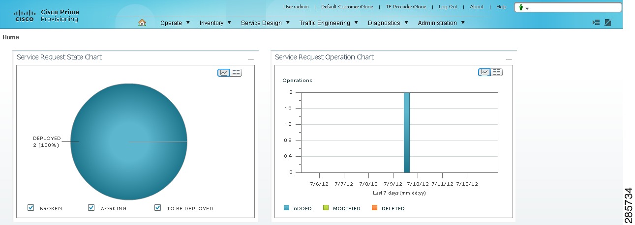
After you log into Prime Provisioning, the first window to appear is the Home window, as shown in Figure 1-1, "Home Window."
Figure 1-1 Home Window
Note
There are two new charts available in the home screen, which provides a count of SR's in different states and list the SR's deployed for the past seven days:
•
•
This overview includes the following sections:
Links
In the upper right-hand corner of the Home window (Figure 1-1), additional links appear that function as follows:
•
•
User
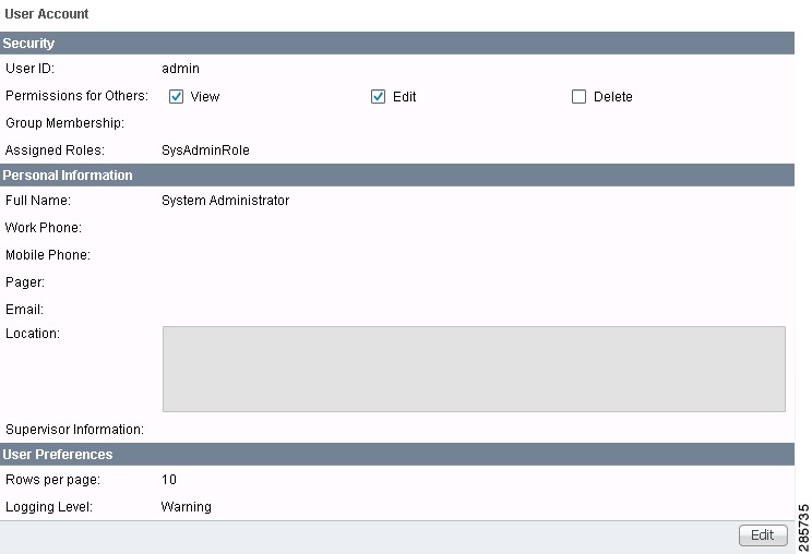
The User in the Home page is User: followed by admin (default) or a username. When you click User: admin the following window appears:
Figure 1-2 User: admin window
You can change your password without the SysAdmin or UserAdmin privileges when you click the Edit button. This allows you to edit the user profile, including changing the password.
Customer
The Customer in the Home page is Customer: followed by None (default) or a customer name. This is referred to as Customer Context. The advantage of Customer Context is to focus only on information for a specified customer. This link becomes active when a default customer is set. The default customer can edit or view customer context.
TE Provider
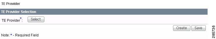
The TE Provider in the Home page is TE Provider: followed by None (default) or a TE provider name. This is referred to as TE Provider Context. The advantage of TE Provider Context is to focus only on information for a specified provider. To set the Provider Context, follow these steps:
Step 1
Figure 1-3 TE Provider Context
Step 2
Step 3
Figure 1-3, reappears with the name of the selected TE provider. Click Save or highlight the TE provider name and click Clear to reset the TE provider for which you want information.
The TE provider you chose now appears after TE Provider: on the Home window and it is the only TE Provider for which information appears.
Step 4
Logout
When you click Logout, you log out of the product.
About
When you click About, you receive the product name and version.
Help
When you click Help, you receive a pointer to the Prime Provisioning documentation:
http://www.cisco.com/en/US/products/ps12199/tsd_products_support_series_home.html
From that location, you can choose the type of Prime Provisioning document you want to see.
Common GUI Components
GUI components that are common on many windows are as follows:
Filters
As shown in Figure 1-4, you can filter information in the different windows of the software using the below instructions.
Figure 1-4 Example of Filtering, Header Row Check Box, Rows per Page, and Changing Pages
Note
Step 1
Step 2
a.
b.
Step 3
Step 4
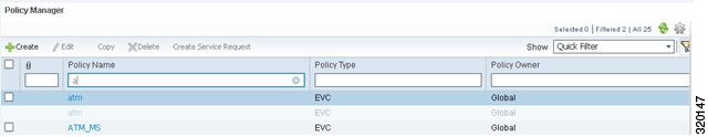
As shown in Figure 1-5, in some windows of the software such as Policy Manager, Customer and Toggle Picker of the Service Request Editor window, quick filtering option is present.
Figure 1-5 Example of Quick Filter
When you select Quick Filter from the Show drop-down list and start typing in any of the text fields, the list is automatically filtered. The count of the filtered records is shown in the top right corner. From the available records, if you want to keep certain rows visible as you scroll to others, you need to fix the rows.
To fix a row, do the following:
Step 1
Step 2
Step 3
Step 4
The selected row remains fixed at the top or bottom as selected while also appearing greyed out in the scroll list. You can detach a row by selecting it and choosing Detach Row from the Settings icon.
Header Row Check Box
Many windows have a check box in the header row, where the column names exist, as shown in Figure 1-4. If you check this check box, then all check boxes in the window are chosen.
Rows per Page
In the bottom left corner of many windows, as shown in Figure 1-4, you can change the number of rows shown on this window in Rows per page. Click the drop-down list and you can select 5, 10, 20, 30, 40, 50, 100, 500, 1000, or 2500.
Go To Page
Near the bottom in the right corner of many windows, as shown in Figure 1-4, there is Go to page field of y. In the field, you can enter the page you want to choose and then click the Go button to get there. The y indicates the last page for this topic. Another way to choose a specific page is to use the arrows. You can click the > arrow to choose the next page or the furthest arrow to the right >| to choose the last page. You can click the < arrow to choose the previous page or the furthest arrow to the left |< to choose the first page.
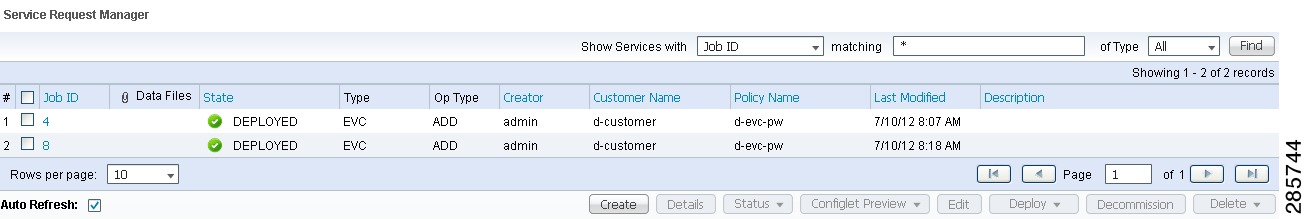
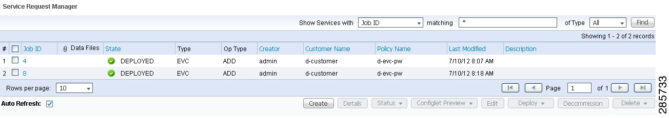
Auto Refresh
At the bottom left corner of several windows, there is a check box used to enable or disable the Auto Refresh feature, as shown in Figure 1-6. Checking this check box causes the window and its data to refresh every n milliseconds. The amount of time between refresh cycles can be set in the DCPL property: GUI.srRefreshRate. By default, the Auto Refresh feature is enabled to 30000 milliseconds.
Color Coding
In the Service Request table, the Task table, and the Device table, the colors you see indicate the state of the items, as shown in Figure 1-6.In the Service Request table, the states have the following colors:
•
•
•
•
•
•
•
•
•
•
•
•
In the Task table, the states have the following colors:
•
•
•
•
•
•
In the devices table, the states have the following colors:
•
•
•
Figure 1-6 Colors as Identifiers
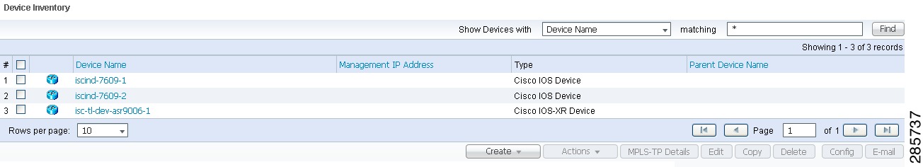
Icons
In some windows with tables of information, icons appear to show the type of device, as shown in Figure 1-7.
Note
Figure 1-7 Devices—Icons
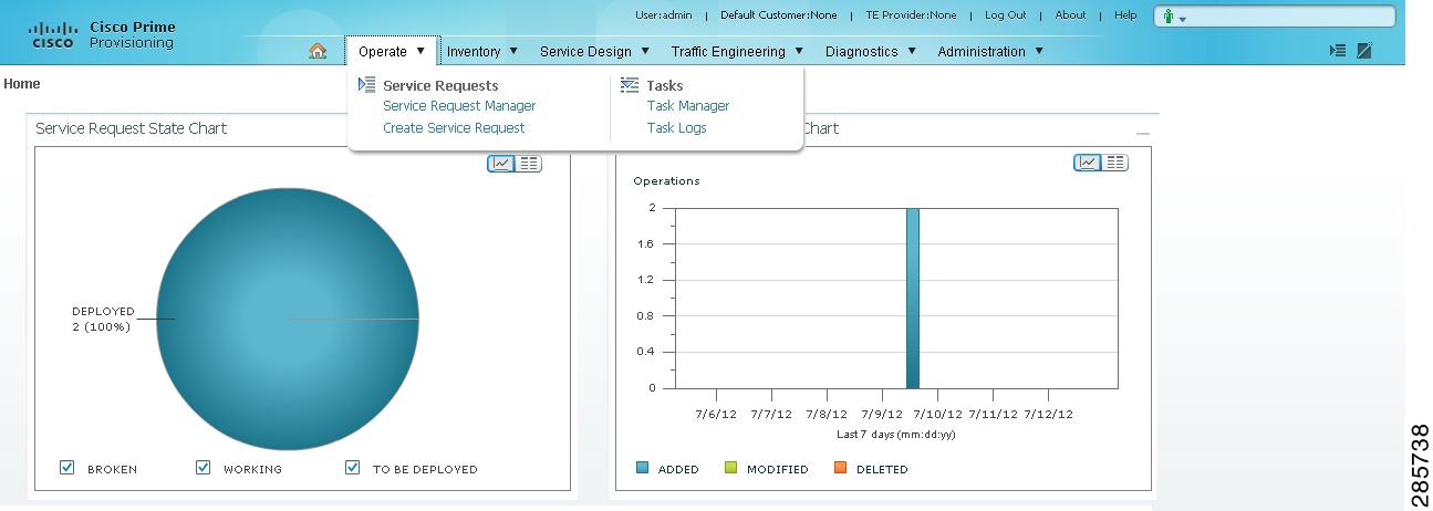
Operate
Operate contains tools to create and manage Service Requests and the various tasks of Prime Provisioning.
From the Home window you receive upon logging in, click the Operate tab and you receive a window as shown in Figure 1-8.
Figure 1-8 Operate Selections
The selections are as follows:
•
•
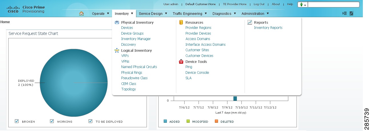
Inventory
Inventory contains tools to manage physical and logical inventory elements, resources, device tools, and reports.
From the Home window you receive upon logging in, click the Inventory tab and you receive a window as shown in Figure 1-9.
Figure 1-9 Inventory Selections
The selections are as follows:
•
–
–
–
•
•
•
–
•
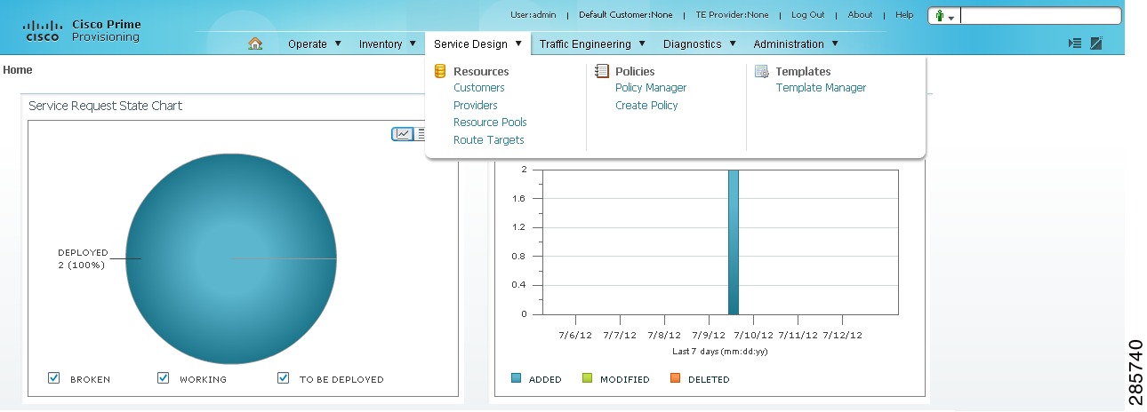
Service Design
Service Design contains management tools for creating and managing resources, policies, and templates.
From the Home window you receive upon logging in, click the Service Design tab and you receive a window as shown in Figure 1-10.
Figure 1-10 Service Design Selections
The selections are as follows:
•
–
–
–
–
•
•
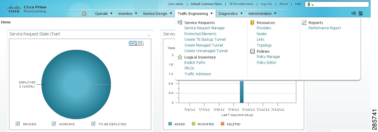
Traffic Engineering
Traffic Engineering contains tools to create, deploy, and manage elements of Traffic Engineering Management. This is explained in detail in Chapter 8 "Managing MPLS Traffic Engineering Services."
From the Home window you receive upon logging in, click the Traffic Engineering tab and you receive a window as shown in Figure 1-11.
Figure 1-11 Traffic Engineering Selections
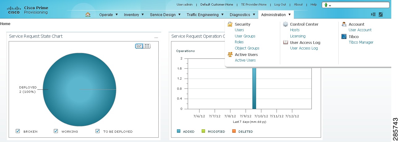
Administration
Administration contains tools to manage users, Prime Provisioning configuration, servers, and licensing, to view users and the user access log, and to specify attributes for some messages.
From the Home window you receive upon logging in, click the Administration tab and you receive a window as shown in Figure 1-12.
Figure 1-12 Administration Selections
The selections are as follows:
•
–
–
–
–
•
–
Note
–
–
•
•
•