Table Of Contents
Managing Gateways and Units
Displaying Gateway and Unit Information
Displaying Detailed Gateway and Unit Information and Performance
Managing Gateway and Unit Connectivity
Managing Device-to-Unit Assignments
Displaying Device-to-Unit Assignments
Creating Device-to-Unit Maps
Editing Device-to-Unit Maps
Deleting Device-to-Unit Maps
Changing a Device-to-Unit Assignment
Creating Unit Protection Groups
Unit Protection Group Failover Scenarios
Managing Gateway High Availability
Managing Local High Availability
Local HA Operations Notes
Local HA Failovers and Switchovers
Freezing and Unfreezing RHCS
Switching the RHCS Cluster Server
Changing the Floating IP Address
RHCS Log Messages
Configuring the RHCS Conga Web Interface
Managing Geographical High Availability
Displaying Geographical HA Status
Switch the Primary and Secondary Geographical HA Gateways
Configure Geographical HA
Synchronizing the Geographical HA Gateways
Freezing and Unfreezing Geographical HA Gateways
Backing Up and Restoring Geographical HA Gateway Data
Accessing Geographical HA Gateways Using the GUI
Managing Devices in Geographical HA Gateways
Managing Users in Geographical HA Gateways
Managing Reports, Views, and Groups in Geographical HA Gateways
Managing Alarms and Events in Geographical HA Gateways
Managing Thresholds in and Upstream Alarm Hosts in Geographical HA Gateways
Configuring SSL on Geographical HA Gateways and Remote Units
Unit Redundancy Groups and Geographical HA
Managing Geographical and Local High Availability
Manual Disaster Recovery
Managing Gateways and Units
Prime Performance Manager gateway and unit management includes:
•
Displaying gateway and unit information.
•
Managing device-to-unit assignments.
•
Creating and managing unit protection groups.
•
Creating and managing local and geographical gateway high availability.
The following topics describe gateway and unit management:
•
Displaying Gateway and Unit Information
•
Managing Device-to-Unit Assignments
•
Creating Unit Protection Groups
•
Unit Protection Group Failover Scenarios
•
Managing Gateway High Availability
Displaying Gateway and Unit Information
Prime Performance Manager allows you to view information about the gateways and units that are provisioned including details about the gateway and unit servers, alarms, events, and device-to-unit distributions. In addition, you can view more detailed server information including CPU, memory, and disk space utilization, user statistics, and other detailed information.
To display gateway and unit server statistics, from the Performance menu, choose Dashboards, then choose Server Health Dashboards. The following dashboards are displayed:
•
Server CPU/Memory/Disk—Displays CPU, memory, and disk and swap space utilization.
•
Server CPU/Memory/DiskIO—Displays CPU and memory utilization and disk read and write bytes.
•
Server CPU/Memory/Interface—Displays CPU, memory, and interface utilization, and interface error and discard percentages.
•
Server CPU/Memory/Temperature—Displays CPU and memory utilization and CPU temperatures.
•
Server Disk—Displays disk and swap space utilization and disk read and write bytes.
•
Server Processes/Users—Displays server process and user statistics.
Note
Gateway and unit statistics appear require the gateway and unit to added as a Prime Performance Manager device. For information, see Discovering Gateways and Units.
To display general gateway and unit information, from the System menu, choose Gateway/Units. The System Gateway/Units window displays the gateway and unit properties listed in Table 12-1.
Table 12-1 Gateway and Unit Properties
Column
|
Description
|
Internal ID1
|
Gateway or unit internal ID. Prime Performance Manager assigns the ID for its internal use.
|
Display Name
|
Gateway or unit or display name.
|
Custom Name
|
Gateway or unit or display name custom name, if created.
|
IP Address or DNS Hostname
|
Gateway or unit IP address or DNS name.
|
Primary SNMP Address
|
Gateway or unit SNMP IP address.
|
Redundancy Group1
|
If the unit belongs to a redundancy group, the redundancy group name. See Creating Unit Protection Groups.
|
Primary/Redundant1
|
If the unit belongs to a redundancy group, the unit role in the group, either Primary or Redundant.
|
Type
|
Description of the device type, either gateway or unit.
|
Connection Time
|
Connection time with the server to a unit or gateway.
|
In Service
|
Total time the gateway or unit is in service.
|
Last Status Change1
|
Date and time that the status of the gateway or unit last changed.
|
Status
|
Current status of the unit or gateway. Possible values are:
• Active
• Standby
• Discovering
• Polling
• Unknown
• Unmanaged
• Waiting
• Warning
|
Status Reason
|
Reason for the current status. For a full list of possible reasons, see the stateReasons.html file, located in the following directory:
/opt/CSCOppm-gw/apache/share/htdocs/eventHelp
If you cannot see all of the status reason, place the cursor over the cell to see the full text in a tooltip.
|
Out of Sync
|
If the gateway is installed in a geographical HA configuration, indicates whether the primary gateway database is out of sync to the secondary one.
|
To display detailed gateway or unit information, select the gateway or unit in the navigation area. Table 12-2 lists the information that is displayed.
Note
The Reports, Dashboards, and Report Status tabs require the gateway and unit to added as a Prime Performance Manager device. For information, see Discovering Gateways and Units.
Table 12-2 Detailed Gateway and Unit Properties
Tab
|
Description
|
Reports
|
Displays gateway or unit reports. These are the same reports you see when choosing Devices from the Network menu, selecting the gateway or unit from the device list and clicking the Reports tab. For more information, see Managing Reports, Dashboards, and Views.
|
Dashboards
|
Displays gateway or unit dashboards. These are the same dashboards you see when choosing Devices from the Network menu, selecting the gateway or unit from the device list and clicking the Dashboards tab. For more information, see Managing Reports, Dashboards, and Views.
|
Details
|
Provides detailed gateway or unit information. For a description of the detailed gateway and unit information, see Displaying Detailed Gateway and Unit Information and Performance
|
Event History
|
Displays the gateway or unit event history. For a description of the event properties, see Displaying Active Alarms and Event History.
|
Active Alarms
|
Displays the gateway or unit active alarms. For a description of the alarm properties, see Displaying Active Alarms and Event History.
|
Report Status
|
Displays the status of reports generated from the gateway or unit and allows you to enable or disable them. For more information, see Managing Reports, Dashboards, and Views.
|
Devices for Unit (Units only)
|
Displays the devices assigned to the selected unit. For a description of device properties, see Displaying Network-Level Device Properties.
|
Device Distributions for Unit (Units only)
|
Displays the device distributions for the selected unit. For a description of device properties, see Displaying Device Type Distributions.
|
Displaying Detailed Gateway and Unit Information and Performance
To display detailed Prime Performance Manager gateway and unit naming, status, and performance information:
Step 1
From the System menu, choose Gateways/Units.
Step 2
In the System Gateway/Units window, click the link of the gateway or unit whose detailed information and status you want to view.
Step 3
In the gateway or unit window, click Details.
The following gateway or unit information is displayed:
•
Naming Information
–
Display Name—The gateway or unit display name.
–
Custom Name—The gateway or unit custom name.
–
DNS Name—The gateway or unit DNS name.
–
IP Address—The gateway or unit IP address.
–
Type—The type, either gateway or unit.
–
In Service—Indicates whether the gateway or unit is in service.
–
Connection Time—Provides the gateway or unit connection time.
•
Status Information
–
Alarm Severity—The severity of the highest alarm on the gateway or unit.
–
Status—The gateway or unit status, either Active or Inactive.
–
Last Status Change—The date and time of the last status change.
–
Status Reason—The date and time of the last status change.
•
Server Hardware Performance
–
Average CPU Utilization (Last 15 Min)—CPU utilization within the last 15 minutes.
–
Average CPU Utilization (Last 60 Min)—CPU utilization within the last 60 minutes.
–
Avg Server Memory Utilization (Last 15 Min)—Server memory utilization within the last 15 minutes.
–
Avg Server Memory Utilization (Last 60 Min)—Server memory utilization within the last 60 minutes.
Note
Utilization data text color is based on the Utilization Color Settings defined in User Preferences. For information, see Changing User Preferences.
•
Gateway (or Unit) Performance
–
Max JVM Memory Utilization (Last 15 Min)—Maximum Java Virtual Machine (JVM) utilization within the last 15 minutes.
–
Max JVM Memory Utilization (Last 60 Min)—Maximum JVM memory utilization within the last 60 minutes.
–
Avg JVM Memory Utilization (Last 15 Min)—Average JVM memory utilization within the last 15 minutes.
–
Avg JVM Memory Utilization (Last 60 Min)—Average JVM memory utilization within the last 60 minutes.
Note
Utilization data text color is based on the Utilization Color Settings defined in User Preferences. For information, see Changing User Preferences.
–
Average Scheduler Queue Size—Average scheduler queue size. This indicates the number of polling requests that are waiting in queue. 0 indicates polling requests are being processed normally. An increasing number indicates a backlog exists that might result in polling delays. To investigate, check the number of active Go Live sessions and reports with 1-minute polling enabled. For additional information, see Displaying Network and Device Reports.
–
Persistence Directory Disk Usage—The usage data for the Prime Performance Manager directory where Prime Performance Manager data files are stored (/opt/CSCOppm-gw/data/ or /opt/CSCOppm-unit/data) MB or GB used and MB or GB available.
–
Log Directory Disk Usage—The usage data for the Prime Performance Manager log directory (/opt/CSCOppm-gw/logs/ or /opt/CSCOppm-unit/logs) MB or GB used and MB or GB available.
–
Report Directory Disk Usage—The usage data for the Prime Performance Manager reports directory (/opt/CSCOppm-gw/reports/ or /opt/CSCOppm-unit/reports) MB or GB used and MB or GB available.
–
Backup Directory Disk Usage—The usage data for the Prime Performance Manager backup directory (/opt/) MB or GB used and MB or GB available.
Managing Gateway and Unit Connectivity
Gateway to unit connectivity requires that the unit hostname be resolvable on the gateway. To ensure gateway-to-unit connectivity is lost due to an unresolved unit hostname, you can perform any of the following actions:
•
On the unit, use the unit IP address as its server name not its hostname:
/opt/CSCOppm-unit/bin/ppm servername = 1.2.3.4
•
On the gateway add an entry to the /etc/hosts file for the unit.
•
Add a DNS entry for the unit.
Managing Device-to-Unit Assignments
Prime Performance Manager allows you to create multiple units, assign them to a gateway and distribute the network devices among them. During device discovery, whether performed from Prime Performance Manager or by importing the Prime Network device inventory, Prime Performance Manager assigns devices to units based upon the device-to-unit mappings that you must create in the Unit Editor administrative tab. You can create these mappings before or after device discovery. If you create the mappings before device discovery, Prime Performance Manager assigns the devices to the units based on the information in the maps. If device-to-unit maps are not present when device discovery is run, Prime Performance Manager assigns all discovered devices to the unit installed with the gateway, if present, or to another unit if a collocated unit is not installed.

Note
Determining the best allocation of devices among multiple units will take time. Many factors are involved including the unit server size, the number of enabled reports, the number of reportable objects, and many other factors.
The following topics tell you how to create and manage the device-to-unit maps:
•
Displaying Device-to-Unit Assignments
•
Creating Device-to-Unit Maps
•
Editing Device-to-Unit Maps
•
Deleting Device-to-Unit Maps
•
Changing a Device-to-Unit Assignment
Displaying Device-to-Unit Assignments
If your Prime Performance Manager implementation has only one unit, all devices in your network are assigned to it. If you have allocated devices to multiple units, an easy way to view the device-to-unit assignments is to add the Unit parameter to the Devices table. To do this:
Step 1
From the Network menu, choose Devices.
Step 2
Right-click the table header and add the Unit parameter.
Step 3
Click Apply. (The Apply button is located at the bottom of the parameter list.)
For additional information, see:
•
Displaying Network-Level Device Information
•
Creating and Editing Device Polling Groups
Creating Device-to-Unit Maps
The following procedure tells you how to create a device-to-unit map to distribute devices across multiple units. Before you complete the procedure, you will need the IP addresses or address ranges of all discovered devices, and a plan on how you want to distribute them across the units.
To create the map:
Step 1
Log into the Prime Performance Manager GUI as a System Administrator user.
Step 2
From the Administration menu, choose Unit Editor.
Step 3
On the Unit Editor toolbar, click Add a Device to Unit Map.
Step 4
In the Add Device to Unit Map dialog box, enter the following:
•
IP Address Range or Hostname—Enter the device IP ad dress, device IP address range, or hostname of the device(s) you want to assign to the unit for this map.
•
Unit—Choose the unit where you want to assign the devices. The field is populated with units that are assigned to the gateway.
Step 5
Click OK.
The map is added to the Unit Editor table.
Step 6
Repeat Steps 3 through 5 until you have completed the device maps that you want.
Step 7
In the Unit Editor toolbar, click Save all Unit Entries.
Step 8
Choose one of the following:
•
If device discovery has been completed and you want to redistribute the devices now, on the Unit Editor toolbar, click Redistribute Devices to Units. Click OK on the confirmation dialog.
•
If device discovery is not completed, you can run it at any time. During device discovery, devices are assigned to units based on the maps in the Unit Editor table. For device discovery procedures, see Chapter 5 "Discovering Network Devices."
Editing Device-to-Unit Maps
To edit a device-to-unit map, complete the following steps:
Step 1
Log into the Prime Performance Manager GUI as a System Administrator user.
Step 2
From the Administration menu, choose Unit Editor.
Step 3
In the Unit Editor device-to-unit entries, edit the following:
•
IP Address Range or Hostname—In the table cell, you can edit the device IP address, device IP address range, or hostname.
•
Unit—If you want to assign the IP address or address range to a different unit, choose the unit from the drop-down list, which displays units connected to the gateway.
Step 4
When you are finished, in the Unit Editor toolbar, click Save all Unit Entries.
Step 5
Choose one of the following:
•
If device discovery is completed and you want to redistribute the devices based on the edits, on the Unit Editor toolbar, click Redistribute Devices to Units. Click OK on the confirmation dialog.
•
If device discovery is not completed, you can run it at any time, and the edited device-to-unit maps will be applied at that time.
Deleting Device-to-Unit Maps
To delete a device-to-unit map:
Step 1
Log into the Prime Performance Manager GUI as a System Administrator user.
Step 2
From the Administration menu, choose Unit Editor.
Step 3
In the Unit Editor device-to-unit entries, click the map table row(s) that you want to delete. To select more than one map, press Shift.
Step 4
When you are finished, in the Unit Editor toolbar, click Save all Unit Entries.
Step 5
Choose one of the following:
•
If device discovery is completed and you want to redistribute the devices based on the edits, on the Unit Editor toolbar, click Redistribute Devices to Units. Click OK on the confirmation dialog.
•
If device discovery is not completed, you can run it at any time, and the edited device-to-unit maps will be applied at that time.
Changing a Device-to-Unit Assignment
If your network has multiple Prime Performance Manager units, you can change the device unit assignment by editing the device-to-unit map. (See Editing Device-to-Unit Maps.) You can also change the device unit assignment by individual device in the Devices window.
To change a device assignment:
Step 1
Log into the Prime Performance Manager GUI as a System Administrator user.
Step 2
From the Network menu, choose Devices.
Step 3
In the device table, choose the device(s) whose unit assignment you want to change. To choose more than one device, press Shift.
Step 4
From the Actions menu, choose Relocate Device.
Note
This option is greyed if only one unit is available.
Step 5
In the Relocate Device dialog box, choose the unit to which you want to assign the device(s), then click Relocate.
The new device-to-unit assignments will occur immediately.
Creating Unit Protection Groups
Prime Performance Manager protection groups provide protection for units on a 1:1 or N:1 basis, where N = any number of primary units. Prime Performance Manager unit protection groups include the following key points:
•
Redundancy groups are created after Prime Performance Manager installation using the ppm redundancygroups command; they cannot be created or managed using the Prime Performance Manager GUI.
•
Multiple redundancy groups can be created. However a unit can only belong to one redundancy group.
•
A unit added to a protection group as a redundant unit cannot have devices attached to it. If a failure occurs to a primary unit, the devices attached to the primary unit are switched to the redundant unit.
•
Devices cannot be added to units in standby status, regardless of whether the unit is designated as a primary or standby unit. If a redundant unit become active due to a switchover, the following occurs:
–
When you request a new device discovery, the device is directed to the active redundant unit for processing. After the failback to the primary unit, the primary unit processes the discovered device(s).
–
When you move a device to the active redundant unit, the device is moved to the active redundant unit. After the failback, the primary unit processes the moved device.
–
If you move a device from an active redundant unit to another unit, the move is completed. After the failback, the primary unit does not process the moved node.
–
Moving a device to a failed primary unit is not allowed.
•
To prevent units from engaging in down/up flapping, a switchover delay is provided. The delay is the amount of time the gateway waits after a unit becomes unavailable before it initiates a failover to the redundant unit. You specify the length of the delay when you create the redundancy group. The gateway determines the unit unavailability based on a unit connection that is lost. The connection can be lost for many reasons, for example, the unit is shut down or it crashes, or the network connectivity between the gateway and unit is lost.
•
After the problem that caused a switchover is resolved, you must manually initiate the return to the primary unit using the ppm redundancygroups failback command.
•
Following a switchover, redundant units service devices in the same manner as the primary unit. State changes are communicated to the gateway. After a failback, the primary unit picks up where the redundant unit left off.
To create a unit redundancy group, use the ppm redundancy command:
ppm redundancygroups [list | detail | create | add | remove | delete | redundant | delay | enable | disable | failover | failback | import | export]
•
list—Lists the redundancy groups defined on the gateway, similar to the following:
ppm redundancygroups list
groupA, Enabled, Number of Units: 2
groupB, Enabled, Number of Units: 4
•
detail [group name]—Lists the redundancy group details, similar to the following:
ppm redundancygroups detail groupA
Created: Wed Sep 21 11:44:36 EDT 2011
Last Modified: Wed Sep 21 11:44:36 EDT 2011
Last Modified User: localhost
•
create [group name | delay | unit(s)...]—Creates a redundancy group with the provided group name, switchover delay (in seconds), and unit(s).
•
add [group name | unit(s) ...]—Adds unit(s) to a redundancy group.
•
remove [group name | unit(s) ...]—Removes a unit(s) from a redundancy group.
Note
A redundant unit cannot be removed from a redundancy group. To remove a redundant unit, you must change the redundant unit for the group, then you can remove the old redundant unit. Another option is to delete and recreate the redundancy group.
•
delete [group name]—Deletes a redundancy group. The unit redundancy mode is not checked.
•
redundant [group name | unit]—Changes the redundant unit of a redundancy group. No devices can be attached to the new redundant node.
•
delay [group name | delay]—Changes the redundancy group failover delay. The delay is the number of seconds the gateway waits after detecting a unit unavailability before it initiates a failover to the redundant unit.
•
enable [group name]—Enables a redundancy group.
•
disable [group name]—Disables a redundancy group. If a group is disabled, automatic failovers do not occur. However, you can perform manual failovers and failbacks.
•
failover [unit]—Forces the failover of a unit to the redundant unit.
•
failback [unit]—Initiates a return of control from the redundant unit to the specified unit.
•
import [/directory/filename]—Imports redundancy group definitions from the provided file name.
•
export [/directory/filename]—Exports redundancy group definitions to the provided file name.
Note
Unit protection groups cannot be created or managed using the Prime Performance Manager GUI.
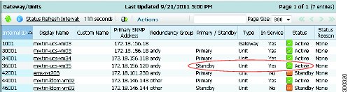
After protection groups are created, you can view them in the Gateway/Units summary list, as shown in Figure 12-1. The Redundancy Group column shows whether the unit belongs to a redundancy group, and if so, the name of the group to which the unit is assigned. The Primary/Redundant column shows the role of the unit in the redundancy group, either primary or redundant, The Status column indicates the unit status, either active or standby.
Figure 12-1 Protection Groups
1
|
Redundancy Group column.
|
3
|
Status column.
|
2
|
Primary/Redundant column.
|
|
|
Figure 12-2 shows a redundant unit that has been switched to active status.
Figure 12-2 Redundant Units in Active Status
Unit Protection Group Failover Scenarios
Table 12-3 describes the unit protection group and failover behavior after common network circumstances occur.
Table 12-3 Unit Protection Group Failover Scenarios
Circumstance
|
Response
|
Unit is shut down or fails.
|
The gateway waits for the delay time configured for the protection group. After the gateway determines the unit is down, it forces a failover of its devices to the redundant unit. The redundant unit begins collecting statistics for the devices; it now owns the devices and forwards CSV data to the gateway. The gateway accesses the redundant server for interactive reports. The unit that is down does not collect statistics. After it recovers and reconnects to the server, a handshake occurs and the gateway informs the unit that it is being covered for by a redundant unit. The failed unit is placed in a standby state and remains idle. It does not poll any devices; however, it can provide historical data to the gateway for interactive reporting.
To return the failed unit to its primary role, you must issue a failback. After the failback is requested, the devices on the redundant unit return to the primary unit and processing continues on the primary unit. The redundant unit returns to standby state and stops device polling, although it can participate in interactive reports. The primary unit returns to normal state and begins forwarding CSV data to the gateway.
|
Connectivity between a gateway and unit is lost.
|
The redundant unit picks up for the "failed" unit and takes ownership of its devices. During the network connectivity unavailability, the redundant unit and the primary unit both poll the devices. The primary unit does not forward data to the gateway, because it cannot connect to the gateway. After connectivity is restored and the unit reconnects to the gateway, during the handshake the unit recognizes that a redundant unit is processing for it, so it drops any data queued for the gateway. This includes CSV and event data. The "failed" unit is placed in a standby state and is idle. It does not poll any devices; however it can provide historical data to the gateway for interactive reporting. To return the primary unit to its original role, you must issue a failback command.
|
The gateway is brought down or fails.
|
The unit continues to process devices and queue data for the gateway. After the gateway is restored, the unit forwards the queued data to it. Because the gateway contains the unit protection group configuration information, a gateway failure causes the unit redundancy to be lost. If a gateway is down and a unit that is part of a redundancy group fails, the redundant unit will not take over for the failed unit.
|
Managing Gateway High Availability
Prime Performance Manager provides both local and geographical high availability. HA installations include:
•
Local HA only
•
Geographical HA only
•
Local and geographical HA
Prime Performance Manager HA management procedures are provided in the following topics:
•
Managing Local High Availability
•
Managing Geographical High Availability
•
Managing Geographical and Local High Availability
Managing Local High Availability
For local HA, Prime Performance Manager uses the Red Hat Cluster Suite (RHCS) provided with the Red Hat Enterprise Linux 5.5 (RHEL 5.5), Red Hat Enterprise Linux 5.7 (RHEL 5.7), Red Hat Enterprise Linux 5.8 (RHEL 5.8) Advanced Program.
The RHCS cluster infrastructure provides the basic functions that allow the Prime Performance Manager gateways to work together as a cluster. RHCS components include:
•
Cluster infrastructure—Provides fundamental functions for nodes to work together as a cluster: configuration-file management, membership management, lock management, and fencing.
•
High Availability Service Management—Provides failover of services from one cluster node to another when a node becomes inoperative.
•
Cluster administration tools—Provides configuration and management tools for setting up, configuring, and managing a Red Hat cluster including the cluster infrastructure components, the high availability and service management components, and storage.
Note
Before performing any RHCS configuration changes, following the guidelines provided in Gateway HA Operations Notes.
The Prime Performance Manager local HA utilizes a fencing hardware unit to cut off a gateway server from the shared storage. Fencing ensures data integrity and prevents a split brain scenario, where the gateway servers are disconnected from each other and each assumes the other has failed. If a failure occurs, the cut off can be accomplished by powering off the node with a remote power switch, disabling a switch channel, or revoking a host's SCSI 3 reservations. Figure 12-3 shows the local HA architecture.
Figure 12-3 Local High Availability Architecture
Note
Because of RHCS limitations, IPv6 is not supported on gateways configured for local HA.
Additional RHCS information can be found at the Red Hat website: http://www.redhat.com/.
Local HA Operations Notes
Before you perform any Prime Performance Manager local HA operation, review the following notes:
•
To avoid data loss, never manually mount or unmount a gateway storage device while Prime Performance Manager local HA is running. Always stop the Prime Performance Manager local HA service first.
•
Always mount a storage device to one HA gateway server; never mount the storage device to both local HA gateway servers.
•
Never access the storage device directories while RHCS configuration is in progress. If RHCS configuration starts and a user accesses a storage mount directory, a mount/unmount failure will occur.
•
If the local HA service is running and you want to stop, restart, or upgrade, Prime Performance Manager, or perform any similar action affecting Prime Performance Manager operability, you must:
1.
Freeze the RHCS HA service following the "Freezing and Unfreezing RHCS" procedure.
2.
Complete the Prime Performance Manager operation.
3.
Unfreeze the RHCS service following the "Freezing and Unfreezing RHCS" procedure.
If you do not freeze RHCS, RHCS will detect the Prime Performance Manager action as a failure and begin the recovery process. This can include restarting and relocating Prime Performance Manager, or disabling the service, which will cause Prime Performance Manager stop working temporally.
Local HA Failovers and Switchovers
After the Prime Performance Manager gateway local HA cluster is deployed, failovers are automatic. If a single service failure occurs, RHCS attempts to restart the service. If the restart fails, the service is relocated and started on the second gateway server.
Human intervention is required only in exceptional cases, such as database corruption or a component failure, and the component is not configured for HA. Manual switchovers are performed using the RHCS web GUI or the CLI clusvcadm utility. After a failed node is repaired, you must perform a manual switchover to revert the cluster to its original configuration.
Note
For complete redundancy, a configuration with no single point of failure is recommended. See the RHCS documentation for recommended configurations.
Two general conditions can trigger Prime Performance Manager local HA failovers:
•
The Linux server containing the RHCS that manages the local HA is not functioning properly, for example, network connectivity is down. If this occurs, the RHCS service is automatically relocated to the another RHCS server.
•
The Prime Performance Manager gateway is not functioning properly, for example, it cannot access the database. If this occurs, RHCS initiates recovery based upon the user-configured recovery policy:
–
Restart (recommended)—RHCS restarts the gateway on the server where it is installed. If the restart does not succeed, RHCS initiates the Relocate policy.
–
Relocate—RHCS switches to the backup gateway server immediately.
–
Disable—Do nothing; RHCS places the gateway service in disabled state.
During failovers, the gateway does not respond to its attached units, so units cache their requests. After the gateway service is back up, either by restarting the primary gateway successfully or by switching to the secondary gateway, the unit resends cached requests, so no data is lost.
To change the recovery policy after RHCS configuration, use the Red Hat Conga application following procedures in the RHCS documentation. Conga runs on a standalone RHCS server; it is not part of the Prime Performance Manager local HA cluster.
Freezing and Unfreezing RHCS
If you must stop Prime Performance Manager for any reason, you must freeze RHCS so that it stops checking the Prime Performance Manager status. Freezing RHCS places it in maintenance mode. If you stop Prime Performance without freezing RHCS, the cluster will detect that the services are down and attempt to restart it.
To freeze or unfreeze the RHCS cluster service:
Step 1
Log into the primary local HA gateway as a root user.
Step 2
Change to the HA lib bin directory, for example:
/var/CSCOppm-ha/ppm-ha-bin
Step 3
To freeze the RHCS service, enter the following command:
Step 4
To unfreeze the RHCS service, enter the following command:
./ppmGatewayHA.sh unfreeze
After unfreeze the service, the RHCS will back to the normal, and begin to check the ppm status periodically.
Switching the RHCS Cluster Server
On occasion, you might need to switch over the RHCS cluster server. To switch the server:
Step 1
Log into the primary local HA gateway as a root user.
Step 2
Change to the HA lib bin directory, for example:
/var/CSCOppm-ha/ppm-ha-bin
Step 3
Enter the following command:
./ppmGatewayHA.sh switchover
The RHCS service switches from the active to the standby gateway.
Note
All mount devices should only be accessed by Prime Performance Manager and not by other applications. For example, if you have another terminal accessing the mount device directories, use cd command to leave that directory.
Note
Do not perform a manual mount when the RHCS local HA service is running.
Changing the Floating IP Address
Use the following steps if, for any reason, you need to change the floating IP address for the primary and secondary local HA servers:
Step 1
Freeze RHCS following the "Freezing and Unfreezing RHCS" procedure.
Step 2
Stop the Prime Performance Manager gateway:
Step 3
Change the RHCS cluster service floating IP address using the Red Hat Conga GUI. (Conga runs on a standalone node and is not part of the cluster.)
Step 4
Verify that the new floating IP and its hostname mapping relationship are added in both the primary and the secondary gateways.
Step 5
On Prime Performance Manager gateway, enter the following command to change the gateway to the new floating IP address:
ppm servername servername
Step 6
On Prime Performance Manager unit, enter the following command to change the unit to the new floating IP address:
ppm gatewayname servername
Step 7
Start Prime Performance Manager gateway and unit and make sure Prime Performance Manager gateway and unit status is OK.
Step 8
Use Conga or CLI to unfreeze the cluster service for Prime Performance Manager.
RHCS Log Messages
The RHCS log messages provide information about cluster-related issues, such as service failure. Every thirty seconds, RHCS issues status commands to check the Prime Performance Manager, internal database, and other processors. These messages are logged to /var/log/messages and can be viewed by the root user, or from the RHCS web GUI. Sample RHCS log messages are provided below:
Jun 4 07:54:49 crdc-ucs-109 clurgmgrd[7629]: <notice> Starting stopped service
service:PPM_GW_HA
Jun 4 07:54:49 crdc-ucs-109 clurgmgrd: [7629]: <info> mounting /dev/sde1 on /ha
Jun 4 07:54:49 crdc-ucs-109 kernel: kjournald starting. Commit interval 5 seconds
Jun 4 07:54:49 crdc-ucs-109 kernel: EXT3FS on sde1, internal journal
Jun 4 07:54:49 crdc-ucs-109 kernel: EXT3-fs: mounted filesystem with ordered data mode.
Jun 4 07:54:49 crdc-ucs-109 clurgmgrd: [7629]: <info>quotaopts =
Jun 4 07:54:49 crdc-ucs-109 clurgmgrd: [7629]: <info> mounting /dev/sdf1 on /ha_array1
Jun 4 07:54:49 crdc-ucs-109 kernel: kjournald starting. Commit interval 5 seconds
Jun 4 07:54:49 crdc-ucs-109 kernel: EXT3FS on sdf1, internal journal
Jun 4 07:54:49 crdc-ucs-109 kernel: EXT3-fs: mounted filesystem with ordered data mode.
Jun 4 07:54:49 crdc-ucs-109 clurgmgrd: [7629]: <info>quotaopts =
Jun 4 07:54:49 crdc-ucs-109 clurgmgrd: [7629]: <info> mounting /dev/sdg1 on /ha_array2
Jun 4 07:54:49 crdc-ucs-109 kernel: kjournald starting. Commit interval 5 seconds
Jun 4 07:54:49 crdc-ucs-109 kernel: EXT3FS on sdg1, internal journal
Jun 4 07:54:49 crdc-ucs-109 kernel: EXT3-fs: mounted filesystem with ordered data mode.
Jun 4 07:54:49 crdc-ucs-109 clurgmgrd: [7629]: <info>quotaopts =
Jun 4 07:54:49 crdc-ucs-109 clurgmgrd: [7629]: <info> Adding IPv4 address
10.74.125.114/25 to eth0
Jun 4 07:54:51 crdc-ucs-109 avahi-daemon[7490]: Registering new address record for
10.74.125.114 on eth0.
Jun 4 07:54:52 crdc-ucs-109 clurgmgrd: [7629]: <info> Executing
/ha/CSCOppm-gw/bin/ppmGatewayHealth.sh start
Jun 4 07:54:52 crdc-ucs-109 logger: start /ha/CSCOppm-gw/bin/sgmServer.sh ....
Jun 4 07:54:52 crdc-ucs-109 logger: ppm is not running.
Jun 4 07:54:52 crdc-ucs-109 logger: call /ha/CSCOppm-gw/bin/sgmServer.sh start silent 3.
Jun 4 07:55:25 crdc-ucs-109 logger: ppm health: everything is OK, return 0
Jun 4 07:55:25 crdc-ucs-109 logger: ppm start OK!!!.
Jun 4 07:55:25 crdc-ucs-109 clurgmgrd[7629]: <notice> Service service:PPM_GW_HA started
Jun 4 07:56:02 crdc-ucs-109 clurgmgrd: [7629]: <info> Executing
/ha/CSCOppm-gw/bin/ppmGatewayHealth.sh status
Jun 4 07:56:06 crdc-ucs-109 logger: ppm health: everything is OK, return 0
Configuring the RHCS Conga Web Interface
The RHCS web interface is configured during installation. Use the information provided in this section only if you decide to change the web interface configuration after installation or if the web interface was not configured during installation.
Installing the RHCS web interface module on a standalone server instead of the dual primary or secondary gateway servers is recommended.
The RHCS luci web interface allows you to configure and manage storage and cluster behavior on remote systems. You will use it to manage the Cisco Prime Performance local HA. Before you begin this procedure, you should have the Red Hat Conga User Manual. It can be obtained at:
http://sources.redhat.com/cluster/conga/doc/user_manual.html
If your fencing device is supported by RHCS but not ipmilan type, that is, you chose the Manual fencing option during the installation; manually configure the device using the Red Hat fencing configuration documentation. This can be obtained at;
http://docs.redhat.com/docs/en-US/Red_Hat_Enterprise_Linux/5/pdf/Configuration_Example_-_Fence_Devices/Red_Hat_Enterprise_Linux-5-Configuration_Example_-_Fence_Devices-en-US.pdf
Note
The following procedure provides the general steps to configure the luci interface. See the Red Hat Conga User Manual for details on performing steps in this procedure.
Note
The RHCS web interface must be configured for both servers in the local redundant dual-node cluster.
Step 1
As root user, run the following command and enter the needed details:
Step 2
Edit /etc/sysconfig/luci to change the default port to an available port. (The default 8084 port is used by Prime Performance Manager.) For example:
# web UI fronted for remote cluster and storage management
Step 3
As root the root user, enter:
Step 4
Enter the web interface using the following link:
https://<node hostname>:<port>
Step 5
In the luci web interface, add the cluster that was configured by the Prime Performance Manager installation. See the Red Hat Conga User Manual for details on performing the following:
•
Add a system.
•
Add an existing cluster.
•
Add a user.
Step 6
If your fencing device is supported by RHCS but not by Prime Performance Manager, use the Red Hat fencing configuration guide to configure the device.
Note
If you provision a new fencing device, provision it as the primary fencing method. Keep the manual fencing agent as the backup fencing method.
Step 7
To use the web interface, connect to:
https://<cluster node hostname>:<port>
From the RHCS web interface you can stop, start, and relocate the services managed by the cluster.
Managing Geographical High Availability
The Prime Performance Manager geographical HA is installed in two different geographical locations, each configured with unique IP addresses. The two gateways work active-active on each site at the same time. The secondary gateway can take over immediately without administrative intervention if the primary site is not available.
This solution supports two kinds of deployment:
•
Both sides are installed on single gateway.
•
The primary gateway is deployed as a dual-end by the local HA and the secondary gateway is single.
Note
Do not install units within the primary or secondary geographical HA gateways.
The Prime Performance Manager geographical redundancy gateway HA is based on database and file synchronization:
•
Database synchronization—All database changes are synchronized from the primary to the secondary gateway. If the secondary gateway is not available when database changes occur, the primary gateway caches the changes. After secondary is up, the full synchronization will run the database synchronization first.
•
File synchronization—If changes occur to dynamic and static files, they are synchronized to the secondary gateway.
Geographical HA management procedures are provided in the following topics:
•
Displaying Geographical HA Status
•
Switch the Primary and Secondary Geographical HA Gateways
•
Configure Geographical HA
•
Synchronizing the Geographical HA Gateways
•
Freezing and Unfreezing Geographical HA Gateways
•
Backing Up and Restoring Geographical HA Gateway Data
•
Accessing Geographical HA Gateways Using the GUI
•
Managing Devices in Geographical HA Gateways
•
Managing Users in Geographical HA Gateways
•
Managing Reports, Views, and Groups in Geographical HA Gateways
•
Managing Alarms and Events in Geographical HA Gateways
•
Managing Thresholds in and Upstream Alarm Hosts in Geographical HA Gateways
•
Configuring SSL on Geographical HA Gateways and Remote Units
•
Unit Redundancy Groups and Geographical HA
Displaying Geographical HA Status
To display the geographical HA status:
Step 1
Log into the primary geographical HA gateway as a root user.
Step 2
Enter the following command:
/opt/CSCOppm-gw/bin/ppm primeha status
Prime Performance Manager provides static configuration and running status information for the primary and secondary gateway. Table 12-4 shows the primary gateway running status.
Table 12-4 Primary Gateway Running Status
Item
|
Description
|
Service Role
|
Indicates the HA role, in this case, Primary.
|
Freezed
|
If True, the gateway is frozen.
|
Message Queue
|
Displays all sync messages that primary gateway need to handle.
|
DB Stored Messages
|
The cached messages for database changes.
|
Messages count to
|
Current count of received messages that have not been handled.
|
Messages need ack
|
Count of messages sent to the secondary gateway for which acknowledgement is not received.
Note If this is not zero, do not switch over.
|
CSV files need sync
|
CSV files to be synced when it is enabled
Note If this is none zero, do not switch over
|
Out Of Sync: false
|
Up to DB cache limit or age out.
Note If true, run the ppm primeha backupdb to remove the label.
|
Table 12-5 shows the secondary gateway running status.
Table 12-5 Secondary Gateway Running Status
Item
|
Description
|
Service Role
|
Indicates the HA role, in this case, Secondary
|
Freezed
|
If True, the gateway is frozen.
|
Last Down Time
|
The time that primary gateway is detected down.
|
Primary Accumulate Down Times
|
If this value reaches the configured value, the service role manager takes over.
|
Acks to send back
|
Messages received from primary gateway that need acknowledgement.
|
Primary Gateway Alive
|
True means that current primary gateway is alive.
|
Initial Full Sync Done
|
When the secondary gateway connect to the primary gateway, database and files synchronizations occur.
Note If the initial full sync is not complete, do not restart server or run switch in primary gateway side.
|
Health Check Working
|
Indicates whether the health check is working. The primary side ppm primeha freeze/unfreeze will stop/start health check of secondary gateway.
|
Switch the Primary and Secondary Geographical HA Gateways
On occasion, you might need to manually switch the primary and secondary geographical HA gateways, for example, to perform server maintenance or upgrades, or for other reasons. To manually switch geographical HA gateways:
Step 1
Log into the primary geographical HA gateway as a root user.
Step 2
Complete the "Displaying Geographical HA Status" procedure to verify the gateway status. The following statuses are required:
•
Both primary and secondary gateways are active.
•
The following status indicators have "0" counts:
–
Message Queue
–
DB Stored Messages
–
Messages count to
–
Messages need ack
–
CSV files need sync
•
Connectivity exists between the primary and secondary gateway.
•
All the units connect to the current primary gateway.
Step 3
Enter the following command:
/opt/CSCOppm-gw/bin/ppm primeha switch
After the switchover, the following occurs:
•
Prime Network cross-launch capability, if installed on the primary gateway, is uninstalled and installed in the new one. For information about Prime Network cross launching, see Enabling Prime Network Cross-Launching.
•
No BQL update messages are sent to the old primary gateway.
•
Users can edit the server from web access.
•
Users can view the reports data.
•
Users can view the Views results.
•
The old primary gateway is view only.
•
Switch over events are raised for the new primary gateway.
Configure Geographical HA
You can configure a parameters that affect geographical HA processes. To configure geographical HA:
Step 1
Log into the primary geographical HA gateway as a root user.
Step 2
Enter the following command and configuration option:
/opt/CSCOppm-gw/bin/ppm primeha (peergatewayname | peergatewayrmiport |
healthcheckinterval | maxfailnum | synccsv |)
Command options include:
•
peergatewayname—Configures the IP address or hostname of peer gateway. If you are logged into the primary gateway, this would be the secondary gateway IP address or hostname. If you are logged into the secondary gateway, this would be the primary gateway IP address or hostname.
•
peergatewayrmiport—Configures the RMI port of peer gateway. The RMI port is the port used for HA communications If you are logged into the primary gateway, this would be the secondary gateway RMI port.
•
healthcheckinterval—Configures the frequency at which the primary and secondary gateways check their health status, in seconds.
•
maxfailnum—Configures the maximum number of continuous tolerated connectivity failures before a failover is initiated.
•
synccsv—Manually synchronizes the primary and secondary CSV files.
•
ageout—Configures the primary database age out, in hours.
•
cachelimit—The database differences cache records limitation.
Synchronizing the Geographical HA Gateways
If the primary and secondary gateways are out of synchronization, as indicated by the primary gateway Out of Sync parameter (see Displaying Geographical HA Status), complete the following steps to synchronize them:
Step 1
Log into the primary geographical HA gateway as a root user.
Step 2
Enter the following command:
ppm primeha backupdb {path}
Step 3
Remote copy the backup files to the secondary gateway.
Step 4
log into the secondary gateway and restore its database from the backed up primary database:
ppm start restoredb {dbpath}
Step 5
Restart the secondary gateway:
Freezing and Unfreezing Geographical HA Gateways
If you must stop the primary Prime Performance Manager gateway for any reason, you must freeze the geographical HA gateways to stop the primary and secondary gateway health checking. To freeze the geographical HA gateway;
Step 1
Log into the primary geographical HA gateway as a root user.
Step 2
Verify the secondary gateway is running. If not, you do not need to complete this procedure.
Step 3
Enter the following command:
/opt/CSCOppm-gw/bin/ppm primeha freeze
Health checking will stop on the secondary gateway.
Step 4
After you restart the primary gateway, unfreeze it to restart the secondary gateway health checking:
/opt/CSCOppm-gw/bin/ppm primeha unfreeze
Backing Up and Restoring Geographical HA Gateway Data
If the geographical gateways get out of synchronization, you will need to back up the primary gateway, copy the files to the secondary gateway and restore the data to it.
To back up and restore geographical HA data:
Step 1
Log into the primary geographical HA gateway as a root user.
Step 2
Enter the following command to backup the gateway data:
/opt/CSCOppm-gw/bin/ppm primeha backup
Step 3
Enter the following command to restore the gateway data:
/opt/CSCOppm-gw/bin/ppm primeha restore {filename}
The gateway system files are restored with specified backup file.
Accessing Geographical HA Gateways Using the GUI
You can view the primary and secondary gateways by choosing Gateways/Units from the System menu. Two gateways are displayed. One has an Active status and one has a Standby status. Any gateway edits can only be applied to the primary (Active) gateway. Changes to the user preference are automatically synchronized to secondary gateway.
Managing Devices in Geographical HA Gateways
Devices can only be imported from Prime Network into the primary HA gateway. Additionally, device discovery can only be run from the primary HA gateway. Device credentials added to the primary gateway are synchronized to secondary gateway. If a switchover or failover occurs, the new primary gateway automatically imports the primary gateway devices.
If Prime Network cross launch capability is implemented, Prime Network cross launches go to the primary HA gateway. After a switchover or failover, the new primary gateway reinstall the cross launch capability.
Any changes to devices credentials are synchronized from the primary to secondary gateway. Device discovery seed files are also synchronized from the primary to secondary gateway.
For information about device discovery, see Chapter 5 "Discovering Network Devices."
Note
You cannot update device information in the secondary HA gateway.
Managing Users in Geographical HA Gateways
In a geographical HA environment, users are handled in the following manner:
•
Primary gateway—User information is automatically synchronized from the primary to the secondary gateway when the secondary gateway starts and connects to the primary gateway.
•
Secondary gateway—For the secondary gateway, choose the same use authentication type that is used on the primary gateway and agree to use the existing user database when enabling user access.
For more information, see Chapter 6 "Managing Users and Security."
Managing Reports, Views, and Groups in Geographical HA Gateways
Changes to report settings in the primary gateway are synchronized to the secondary gateway. Report settings cannot be modified in the secondary gateway. Similarly, changes to the primary gateway views are synchronized to the secondary gateway. View modifications can only be performed on the primary gateway. The same principles apply to groups. Group settings cannot be changed on the secondary gateway. However, changes to the primary gateway groups are synchronized to the secondary gateway
Managing Alarms and Events in Geographical HA Gateways
The two HA gateways will display the same alarms and events. Any change to the event, such addition of notes, is synchronized to the secondary gateway. During switchover and failovers, the following events appear:
•
Gateway $FailedGateway switched over to $SecondaryGateway.
•
Gateway $FailedGateway failed over to $SecondaryGateway.
If two primary gateways detected, there will also one alarm issued.
If Prime Performance Manager discovers dual primary gateways, the following event is displayed: $LocalPrimaryGateway, $PeerPrimaryGateway.
Managing Thresholds in and Upstream Alarm Hosts in Geographical HA Gateways
Thresholds created on the primary gateway (see "Configuring Thresholds") are synchronized to the secondary gateway. Thresholds cannot changed on the secondary gateway. However, thresholds will operate after a switchover or failover to the secondary gateway. Threshold alarms raised on the primary gateway can be viewed on the secondary gateway.
If the OSS is enabled on the primary gateway (see Configuring Upstream Alarm Hosts and Tuning Event and Alarm Parameters), you can view the configuration results on the secondary gateway. The secondary gateway does not send any traps to its northbound interface unless a switchover or failover occurs.
Configuring SSL on Geographical HA Gateways and Remote Units
The following procedures cover the enabling of SSL on geographical HA gateways and remote units. For additional information, see Enable SSL on a Gateway or Collocated Gateway and Unit.
To enable SSL on the primary gateway:
Step 1
Log into the primary gateway as the root user.
Step 2
If the secondary gateway is up, complete the "Freezing and Unfreezing Geographical HA Gateways" procedure to freeze the primary gateway and stop the secondary gateway health checking.
Step 3
Enable SSL:
/opt/CSCOppm-gw/bin/ppm sslenable
Step 4
Enter y if you want to restart the gateway now, or n if you want to restart it later.
Step 5
If you froze the primary gateway in Step 2, complete the "Freezing and Unfreezing Geographical HA Gateways" procedure to unfreeze it.
To enable SSL on the secondary gateway:
Step 1
Log into the secondary gateway as the root user.
Step 2
Enable SSL on the secondary gateway.
Step 3
Import the secondary certificate into the primary gateway:
Step 4
Import the secondary certificate to all remote units.
Step 5
Import the primary gateway certificate to the secondary gateway.
Step 6
Import all the unit certificates to the secondary gateway.
Step 7
If secondary gateway is still up, complete the "Freezing and Unfreezing Geographical HA Gateways" procedure to freeze the primary gateway.
Step 8
Restart primary gateway.
Step 9
Restart secondary gateway.
Step 10
Restart all units.
Step 11
Run the ppm primeha status command in the primary gateway to see if it is frozen. If yes, complete the "Freezing and Unfreezing Geographical HA Gateways" procedure to unfreeze the primary gateway.
Enable SSL on remote units:
Step 1
Log into the remote unit.
Step 2
Enable SSL on the unit.
Step 3
Import the unit certificate to the primary gateway
Step 4
Import the unit certificate to the secondary gateway.
Step 5
Import the primary gateway certificate to the unit.
Step 6
Import the secondary gateway certificate to the unit.
Step 7
If secondary gateway is still up. complete the "Freezing and Unfreezing Geographical HA Gateways" procedure to freeze the primary gateway.
Step 8
Restart the primary gateway.
Step 9
Restart the secondary gateway.
Step 10
Restart the remote unit.
Unit Redundancy Groups and Geographical HA
Any changes to the unit redundancy groups, for example create, add, or delete, are synchronized to the secondary gateway. If a failover occurs in the unit redundancy group or the gateway HA, complete the following steps to stop the servers:
Step 1
Disable unit redundancy groups. See Creating Unit Protection Groups.
Step 2
Stop the protection unit. See Stopping Gateways and Units.
Step 3
Stop the work units.
Wait until all units are completely shut down.
Step 4
Stop the secondary gateway.
Step 5
Stop primary gateway.
Managing Geographical and Local High Availability
If Prime Performance Manager gateway HA is installed with a local HA, the two local gateways are combined as the one active gateway for geographical HA, and the remote geographical HA gateway is the standby. To manage the local HA gateways, follow the procedures in Managing Local High Availability. To manage geographical HA, follow procedures in Managing Geographical High Availability.
Manual Disaster Recovery
If a disaster occurs and primary gateway become inoperable, the secondary gateway becomes active and Prime Performance Manager continues to function, with the following exceptions:
•
Only administrator users can login to secondary gateway.
•
All primary gateway configurations will appear on the secondary gateway with no changes.
•
All web client sessions to the primary gateway and secondary gateway at the time of disaster will be invalidated. All client users will need to log into the secondary gateway.
•
If the secondary gateway is not connected to units, no reports will be available.
After the primary gateway is restored, complete the following steps to bring it back online:
Step 1
Log into the secondary gateway as the root user.
Step 2
Complete the "Backing Up and Restoring Geographical HA Gateway Data" procedure to create a backup file of the secondary gateway. Place the file in the directory specified by the value of SBACKUPDIR inSystem.properties.
Step 3
Complete the "Backing Up and Restoring Geographical HA Gateway Data" procedure to restore the primary gateway with the secondary gateway backup file.