-
Cisco Prime Network User Guide, 3.11
-
Preface
-
Setting Up Devices and Using the GUI Clients
-
Working with the Cisco Prime Network Vision Client
-
Viewing and Managing NE Properties
-
Device Configurations and Software Images
-
Working with Prime Network Vision Maps
-
Working with Links
-
Labeling NEs Using Business Tags
-
Working with the Prime Network Events
-
Tracking Faults Using Prime Network Events
-
Working with Tickets in Cisco Prime Network Vision
-
Working with Reports
-
Using Cisco PathTracer to Diagnose Problems
-
Monitoring Carrier Ethernet Services
-
Monitoring Carrier Grade NAT Properties
-
Monitoring DWDM Properties
-
Monitoring Ethernet Operations, Administration,and Maintenance Tool Properties
-
Monitoring Y.1731 IPSLA Configuration
-
IPv6 and IPv6 VPN over MPLS
-
Monitoring MPLS Services
-
Viewing IP and MPLS Multicast Configurations
-
Monitoring MToP Services
-
Viewing and Managing SBCs
-
Monitoring AAA Configurations
-
Monitoring IP Pools
-
Monitoring BNG Configurations
-
Monitoring Mobile Technologies
-
Monitoring Data Center Configurations
-
Icon and Button Reference
-
Glossary
-
Index
-
 Feedback
Table Of Contents
Monitoring Data Center Configurations
User Roles Required to Work with Data Center Configurations
Viewing Virtual Port Channel Configuration
Viewing Cisco FabricPath Configuration
Monitoring Cisco FabricPath Configuration
Viewing the Data Stores of a Data Center
Viewing the Host Servers of a Data Center
Viewing the Virtual Machines of a Data Center
Monitoring Data Center Configurations
Data Center is a centralized repository, either physical or virtual for the storage, management, dissemination of data and information organized around a particular manner. In other words, it is a facility used to house computer systems and associated components, such as telecommunications and storage systems. It generally includes redundant or backup power supplies, redundant data communication connections, environmental controls such as air conditioning or fire suppression, and security devices.
Cisco Prime Network supports the following network elements as part of data centers:
•
Cisco Nexus 1000V network element
•
•
•
•
Prime Network supports the following technologies as part of data center:
User Roles Required to Work with Data Center Configurations
Table 27-1 identifies the GUI default permission or device scope security level that is required to work with Prime Network Vision. Prime Network Vision determines whether you are authorized to perform a task as follows:
•
•
For more information on user authorization, see the Cisco Prime Network 3.10 Administrator Guide.
By default, users with the Administrator role have access to all managed elements. To change the Administrator user scope, see the topic on device scopes in the Cisco Prime Network 3.10 Administrator Guide.
Table 27-1 Default Permission/Security Level Required for the Data Center Configurations
Viewing Virtual Port Channel Configuration
X
X
X
X
X
Viewing vPC Configuration
X
X
X
X
X
Viewing Cisco FabricPath Configuration
X
X
X
X
X
Monitoring Cisco FabricPath Configuration
X
X
X
X
X
Viewing Virtual Data Centers
X
X
X
X
X
Viewing the Data Stores of a Data Center
X
X
X
X
X
Viewing the Host Servers of a Data Center
X1
X1
X1
X1
X1
Viewing the Virtual Machines of a Data Center
X1
X1
X1
X1
X1
1 For users to be able to view VMs and hypervisors, a user's device scope must include all relevant vCenter VNEs.
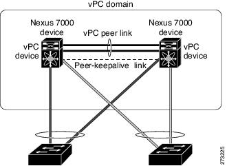
Virtual Port Channel (vPC)
A Virtual Port Channel (vPC) allows links that are physically connected to two different Cisco Nexus 7000 or Cisco Nexus 5000 series network elements to appear as a single port channel by a third device as shown in Figure 27-1. The third device can be a switch, server, or any other networking device that supports port channels. A vPC can provide Layer 2 multipathing, which allows you to create redundancy and increase bisectional bandwidth by enabling multiple parallel paths between nodes and allowing load balancing traffic. You can use only Layer 2 port channels in the vPC.
Figure 27-1 vPC Architecture
A vPC consists of the following components:
•
•
•
•
A vPC domain is associated to a single Virtual Device Context (VDC), so all vPC interfaces belonging to a given vPC domain must be defined in the same VDC. You must have a separate vPC peer link and peer keepalive link infrastructure for each VDC deployed. Consolidating a vPC pair (two vPC peer devices of the same domain) in two VDCs of the same physical device is not supported. The vPC peer link must use 10-Gigabit Ethernet ports for both ends of the link; otherwise, the link will not be formed.
A vPC provides the following benefits:
•
•
•
•
•
•
•
Prime Network supports vPC on Cisco Nexus 5000 series and Cisco Nexus 7000 series network elements.
This topic contains the following sections:
•
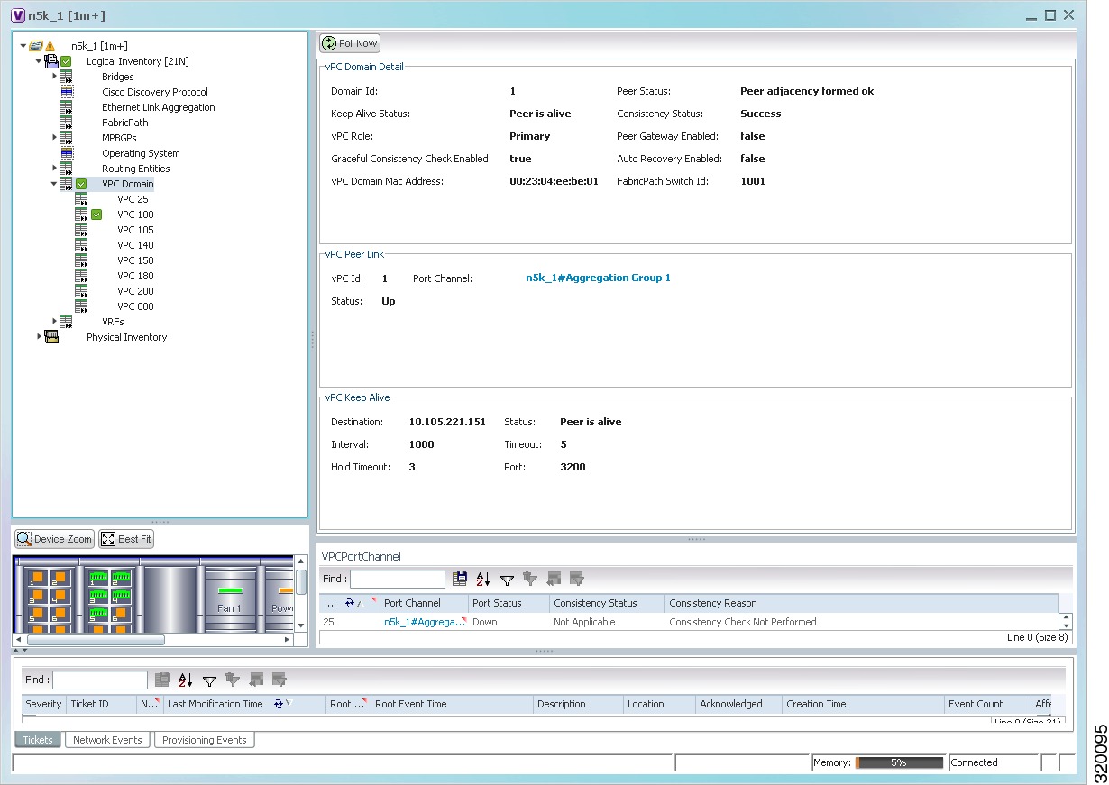
Viewing Virtual Port Channel Configuration
To view the vPC configuration details in Prime Network Vision:
Step 1
Step 2
Figure 27-2 vPC Domain in Logical Inventory
Table 27-2 describes the vPC domain details.
Viewing vPC Configuration
The following commands can be launched from the inventory by right-clicking VPC Domain and choosing Commands > Show. Before executing any commands, you can preview them and view the results. If desired, you can also schedule the commands. To find out if a device supports these commands, see the Cisco Prime Network 3.10 Supported Cisco VNEs.
Note
Cisco FabricPath
Cisco FabricPath is an innovation in Cisco NX-OS software that brings the stability and scalability of routing to Layer 2. It provides a foundation to build a scalable fabric—a network that itself looks like a single virtual switch from the perspective of its users. The switched domain does not have to be segmented anymore, providing data center-wide workload mobility. Because traffic is no longer forwarded along a spanning tree, the bisectional bandwidth of the network is not limited, and massive scalability is possible.
Cisco FabricPath introduces an entirely new Layer 2 data plane by encapsulating the frames entering the fabric with a header that consists of routable source and destination addresses. These addresses are the address of the switch on which the frame was received and the address of the destination switch to which the frame is heading. From there, the frame is routed until it is reaches the remote switch, where it is de-encapsulated and delivered in its original Ethernet format.
Cisco FabricPath provides the following features:
•
•
•
•
The system randomly assigns a unique switch ID to each device that is enabled with FabricPath. After you enable FabricPath on the devices, you can configure an Ethernet interface or a port channel interface as a FabricPath interface. If one member of the port channel is in FabricPath mode, then all the other members will also be in FabricPath mode. After you configure the interface as a FabricPath interface, it automatically becomes a trunk port, capable of carrying traffic for multiple Virtual Local Area Networks (VLANs).
Prime Network supports Cisco FabricPath on Cisco Nexus 5000 series and Cisco Nexus 7000 series network elements. Figure 27-3 shows a Cisco FabricPath architecture.
Figure 27-3 Cisco FabricPath Architecture
This topic contains the following sections:
•
•
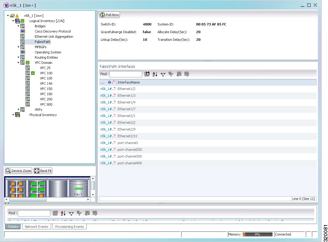
Viewing Cisco FabricPath Configuration
To view the FabricPath configuration in Prime Network Vision:
Step 1
Step 2
Figure 27-4 Cisco FabricPath Node in Logical Inventory
Table 27-3 describes the FabricPath configuration details.
Monitoring Cisco FabricPath Configuration
The following commands can be launched from the inventory by right-clicking FabricPath and choosing Commands > Show. Before executing any commands, you can preview them and view the results. If desired, you can also schedule the commands. To find out if a device supports these commands, see the Cisco Prime Network 3.10 Supported Cisco VNEs.
Note
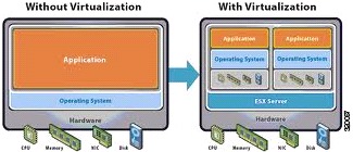
Virtualization
Virtualization is a concept of creating a virtual version of any resource, such as hardware platform, operating system, storage device, or network resources, as shown in Figure 27-5. It provides a layer of abstraction between computing, storage and networking hardware, and the applications running on it. Virtual infrastructure gives administrators the advantage of managing pooled resources across the enterprise, allowing IT managers to be more responsive to dynamic organizational needs and to better leverage infrastructure investments.
Figure 27-5 Virtualization Concept
The various components of virtualization are:
Hypervisor (Host Server)
A hypervisor, also called a blade server, a virtual machine manager, or a host server, is a program that allows multiple operating systems to share a single hardware host. Each operating system appears to have the host's processor, memory, and other resources all to itself. However, the hypervisor is actually controlling the host processor and resources, allocating what is needed to each operating system in turn and making sure that the guest operating systems (called virtual machines) do not disrupt each other.
Virtual Machine
A virtual representation of a real machine using software that provides an operating environment, which can run or host a guest operating system.
Guest Operating System
An operating system running in a virtual machine environment that would otherwise run directly on a separate physical system.
Data Store
A data store represents a storage location for virtual machine files. It can be a Virtual Machine File System (VMFS) volume, a directory on Network Attached Storage, or a local file system path.
Data Center
Data Center serves as a container for hosts, virtual machines, networks, and data stores.
Prime Network supports virtualization on Cisco UCS network element.
The following topics explain how to view and monitor virtual data center properties in Prime Network Vision:
•
•
•
Viewing Virtual Data Centers
To view the virtual data centers in the logical inventory:
Step 1
Step 2
Table 27-4 describes the virtual data center properties.
Step 3
Viewing the Data Stores of a Data Center
To view the details of data stores available for a data center:
Step 1
Step 2
Table 27-5 describes the data store properties.
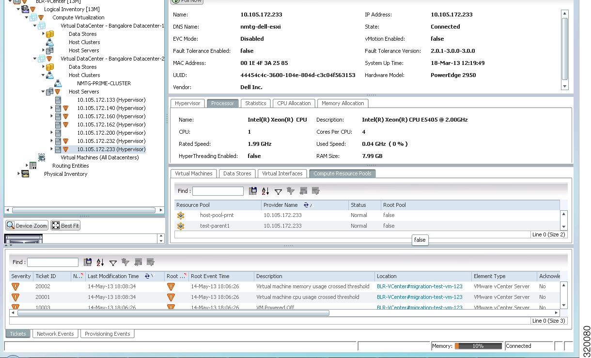
Viewing the Host Servers of a Data Center
To view the host centers of a data center:
Step 1
Step 2
Figure 27-6 Host Server Details
Table 27-6 describes the host server details.
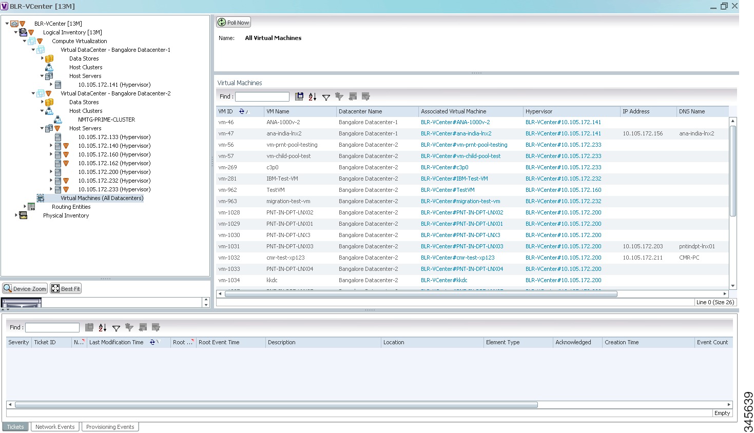
Viewing the Virtual Machines of a Data Center
To view the virtual machines for a data center:
Step 1
Step 2
Figure 27-7 Virtual Machine Details
Table 27-7 describes the virtual machine details available in the list.
Step 3
Table 27-8 describes the properties of the virtual machine.