-
Cisco Prime Network User Guide, 3.10
-
Preface
-
The Prime Network GUI Clients
-
Working with the Cisco Prime Network Vision Client
-
Viewing and Managing NE Properties
-
Device Configurations and Software Images
-
Working with Prime Network Vision Maps
-
Working with Links
-
Labeling NEs Using Business Tags
-
Working with the Prime Network Events Client
-
Tracking Faults Using Prime Network Events
-
Working with Tickets in Cisco Prime Network Vision
-
Working with Reports
-
Using Cisco PathTracer to Diagnose Problems
-
Monitoring Carrier Ethernet Services
-
Monitoring Carrier Grade NAT Properties
-
Monitoring DWDM Properties
-
Viewing Ethernet Operations, Administration, and Maintenance Tool Properties
-
Monitoring Y.1731 IPSLA Configuration
-
IPv6 and IPv6 VPN over MPLS
-
Monitoring MPLS Services
-
Viewing IP and MPLS Multicast Configurations
-
Monitoring MToP Services
-
Viewing and Managing SBCs
-
Monitoring AAA Configurations
-
Monitoring IP Pools
-
Monitoring BNG Configurations
-
Monitoring Mobile Technologies
-
Monitoring Data Center Configurations
-
Icon and Button Reference
-
Glossary
-
Index
-
 Feedback
Table Of Contents
User Roles Required to View SBC Properties
Viewing SBC Properties in Logical Inventory
Viewing Media Address Properties
SBC Configuration and Monitoring Commands
Add, Update, and Delete SBC Components
Viewing and Managing SBCs
This chapter identifies and describes the properties for Session Border Controllers (SBCs) that appear in Cisco Prime Network Vision (Prime Network Vision) logical inventory. It also describes commands you can run to manage SBCs.
Session Border Controllers (SBCs) control and manage real-time multimedia traffic flows between IP network borders, handling signaling, and media. SBCs perform native IP interconnection functions required for real-time communications such as admission control, firewall traversal, accounting, signaling interworking, and quality-of-service (QoS) management. This includes:
•
Protocol and media interworking
•
•
•
•
•
The Cisco Prime Network platform provides fault management, configuration, and performance monitoring for SBC services. Prime Network SBC commands allow you to configure SBC components.
An SBC consists of combined DBE and SBE functionality:
•
•
In addition, the SBC can operate in the following deployment models:
•
•
Note
The following topics describe the SBC properties that are displayed in Prime Network Vision logical inventory:
•
•
•
User Roles Required to View SBC Properties
This topic identifies the GUI default permission or scope security level that is required to view SBC properties in Prime Network Vision. Prime Network determines whether you are authorized to perform a task as follows:
•
•
For more information on user authorization, see the Cisco Prime Network 3.10 Administrator Guide.
The following tables identify the tasks that you can perform:
•
•
By default, users with the Administrator role have access to all managed elements. To change the Administrator user scope, see the topic on device scopes in the Cisco Prime Network 3.10 Administrator Guide.
Viewing SBC Properties in Logical Inventory
To view SBC properties in Prime Network Vision logical inventory, right-click the element configured for SBC, then choose Inventory > Logical Inventory > Session Border Controller.
The SBC properties are displayed as shown in Figure 22-1.
Figure 22-1 SBC Properties in Logical Inventory
Table 22-3 describes the general SBC properties displayed in logical inventory.
Viewing SBC DBE Properties
The DBE controls media packet access to the network, provides differentiated services and QoS for different media streams, and prevents service theft.
To view SBC DBE properties, choose Logical Inventory > Session Border Controller > DBE.
Table 22-4 describes the DBE properties that appear in logical inventory.
Viewing Media Address Properties
A DBE uses a pool of sequential IPv4 media addresses as local media addresses.
To view SBC media address properties, choose Logical Inventory > Session Border Controller > DBE > Media Address.
Table 22-5 describes the SBC media address properties that are displayed in logical inventory.
Viewing VDBE H.248 Properties
To view VDBE H.248 properties, choose Logical Inventory > Session Border Controller > DBE > VDBE.
Table 22-6 describes the VDBE H.248 properties that are displayed in logical inventory.
Viewing SBC SBE Properties
The SBE controls the access of VoIP signaling messages to the network core and manipulates the contents of these messages. It does this by acting as a SIP B2BUA or H.323 gateway.
To view SBC SBE properties, choose Logical Inventory > Session Border Controller > SBE.
Table 22-7 describes the information displayed in logical inventory for an SBE.
Viewing AAA Properties
For devices that support local and remote billing, the SBC can send billing records to a AAA server using the RADIUS protocol.
To view AAA properties, choose Logical Inventory > Session Border Controller > SBE > AAA.
Table 22-8 describes the AAA properties that appear in logical inventory for the SBC SBE.
Viewing H.248 Properties
The H.248 interface is used for signaling between an SBE and a DBE in distributed mode and between an SBE and a transcoding media gateway. The SBE or SBC acts as an H.248 MGC, and the transcoding device acts as an H.248 media gateway. The connection between the MGC and the media gateway is an H.248 link.
To view H.248 properties, choose Logical Inventory > Session Border Controller > H248.
Table 22-9 describes the H.248 properties that appear in logical inventory for the SBC SBE.
Viewing Policy Properties
An SBC policy is a set of rules that define how the SBC treats different kinds of VoIP events. An SBC policy allows control of the VoIP signaling and media that pass through the SBC at an application level.
A policy set is a group of policies that can be active on the SBC at any one time. If a policy set is active, the SBC uses the rules defined within it to apply policy to events. Multiple policies can be set on a single SBC.
To view policy properties, choose Logical Inventory > Session Border Controller > Policy.
Table 22-10 describes the policy properties that appear in logical inventory for the SBC SBE.
Viewing SIP Properties
To view SIP properties, choose Logical Inventory > Session Border Controller > SIP.
Table 22-11 describes the SIP entries that appear in logical inventory for the SBC SBE.
SBC Configuration and Monitoring Commands
The following commands can be launched from the inventory by right-clicking the appropriate node and selecting Commands. Before executing any commands, you can preview them and view the results. If desired, you can also schedule the commands. To find out if a device supports these commands, see the Cisco Prime Network 3.10 Supported Cisco VNEs.
Note
Commands are described in these topics:
•
Note
Add, Update, and Delete SBC Components
You can configure the following SBC components using the commands described in this section.
SIP Adjacencies
•
•
Add and Update SIP Adjacencies
Use this procedure to add an SIP adjacency or update an existing SIP adjacency.
Step 1
Step 2
•
•
•
Step 3
Step 4
Step 5
Step 6
Step 7
Step 8
Step 9
Step 10
Step 11
Add, Update, Delete an Outbound Authentican Realm in a SIP Adjacency
Use the Add Sip Adjacency Outbound AuthRealm command to add a SIP adjacency outbound authentication realm.
Step 1
Step 2
Step 3
•
•
•
Step 4
Step 5
Delete a SIP Adjacency
Step 1
Step 2
Step 3
Step 4
Step 5
SIP Header Profiles
Add, Update, Delete a SIP Header Profile
Use the Add SIP Header Profile command to add a SIP header profile.
Note
Step 1
Step 2
•
•
•
Step 3
Step 4
Note
Step 5
Add or Delete a Header from an Existing SIP Header Profile
Use the Add Header command to add a header to an existing header profile.
Step 1
Step 2
Step 3
•
•
Step 4
Step 5
Add, Update, Delete an Entry in a SIP Header Profile
Use the Add SIP Header Profile Entry command to add an entry to an existing SIP header profile header.
Step 1
Step 2
•
•
•
Step 3
Step 4
Adding a Condition to a SIP Header Profile Header Entry
Use the Add SIP Header Profile Condition command to add a condition to a SIP header profile header.
Step 1
Step 2
Step 3
Step 4
Step 5
Step 6
Step 7
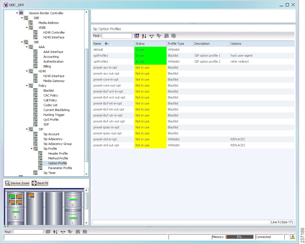
SIP Option Profiles
Add, Update, Delete a SIP Option Profile
Step 1
Step 2
•
•
•
Step 3
Step 4
Step 5
Add, Delete a SIP Parameter Profile
Use the Add SIP Parameter Profile command to add a SIP parameter profile.
Step 1
Step 2
•
•
Step 3
Profile Name
The name of the SIP parameter profile.
Description
The description of the SIP parameter profile.
Step 4
Add, Update, Delete Parameter in SIP Parameter Profiles
Step 1
Step 2
Step 3
•
•
•
Step 4
Step 5
Blacklists
Add, Delete a Blacklist
Step 1
Step 2
•
•
Step 3
Step 4
Add, Delete, Update a Blacklist Reason
Use the Add Blacklist Reason command to add a blacklist reason.
Step 1
Step 2
Step 3
•
•
•
Step 4
If you are updating and existing blacklist reason, you can edit the Blacklist Period, Trigger Period, and Trigger Size entries.
Step 5
CAC Policies
Add, Update, Delete a CAC Policy Set
Use the Add CAC Policy Set command to add a Call Admission Control (CAC) policy set.
Step 1
Step 2
•
•
•
Step 3
Step 4
Note
Step 5
Add, Update, Delete a CAC Policy Table
Use the Add CAC Policy Table command to add a CAC policy table to an existing CAC policy set.
Step 1
Step 2
Step 3
•
•
•
Step 4
Step 5
Add, Update, Delete CAC Rule Entry in a CAC Policy Table
Use the Add CAC Policy Entry command to add a CAC rule entry to an existing CAC policy table.
Step 1
Step 2
Step 3
Step 4
•
•
•
Step 5
Step 6
Step 7
Step 8
Step 9
Call Policies
Add, Update, Delete a Call Policy Set
Use the Add Call Policy Set command to add a new call policy set.
Note
Step 1
Step 2
•
•
•
Step 3
Step 4
You can add three entries to the call policy table. For details about adding more entries, see Add, Update, Delete a Call Rule Entry in a Call Policy Table.
Step 5
Add, Update, Delete Call Policy Tables
Use the Add Call Policy Table command to add a call policy table to an existing call policy set.
Step 1
Step 2
Step 3
•
•
•
Step 4
Step 5
Add, Update, Delete a Call Rule Entry in a Call Policy Table
Use the Add Call Rule Entry command to add an entry to an existing call policy table.
Step 1
Step 2
Step 3
Step 4
•
•
•
Step 5
Step 6
Codec Lists
Add, Delete a Codec List
Use the Add Codec List command to add a codec list.
Step 1
Step 2
•
•
Step 3
Name
The name of the codec list.
Description
The description of the codec list.
Step 4
Add, Update, Delete an Entry in a Codec List
Step 1
Step 2
Step 3
•
•
•
Step 4
Step 5
Media Addresses
Adding a Media Address or Media Address DBE
Step 1
Step 2
•
•
Step 3
Step 4
Delete a Media Address
Step 1
Step 2
Step 3
Step 4
Qos Profiles
Add, Update, Delete a QoS Profile
Use the Add QoS Profile command to add a QoS profile.
Step 1
Step 2
•
•
•
Step 3
Step 4
SBC Show Commands
The following commands can be launched from the inventory by right-clicking an SBC node and selecting Commands. Before executing any commands, you can preview them and view the results. If desired, you can also schedule the commands. To find out if a device supports these commands, see the Cisco Prime Network 3.10 Supported Cisco VNEs.
Input is not required; all of the commands are run from the launch point.
•
•
•
•
•
•
•
•
•
•
•
•