-
Cisco Prime Network User Guide, 3.10
-
Preface
-
The Prime Network GUI Clients
-
Working with the Cisco Prime Network Vision Client
-
Viewing and Managing NE Properties
-
Device Configurations and Software Images
-
Working with Prime Network Vision Maps
-
Working with Links
-
Labeling NEs Using Business Tags
-
Working with the Prime Network Events Client
-
Tracking Faults Using Prime Network Events
-
Working with Tickets in Cisco Prime Network Vision
-
Working with Reports
-
Using Cisco PathTracer to Diagnose Problems
-
Monitoring Carrier Ethernet Services
-
Monitoring Carrier Grade NAT Properties
-
Monitoring DWDM Properties
-
Viewing Ethernet Operations, Administration, and Maintenance Tool Properties
-
Monitoring Y.1731 IPSLA Configuration
-
IPv6 and IPv6 VPN over MPLS
-
Monitoring MPLS Services
-
Viewing IP and MPLS Multicast Configurations
-
Monitoring MToP Services
-
Viewing and Managing SBCs
-
Monitoring AAA Configurations
-
Monitoring IP Pools
-
Monitoring BNG Configurations
-
Monitoring Mobile Technologies
-
Monitoring Data Center Configurations
-
Icon and Button Reference
-
Glossary
-
Index
-
 Feedback
Table Of Contents
Viewing IP and MPLS Multicast Configurations
IP and MPLS Multicast Configuration - An Overview
User Roles Required to View IP and Multicast Configurations
Viewing the Multicast Configurations
Viewing the Address Family (IPv4) Profile
Viewing the Address Family (IPv6) Profile
Viewing IP and MPLS Multicast Configurations
These topics provide an overview of the IP Multicast technology and describe how to view IP and multicast configurations in Prime Network Vision:
•
IP and MPLS Multicast Configuration - An Overview
•
•
IP and MPLS Multicast Configuration - An Overview
IP Multicast is a bandwidth-conserving technology that reduces traffic by simultaneously delivering a single stream of information to thousands of corporate recipients and homes. Applications that take advantage of multicast include video conferences, corporate communications, distance learning, and distribution of software, stock quotes, and news.
IP Multicast delivers source traffic to multiple receivers without adding any additional burden on the source or the receivers while using the least network bandwidth of any competing technology. Multicast packets are replicated in the network by Cisco routers enabled with Protocol Independent Multicast (PIM), Multicast Label Distribution Protocol (MLDP) and other supporting multicast protocols resulting in the most efficient delivery of data to multiple receivers possible.
Multicast is based on the concept of a group. An arbitrary group of receivers expresses an interest in receiving a particular data stream. This group does not have any physical or geographical boundaries—the hosts can be located anywhere on the Internet. Hosts that are interested in receiving data flowing to a particular group must join the group using Internet Group Management Protocol (IGMP). Hosts must be a member of the group to receive the data stream.
In Prime Network, IP and multicast support is available for the following network elements:
•
•
•
User Roles Required to View IP and Multicast Configurations
This topic identifies the roles that are required to work with IP and Multicast Support. Prime Network determines whether you are authorized to perform a task as follows:
•
•
For more information on user authorization, see the topic on device scopes in the Cisco Prime Network 3.10 Administrator Guide.
Viewing the Multicast Configurations
This topic contains the following sections:
Viewing Multicast Node
To view the Multicast node:
Step 1
Step 2
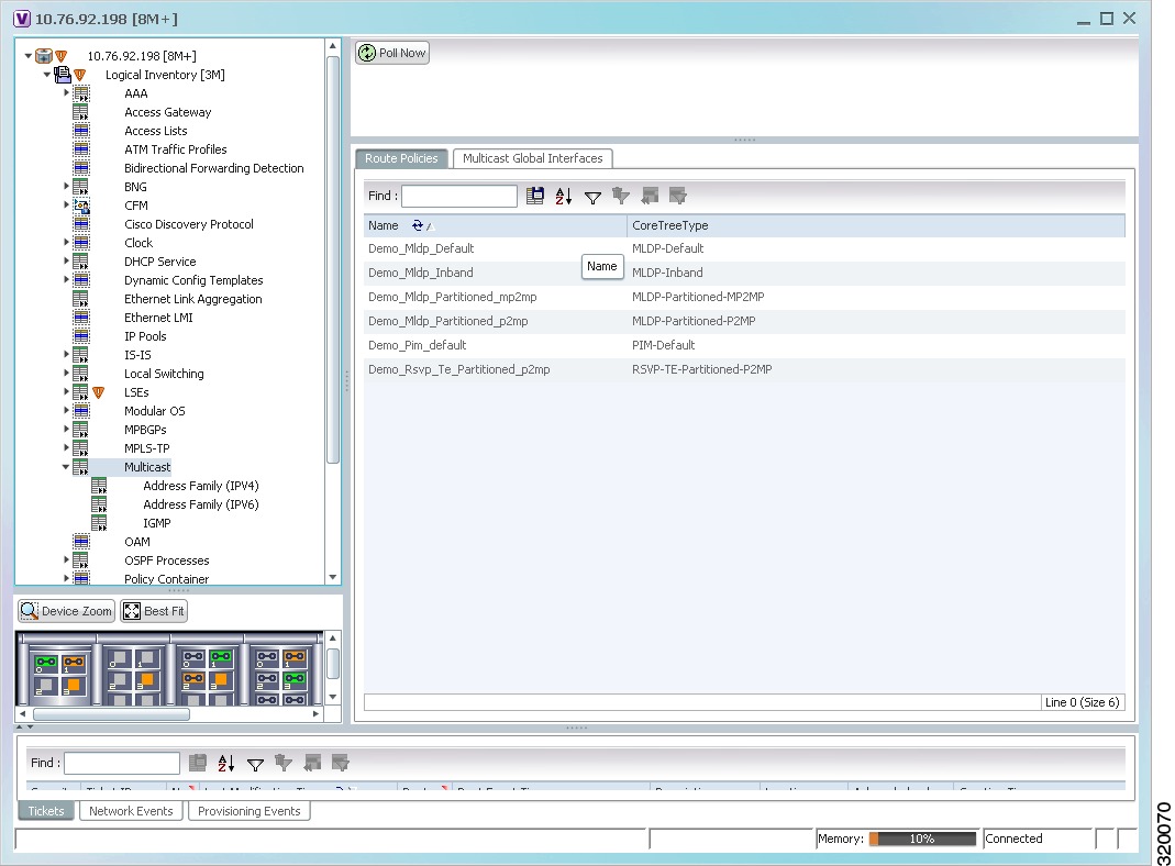
Figure 20-1
Multicast Content Pane
Table 20-2 describes the fields that are displayed in the Route Policies tab.
Viewing Multicast Protocols
The following Multicast protocols are available in Prime Network:
•
•
•
•
Viewing the Address Family (IPv4) Profile
To view the Address Family (IPv4) profile:
Step 1
Step 2
Table 20-3 describes the fields that are displayed in the Address Family (IPV4) profile.
Viewing the Address Family (IPv6) Profile
To view the Address Family (IPv6) profile:
Step 1
Step 2
Table 20-4 describes the fields that are displayed in the Address Family (IPV6) profile.
Viewing the IGMP profile
The IGMP runs between hosts and their immediately neighboring multicast routers. The mechanisms of the protocol allow a host to inform its local router that it wishes to receive transmissions addressed to a specific multicast group. Also, routers periodically query the LAN to determine if known group members are still active. If there is more than one router on the LAN performing IP multicasting, one of the routers is elected querier and assumes the responsibility of querying the LAN for group members. Based on the group membership information learned from the IGMP, a router is able to determine which (if any) multicast traffic needs to be forwarded to each of its leaf sub networks. Multicast routers use this information, in conjunction with a multicast routing protocol, to support IP multicasting across the Internet.
There are three versions of IGMP:
•
•
•
To view the IGMP profile:
Step 1
Step 2
Table 20-5 describes the fields that are displayed in the IGMP profile.
Viewing the PIM Profile
PIM is a family of multicast routing protocols for Internet Protocol (IP) networks that provide one-to-many and many-to-many distribution of data over a LAN, WAN or the Internet. It is termed protocol-independent because PIM does not include its own topology discovery mechanism, but instead uses routing information supplied by other traditional routing protocols such as the Routing Information Protocol, Open Shortest Path First, Border Gateway Protocol and Multicast Source Discovery Protocol. There are four variants of PIM:
•
•
•
•
Although PIM is called a multicast routing protocol, it actually uses the unicast routing table to perform the Reverse Path Forwarding (RPF) check function instead of building up a completely unrelated multicast routing table. PIM does not send and receive multicast routing updates between routers like other routing protocols.
To view the PIM profile:
Step 1
Step 2
Table 20-6 describes the fields that are displayed in the PIM profile.
Multicast Label Switching
Prime Network provides multicast support for MPLS services.
For more information on multicast label switching, see Multicast Label Switching.
Multicast Routing Entities
Prime Network provides multicast support for routing entities. If you have configured multicast route information for a VRF, Prime Network displays a separate tab for the related VRF wherein you can view the multicast routing information.
For details on multicast routing entities, see Viewing Routing Entities and Viewing VRF Properties.