Feedback
Table Of Contents
Capturing and Decoding Packet Data
Capturing Using an Address Filter
Capturing Using a Protocol Filter
Capturing Using a Custom Filter
Using Alarm-Triggered Captures
Viewing Packet Decode Information
Browsing Packets in the Packet Decoder
Filtering Packets Displayed in the Packet Decoder
Viewing Detailed Protocol Decode Information
Hardware Assisted Capture Sessions
Configuring the Hardware Assisted Capture Session
Renaming or Merging Capture Files
Creating Custom Capture Filters
Tips for Creating Custom Capture Filter Expressions
Editing Custom Capture Filters
Deleting Custom Capture Filters
Creating Custom Display Filters
Tips for Creating Custom Decode Filter Expressions
Editing Custom Display Filters
Deleting Custom Display Filters
Capturing and Decoding Packet Data
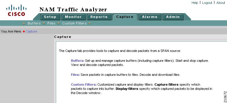
The Capture tab allows you to set up multiple buffers for capturing, filtering, and decoding packet data, manage the data in a file control system, and display the contents of the packets.
The Capture Tab (Figure 6-1) shows the options available for capturing and decoding packet data.
Figure 6-1 Capture Tab
From the Capture tab, you can select three options:
Use the Buffers option to access the basic operations for capturing, viewing and decoding packet data on the NAM.
The Cisco NAM 2200 Series appliances can also configure Hardware Assisted Capture.
Use the Files option to save, decode, or download files.
Use the Custom Filters option to create customized capture and display filters.
Note
NAM 4.1 supports IPv6 for all capture functionality.
Buffers
Note
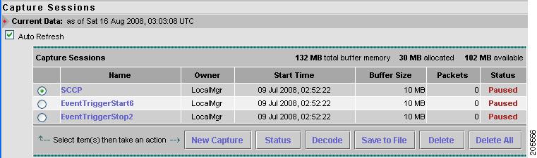
The Capture Buffers (Figure 6-2) window shows the list of capture buffers. You can configure multiple capture buffers and multiple automatic capture buffers.
Note
Figure 6-2 Capture Buffers
Capture Buffer Fields, Table 6-1, describes the Capture Buffers fields.
Capture Buffer Operations (Table 6-2) describes the operations that you can perform from the Capture Buffers window.
Table 6-2 Capture Buffer Operations
New Capture
Click to create a new capture buffer. See Configuring Capture Settings.
Status
Click to display status and settings of selected capture.
Decode
Click to view decoded packets. See Viewing Packet Decode Information.
Save to File
Click to save a buffer to a file on the NAM hard disk. See Files.
Delete
Click to delete a buffer.
Delete All
Click to delete all buffers.
Configuring Capture Settings
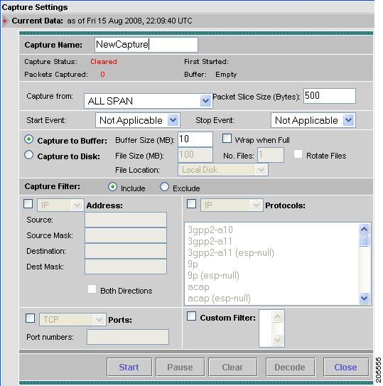
The Capture Settings window enables you to configure the settings for a new capture and control the capture process. You can also configure capture filters to narrow down the packets to be captured.
To configure a new capture buffer:
Step 1
Step 2
The NAM Traffic Analyzer displays the Capture Settings (Figure 6-3) window. The Capture Settings window provides a field for you to enter a name for the capture and four status indicators described in Table 6-3.
Figure 6-3 Capture Settings
Step 3
Table 6-4 Capture Settings Fields
Capture Name
Name of the capture
Enter a capture name.
Capture from
Data source from which to capture packets
Choose an entry from the list.
Start Event
Alarm event that starts the capture
You can configure Alarm Events from the Setup > Alarms >
Alarm Event window. When an alarm event theshold is crossed, the alarm event starts or stops the capture session.Note
Stop Event
Alarm event that stops the capture
Packet Slice Size
The slice size in bytes; used to limit the size of the captured packets.
Enter a value of 64 or higher. Enter zero (0) to not perform slicing.
If you have a small buffer but want to capture as many packets as possible, use a small slice size.
If the packet size is larger than the specified slice size, the packet is sliced before it is saved in the capture buffer. For example, if the packet is 1000 bytes and slice size is 200 bytes, only the first 200 bytes of the packet is stored in the capture buffer.
Capture to Buffer
Check to store captures in buffers
Enter values for Buffer Size and Wrap when Full.
Buffer Size
Size of the capture buffer in MB.
Use this field to define the buffer size for this capture. Enter a number from 1 up to your platform maximum. If system memory is low, the actual buffer size allocated might be less than the number specified here. See Table 6-5 for maximum buffer sizes for each NAM platform.
Wrap when Full
Check to wrap data in buffer when it exceeds buffer size
Check Wrap when Full to enable continuous capture.
Note
Capture to Disk
Check to store captures in files
Enter values for File Size and No. Files.
Note
File Size (MB)
Maximum size of each capture file
File size can be from 1 to 2 GB or up to 10 GB for the NAM appliances.
File Location
Choose an option from the pull-down menu.
Local disk is the default, or choose a previously configured remote storage location. You can add (NFS and iSCSI) remote storage locations by clicking Admin > System and choosing Capture Data Storage from the Content menu.
No. Files
Number of files to use for continuous capture
Number of files can be from 1 to 200.
Rotate Files
Check to rotate files in continuous capture
Available only for remote storage or NAM 2200 Series appliances
See section Capture Data Storage, page 2-19, for information about configuring remote storage.
Capture Filter: Include
Include filters capture only packets that match the filter conditions (recommended)
Capture Filter: Exclude
Exclude filters capture packets that exclude the filter conditions (recommended)
Table 6-5 lists the hardware platforms NAM 4.1 supports and their maximum buffer size.
Step 4
This type of capture stores packet data up to the size you set in Buffer Size. If you do not check Wrap when Full, capture will end when amount of data reaches size of buffer.
Step 5
When capturing to multiple files, a suffix is added to the file name. For example, the first file for a capture named CaptureA would be labeled as CaptureA_1 the second CaptureA_2, and so on.
Note
Step 6
The Rotate Files option can only be used with remote storage or the NAM 2200 Series appliance's local disk. See the section Capture Data Storage, page 2-19, for information about configuring remote storage.
Note
Step 7
Include filters capture only packets that match the filter conditions. Exclude captures packets that exclude the filter conditions.
Step 8
•
•
•
•
For more information on creating and editing a custom capture filter, see the "Custom Capture Filters" section.
Step 9
For example, to capture only HTTP and HTTPS packets in the 111.122 Class B network, do the following:
Step 1
Step 2
Step 3
Step 4
Step 5
Step 6
Step 7
Step 8
Capturing Using an Address Filter
If you selected the Address check box, enter information in the Capture Settings Address Filter Dialog Box, Table 6-7, as appropriate.
Note
Capturing Using a Protocol Filter
If you selected the Protocol check box, select one or more protocols to capture from the drop-down list.
Use Shift + Click to select multiple protocols.
Capturing Using a Port Filter
From the Capture Settings window, select the Ports check box and enter one or more ports separated by commas.
Capturing Using a Custom Filter
Step 1
Note
Step 2
Note
To view or edit the selected custom capture filter, choose Custom Filters > Capture Filters.
Using Alarm-Triggered Captures
You can configure multiple alarm-triggered captures that start and stop automatically by alarm events you define.
To set up an alarm-triggered capture:
Step 1
Configure an Alarm Event for the type of event for which you want to capture data. See Setting Up Alarm Events, page 3-82, for more information.
Step 2
Configure the threshold of parameters of interest in the associated Alarm Event. See Setting Alarm Thresholds, page 3-84, for more information.
Step 3
Choose the Start Event and/or the Stop Event for the associated Alarm Event. See Configuring Capture Settings, for more information.
Viewing Packet Decode Information
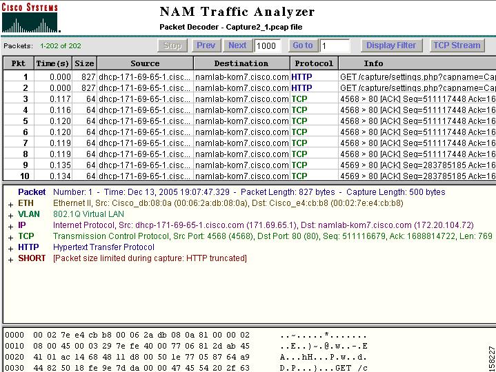
After some packets have been captured in the buffer, you can use the Packet Decoder to view the packet contents.
The Packet Decoder window has four parts:
•
•
•
•
To view packet decode information:
Step 1
Step 2
The Packet Decoder window displays as shown in Figure 6-4.
Figure 6-4 Packet Decoder Window
Table 6-8 describes the packet decoder operations.
Note
Table 6-8 Packet Decoder Operations
Stop
Stop packet loading
Prev
Load and decode the previous block of packets from the NAM
Next
Load and decode the next block of packets from the NAM
Go To
Load and decode a block of packets starting from the specified packet number.
Display Filter
Launch the Display Filter dialog. See Filtering Packets Displayed in the Packet Decoder.
TCP Stream
Follow the TCP stream of the selected TCP packet.
Note
Table 6-9 describes the information displayed in the packet browser pane.
Browsing Packets in the Packet Decoder
You can use the packet browser to browse the list of captured packets and do the following:
•
•
Note
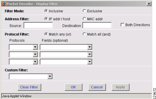
Filtering Packets Displayed in the Packet Decoder
To filter packets displayed in the packet decoder:
Step 1
The Packet Decoder - Display Filter Window (Figure 6-5) displays.
Figure 6-5 Packet Decoder - Display Filter Window
Step 2
•
–
–
•
–
–
–
–
–
•
–
or
–
–
Note
–
•
Step 3
Step 4
Step 5
Viewing Detailed Protocol Decode Information
To view detailed protocol information:
Step 1
Detailed information about that packet is displayed in the Protocol Decode and hexadecimal dump panes at the bottom of the window.
Note
Step 2
Note
Tip
•
•
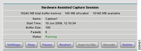
Hardware Assisted Capture Sessions
Note
Hardware Assisted Capture enables you to improve capture performance by providing hardware-specific filters to help you eliminate as much extraneous traffic as possible. The packets filtered out by hardware filters are not processed by the NAM and capture performance improves.
Click Capture > Buffers to view the status and settings of the hardware assisted capture feature of the Cisco NAM appliance. Figure 6-6 shows the Hardware Assisted Capture Sessions dialog box.
Figure 6-6 Hardware Assisted Capture Session
Click Settings to configure a hardware assisted capture session. The Capture Buffers window displays as shown in Figure 6-7. The settings are similar to the NAM software capture, except that the Hardware-Assisted Capture Session provides additional hardware and software filters.
Hardware Assisted Capture Session uses a combination of the hardware filters and the software filters you define. For filtering to be successful, you must match one of the hardware filters (if there are any) AND one of the software filters (if there are any). You can perform filtering without using both hardware and software filters.
Software filters add flexibility to your filtering, but a Hardware Assisted Capture Session is most efficient when you use only hardware filters. The less traffic requiring software filtering, the more efficient the filtering.
Use the other buttons on the Hardware Assisted Capture Session window for the following:
•
•
•
•
This option is enabled only when a capture session has been stopped or paused.
Note
•
This option is enabled only when a capture session has been stopped or paused.
•
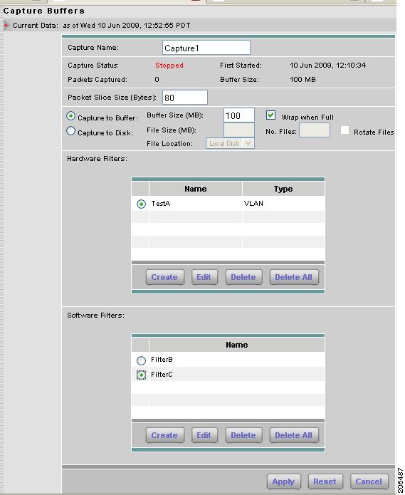
Configuring the Hardware Assisted Capture Session
The Capture Buffers window, shown in Figure 6-7, displays the status and settings of the Hardware-Assisted Capture if a capture has been defined.
Figure 6-7 Configuring Capture Buffers
Table 6-10 describes the fields of the Capture Buffers window. To configure a capture:
Step 1
Step 2
Step 3
•
•
Step 4
Depending on the type of filter, see one of the following:
Note
Step 5
Table 6-10 Capture Buffers Settings
Capture Name
Name of the capture
Enter a capture name.
Capture Status
The current status of the capture.
•
•
•
•
Packets Captured
The number of packets captured and stored in the capture buffer.
When the capture buffer is full and capture is in wrap-when-full mode, the number of packets captured may fluctuate as new packets arrive and old packets are discarded from the buffer.
First Started
Shows when the current capture started.
You can pause and restart the capture as many times as necessary. If you stop the capture and start a new capture, this field shows the start time of the new capture.
Buffer Size (MB)
Current buffer or file state
Currently allocated buffer size.
Packet Slice Size (Bytes)
The slice size in bytes; used to limit the size of the captured packets.
Enter a value of 64 or higher. Enter zero (0) to not perform slicing.
If you have a small buffer but want to capture as many packets as possible, use a small slice size.
If the packet size is larger than the specified slice size, the packet is sliced before it is saved in the capture buffer. For example, if the packet is 1000 bytes and slice size is 200 bytes, only the first 200 bytes of the packet is stored in the capture buffer.
Capture to Buffer
Default; captures to buffer that you define
Enter values for Buffer Size (MB) and click whether to Wrap when Full.
Buffer Size (MB)
Use this field to define the buffer size for this capture. Enter a number from 1 up to your platform maximum. If system memory is low, the actual buffer size allocated might be less than the number specified here. See Table 6-5 for maximum buffer sizes for each NAM platform.
Wrap when Full
Check to wrap data in buffer when it exceeds buffer size.
Check Wrap when Full to enable continuous capture.
Note
Capture to Disk
Check to store captures in files
Enter values for File Size and No. Files.
Note
File Size (MB)
Maximum size of each capture file
File size can be from 1 to 2 GB or up to 10 GB for the NAM appliances.
File Location
Choose an option from the pull-down menu.
Local disk is the default, or choose a previously configured remote storage location. You can add (NFS and iSCSI) remote storage locations by clicking Admin > System and choosing Capture Data Storage from the Content menu.
No. Files
Number of files to use for continuous capture
Number of files can be from 1 to 200.
Note
Rotate Files
Check to rotate files in continuous capture
Available only for remote storage or NAM 2200 Series appliances
See section Capture Data Storage, page 2-19, for information about configuring remote storage.
Hardware Filters:
Lists any hardware filters configured for a capture session.
Click a radio button to select one of the hardware filters in the list. Click Create to define hardware filters to use for the capture buffer session. See Configuring Hardware Filters.
Software Filters:
Lists any software filters configured for a capture session.
Click a radio button to select one of the software filters in the list. Click Create to define software filters to use for the capture buffer session. See Configuring Software Filters.
Configuring Hardware Filters
To configure a hardware filter:
Step 1
Step 2
Choose one of the following hardware filter types:
•
•
Step 3
Step 4
VLAN
To configure a VLAN hardware filter:
Step 1
Step 2
For better performance, use as narrow a range as possible. The VLAN ID can range from 1-4095.
Step 3
VLAN and IP
To configure a VLAN and IP hardware filter:
Step 1
Step 2
The VLAN ID can range from 1-4095.
Step 3
Note
If you do not enter values for the optional fields in steps 5 through 9, the filter will match based on the VLAN ID and the IP version. A filter with settings like this might be useful when trying to filter all IPv6 traffic from a specific VLAN.
Step 4
Step 5
Step 6
Step 7
Step 8
Step 9
IP
To configure an IP hardware filter:
Step 1
Step 2
Note
If you do not enter values in the optional fields for steps 3 through 7, the filter will match based only on IP Version. A filter using only the IP Version field and none of the optional fields might be useful when trying to filter IPv6 traffic.
Step 3
Step 4
Step 5
Step 6
Step 7
Step 8
IP and TCP/UDP
To configure an IP and TCP/UDP hardware filter:
Step 1
Step 2
Note
If you do not enter values in the optional fields for steps 3 through 9, an IP and TCP/UPD filter will match based on IP Version and IP Protocol (TCP or UDP). A filter with settings like this might be useful when the desired traffic is all IPv4 TCP. By adding a port, you can make an FTP Data filter (IPv4, TCP and Source Port 20).
Step 3
Step 4
Step 5
Step 6
Step 7
Step 8
Step 9
Step 10
IP and Payload Data
To configure an IP and Payload Data hardware filter:
Step 1
Step 2
Note
If you do not enter values in the optional fields for steps 3 through 6, the filter will match based on IP Version, IP Protocol (TCP or UDP), and Payload. A filter with settings like this might be useful when the desired traffic is all IPv4, TCP packets beginning with a specific payload signature.
Step 3
Step 4
Step 5
Step 6
Step 7
Step 8
The offset is relative to the beginning of the payload (Layer 5).
Step 9
Step 10
Step 11
Note
Step 12
Payload Data
To configure a Payload Data hardware filter:
Step 1
Step 2
Step 3
The offset is relative to the beginning of the payload (Layer 5).
Step 4
Step 5
Step 6
Only one payload segment (one row) is required. Be careful not to create overlapping payload segments. If overlapping segments have different values the filter will never match anything due to the inherent AND logic.
Step 7
Configuring Software Filters
To configure a software filter:
Step 1
Step 2
Step 3
Step 4
Step 5
Step 6
Step 7
You can define a software filter to filter based on any of the following:
•
•
•
Step 8
Step 9
Files
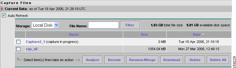
Use the Files option to analyze, decode, merge, download, or delete saved capture files. See the section Buffers and Table 6-2 for information about how to save capture buffers to files. You can download files from the Sniffer .enc or .pcap file formats. See Setting Global Preferences, page 3-94, for information about setting the Sniffer download file format.
Choose Capture > Files to display the Capture Files window (Figure 6-8).
Note
Figure 6-8 Capture Files Window
The Capture Files window provides the following options:
•
•
•
•
Note
•
•
Note
Analyzing Capture Files
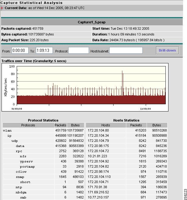
The Analyze button of the Capture Files window enables you to obtain different statistics including traffic rate (bytes/second) over a capture period, lists of hosts, conversations, and applications associated with network traffic. Figure 6-9 shows an example of the Capture Analysis window.
This window also enables you to drill down for a more detailed look at a particular set of network traffic. The pane above the Traffic over Time graph displays the time shown in the graph in the From: and To: fields. It also provides fields for Protocol and Host/subnet, and a Drill-Down button.
Each slice in the Traffic over Time graph displays the amount of traffic for the amount of time set in the Granularity of the capture file.
You can view more detail about a specific time frame by entering the time in the From: and To: fields and clicking Drill-Down. You can also drill down on a specific Protocol or Host/subnet address.
Figure 6-9 Capture Statistical Analysis Window
Table 6-11 describes the different areas of the capture analysis window.
Decoding Capture Files
Decoding capture files is described in section Viewing Packet Decode Information.
Renaming or Merging Capture Files
Use the Rename/Merge button to rename a single capture file or merge multiple capture files into one file.
Note
Renaming Capture Files
To rename a capture file:
Step 1
Step 2
Step 3
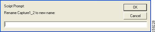
A dialog box displays and asks you to enter the new name for the selected capture file.
Figure 6-10 Rename Capture File Dialog Box
Step 4
Merging Capture Files
To merge multiple capture files into one capture file:
Step 1
Step 2
Step 3
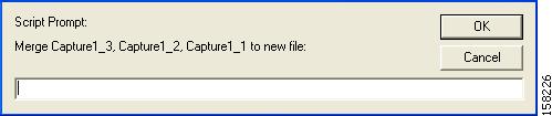
A dialog box displays and asks you to enter the new name for the merged capture files.
Note
Figure 6-11 Merging Capture Files Dialog Box
Step 4
The capture files are merged in timestamp order from oldest to most recent.
Downloading Capture Files
The following procedure describes how to download a capture file to your computer. You can only download one capture file at a time.
Step 1
Step 2
Step 3
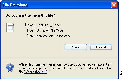
A File Download dialog box displays and asks "Do you want to save this file?"
Figure 6-12 Download Capture File Dialog Box
Step 4
A Save As dialog box opens and provides a way for you to rename and save the file at a location of your choice.
Deleting a Capture File
To delete a capture file:
Step 1
Step 2
Step 3
A dialog box displays and asks "Delete the following file(s)?" and displays the file name.
Step 4
Deleting All Capture Files
To delete all capture files at once:
Step 1
Step 2
Step 3
A dialog box displays and asks "Delete all capture file(s)?"
Step 4
Custom Capture Filters
You can use custom capture filters to create and save specialized filters to disregard everything except the information you are interested in when you capture data.
For more information about using custom filters when capturing data, see the "Capturing Using a Custom Filter" section.
See these topics for help setting up and managing custom capture filters:
•
•
•
Creating Custom Capture Filters
To create a custom capture filter:
Step 1
The Custom Capture Filters dialog box is displayed.
Step 2
The Custom Capture Filter Dialog Box (Table 6-12)displays.
Step 3
Table 6-12 Custom Capture Filter Dialog Box
Filter Name
Enter a name of the new filter.
Description
Brief description of the filter.
Enter a description from 1 to 35 characters.
Protocol
The protocol to match with the packet.
Choose the encapsulation from the drop-down list, then select the protocol.
Data
The data pattern to be matched with the packet. Use the Offset field to specify the starting location for the data to be checked.
Enter hh hh hh ..., where hh represents hexadecimal numbers from 0 to 9 or a to f.
For example, to designate the decimal value 15, use the hexadecimal value 0f. For the decimal value 255, use the hexadecimal value ff. For the decimal value 16, use the hexadecimal value 10. See Tips for Creating Custom Capture Filter Expressions, for more examples.
Leave blank if not applicable.
If the packet is too short and does not have enough data to match, the packet match fails.
Data Mask
The mask applied to the data matching.
Enter hh hh hh ..., where hh represents hexadecimal numbers from 0 to 9 or a to f.
Leave blank if all data bits are relevant.
If a bit in the Data Mask is set to 1, the corresponding bit in the packet is relevant in the matching algorithm.
If a bit in the Data Mask is set to 0, the corresponding bit in the packet is ignored.
If you do not specify the Data Mask, or if it is shorter than the Data field, the Data Mask is padded with "1" bits up to the length of the Data field. For example, if you enter a four-byte value in the Data field and leave the Data Mask field blank, that is the same as specifying a Data Mask of ff ff ff ff.
Data Not Mask
The mask applied to reverse data matching.
Enter hh hh hh ..., where hh represents hexadecimal numbers from 0 to 9 or a to f.
Leave blank for no reverse data matching.
For those bits in the Data Not Mask that are set to 0 (or not specified), the relevant bits in the packet must match the corresponding bit in the Data field.
For those bits in the Data Not Mask that are set to 1, at least one relevant bit in the packet must be different than the corresponding bit in the Data field.
If you do not specify the Data Not Mask, or if it is shorter than the Data field, the Data Not Mask is padded with "0" bits up to the length of the Data field.
Offset
Enter a decimal number, the offset (in bytes, from the Base) where packet data-matching begins.
This offset applies to the Data, Data Mask, and Data Not Mask fields.
Base
Choose absolute or a protocol, the base from which the offset is calculated.
If you select absolute, the offset is calculated from the absolute beginning of the packet (the beginning of the Ethernet frame). You must account for an 802.1q header when calculating an offset for NAM-1 and NAM-2 devices.
If you select protocol, the offset is calculated from the beginning of the protocol portion of the packet. If the packet does not contain the protocol, the packet fails this match.
Status
The status to match with the packet.
Enter a number from 0 to 65535; leave blank if not applicable.
For Ethernet packet captures, the status bits are:
Bit 0—Packet is longer than 1518 octets.
Bit 1—Packet is shorter than 64 octets.
Bit 2—CRC or alignment error.
For example, an Ethernet fragment has a status value of 6 (bits 1 and 2 set).
Status Mask
The mask applied to the status matching. Enter a number from 0 to 65535; leave blank if all status bits are relevant.
If a Status Mask bit is set to 1, the corresponding bit in the packet status is relevant in the matching algorithm.
If a Status Mask bit is set to 0, the corresponding bit in the packet status is ignored.
If you do not specify a Status Mask, or if it is shorter than the Status field, the Status Mask is padded with "1" bits up to the length of the Status field.
Status Not Mask
Enter a number from 0 to 65535, the mask applied to reverse status matching.
Leave blank for no reverse status matching.
For those bits in the Status Not Mask that are set to 0 (or not specified), the relevant status bits of the packet must match the corresponding bit in the Status field.
For those bits in the Status Not Mask that are set to 1, at least one relevant bit of the status packet must be different than the corresponding bit in the Status field.
If you do not specify a Status Not Mask, it is padded with "0" bits.
Step 4
Tips for Creating Custom Capture Filter Expressions
The TOS value is stored in byte 1 (the second byte) in the IP header. To match the IP packet with a TOS value of 16 (0x10), enter:
Data—10
Offset—1
Base—IPWith nothing in the Data Mask, its effective value is ff.
The source address of an IP packet is stored in bytes 12 to 15 in the IP header. To match IP packets with a source address of 15.16.17.18, enter:
Data—0f 10 11 12
Offset—12
Base—IPTo match IP packets with a source address of 15.*.*.18 (where * is any number from 0 to 255), enter:
Data—0f 00 00 12
Data Mask—ff 00 00 ff
Offset—12
Base—IPTo match IP packets with a source address of 15.16.17.18 and a destination address different than 15.16.17.19, enter:
Data—0f 10 11 12 0f 10 11 13
Data Mask—ff ff ff ff ff ff ff ff
Data Not Mask—00 00 00 00 00 00 00 00
Offset—12
Base—IPEditing Custom Capture Filters
To edit custom capture filters:
Step 1
The Custom Capture Filters dialog box is displayed.
Step 2
The Custom Capture Filter dialog box (see Table 6-12) is displayed.
Step 3
Step 4
•
•
Deleting Custom Capture Filters
To delete custom capture filters:
Step 1
The Custom Capture Filters dialog box is displayed.
Step 2
Step 3
•
•
Custom Display Filters
Use custom display filters to create and save customized filters to use in the Decode window to limit which packets are to be displayed.
See these topics for help setting up and managing custom display filters:
•
•
•
Creating Custom Display Filters
To create custom display filters:
Step 1
Step 2
The Custom Display Filters dialog box is displayed.
Step 3
The Custom Decode Filter Dialog Box, Table 6-13, displays.
Step 4
Table 6-13 Custom Decode Filter Dialog Box
Filter Name
The name of the capture filter.
Enter the name of the filter to be created.
Description
The description of the capture filter.
Enter a description of the filter.
Protocol
The protocol to match with the packet.
Choose a protocol from the list. (Select All to match all packets regardless of protocol.)
Address
(MAC or IP)Indicates whether to filter by MAC or IP address.
Choose MAC to filter using the source/destination MAC address of the packets.
Choose IP to filter using the source/destination addresses of the packets.
Both Directions
Indicates whether the filter is applied to traffic in both directions.
If the source is host A and the destination is host B, enabling both directions filters packets from A to B and B to A.
If the source is host A and the destination is not specified, enabling both directions filters packets both to and from host A.
Source
Source address of the packets.
For IP address, enter n.n.n.n, where n is 0 to 255 or n.n.n.n/s where s is the subnet mask (0 to 32).
For MAC address, enter hh hh hh ..., where hh are hexadecimal numbers from 0 to 9 or a to f.
Destination
Destination address of the packets.
For IP address, enter n.n.n.n, where n is 0 to 255 or n.n.n.n/s where s is the subnet mask (0 to 32).
For MAC address, enter
hh hh hh hh hh hh, where hh are hexadecimal numbers from 0-9 or a-f.Offset
The offset (in bytes) from the Base where packet data-matching begins.
Enter a decimal number.
Base
The base from which the offset is calculated.
If you select absolute, the offset is calculated from the absolute beginning of the packet (for example, the beginning of the Ethernet frame).
If you select protocol, the offset is calculated from the beginning of the protocol portion of the packet. If the packet does not contain the protocol, the packet fails this match.
Choose absolute or a protocol.
Data Pattern
The data to be matched with the packet.
Enter hh hh hh ..., where hh are hexadecimal numbers from 0-9 or a-f.
Leave blank if not applicable.
Filter Expression
An advanced feature to set up complex filter conditions.
The simplest filter allows you to check for the existence of a protocol or field. For example, to see all packets that contain the IPX protocol, you can use the simple filter expression ipx.
See the "Tips for Creating Custom Decode Filter Expressions" section.
Step 5
•
•
Tips for Creating Custom Decode Filter Expressions
You can construct custom decode filter expressions using the following logical and comparison operators listed in Table 6-14.
Table 6-14 Logical and Comparison Operators
and
Logical AND
or
Logical OR
xor
Logical XOR
not
Logical NOT
==
Equal
!=
Not equal
>
Greater than
You can also group subexpressions within parentheses. You can use the following fields in filter expressions:
Examples of Custom Decode Filter Expressions
•
snmp and (ip.src == 111.122.133.144)•
ip.addr == 111.122.0.0/16•
tcp.port == 80•
ip[1:1] == 10•
tcp[8:4] == 00:BC:61:4E
Note
Invalid or conflicting filter expressions result in no packet match.
Editing Custom Display Filters
To edit custom display filters:
Step 1
Step 2
The Custom Display Filters dialog box is displayed.
Step 3
Step 4
Step 5
•
•
Deleting Custom Display Filters
To delete custom display filters:
Step 1
Step 2
The Custom Display Filters dialog box is displayed.
Step 3
Step 4
•
•