Feedback
Table Of Contents
User and System Administration
Changing Predefined NAM User Accounts on the Switch or Router
Establishing TACACS+ Authentication and Authorization
Configuring a TACACS+ Server to Support NAM Authentication and Authorization
Configuring a Cisco ACS TACACS+ Server
Viewing the Current User Sessions Table
Setting and Viewing Network Parameters
Setting and Viewing the NAM SNMP System Group
Working with NAM Community Strings
Creating NAM Community Strings
Deleting NAM Community Strings
Synchronizing the NAM System Time with the Switch or Router
Synchronizing the NAM System Time Locally
Configuring the NAM System Time with an NTP Server
Creating NFS Storage Locations
Creating iSCSI Storage Locations
Editing iSCSI Storage Locations
Monitor and Capture Configuration Information
User and System Administration
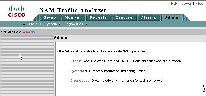
This chapter provides information about performing user and system administration tasks and generating diagnostic information for obtaining technical assistance. The top-level Admin window displays after you click the Admin tab on the NAM GUI. Figure 2-1 shows the top-level Admin window.
Figure 2-1 Top-Level Admin Window
This chapter has the following major sections:
•
User Administration, describes how you configure either a local database or provide information for a TACACS+ database for user authentication and authorization. This section also describes the current user session window.
•
•
User Administration
When you first install the NAM Traffic Analyzer, you use the NAM command-line interface (CLI) to enable the HTTP server and establish a username and password to access the NAM for the first time.
After setting up the initial user accounts, you can create additional accounts, enabling or disabling different levels of access independently for each user. You do this by assigning privileges that correspond to tasks each user can perform, such as configuring RMON collections, configuring system parameters, viewing RMON data, and so on.
Table 2-1 provides information about User Privileges and describes each privilege.
For additional information about creating and editing users, see Creating a New User and Editing a User.
Recovering Passwords
You can recover passwords by using CLI commands on the switch or router. A user with appropriate privileges can reset the NAM CLI and passwords to the factory default state.
For information on resetting the NAM passwords on 6500 Series NAMs, see Catalyst 6500 Series Switch and Cisco 7600 Series Internet Router Network Analysis Module Installation and Configuration Note:
For information on resetting the NAM passwords on NM-NAM devices, see the Network Analysis Module (NM-NAM) feature module.
http://www.cisco.com/en/US/docs/ios/12_3/12_3x/12_3xd/feature/guide/nm_nam.html#
wp1060820For information on resetting the NAM passwords on NME-NAM devices, see the Network Analysis Module (NME-NAM) Installation and Configuration Note.
For information on resetting the NAM passwords on a Cisco NAM 2200 Series Appliance, see the Installation and Configuration Guide for the NAM 2204 Appliance or the Installation and Configuration Guide for the NAM 2220 Appliance
If you have forgotten NAM Traffic Analyzer administrator password, you can recover it using one of these methods:
•
•
Changing Predefined NAM User Accounts on the Switch or Router
The predefined root and guest NAM user accounts (accessible through either a switch or router session command or a Telnet login to the NAM CLI) are static and independent of the NAM Traffic Analyzer. You cannot change these static accounts nor can you add other CLI-based users with the NAM Traffic Analyzer.
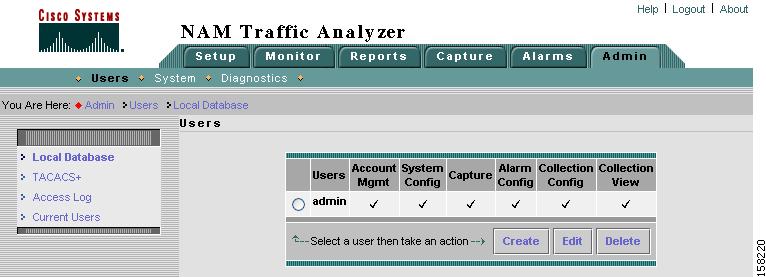
User Administration GUI
The User Administration GUI enables you to manage users. Figure 2-2 shows the top-level User Admin GUI window.
Figure 2-2 User Admin GUI
Creating a New User
To create a new user:
Step 1
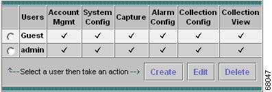
The GUI displays the users in the local database, as shown in Figure 2-3. Checks indicate the privileges each user has for the functions listed.
Figure 2-3 Users Table
Step 2
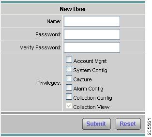
The GUI displays the New User Dialog Box (Figure 2-4).
Figure 2-4 New User Dialog Box
Step 3
Usernames and passwords cannot exceed 32 characters, can be alphanumeric, and can contain special characters except the following:
•
•
•
•
•
•
Step 4
Editing a User
To edit a user's configuration:
Step 1
The Users table displays.
Step 2
Step 3
Step 4
Click Submit to save your changes, or click Reset to clear the dialog of any characters you entered and restore the previous settings.
Deleting a User
To delete a user:
Step 1
The Users table displays.
Step 2
Step 3
Note
Establishing TACACS+ Authentication and Authorization
Terminal Access Controller Access Control System (TACACS) is an authentication protocol that provides remote access authentication, authorization, and related services such as event logging. With TACACS, user passwords and privileges are administered in a central database instead of an individual switch or router to provide scalability.
TACACS+ is a Cisco Systems enhancement that provides additional support for authentication and authorization.
When a user logs into the NAM Traffic Analyzer, TACACS+ determines if the username and password are valid and what the access privileges are.
To establish TACACS+ authentication and authorization:
Step 1
Step 2
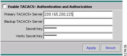
The TACACS+ Authentication and Authorization Dialog Box (Figure 2-5) displays.
Figure 2-5 TACACS+ Authentication and Authorization Dialog Box
Step 3
Step 4
•
•
Tip
Configuring a TACACS+ Server to Support NAM Authentication and Authorization
In addition to enabling the TACACS+ option from the Admin tab, you must configure your TACACS+ server so that it can authenticate and authorize NAM Traffic Analyzer users.
Note
Configuring a Cisco ACS TACACS+ Server
For Windows NT and 2000 Systems
To configure a Cisco ACS TACACS+ server:
Step 1
Step 2
Step 3
Step 4
Step 5
Note
Step 6
Step 7
Adding a NAM User or User Group
To add a NAM user or user group:
Step 1
Step 2
Step 3
Step 4
Step 5
Step 6
Step 7
Step 8
a.
b.
c.
d.
e.
f.
permit capture
permit system
permit collection
permit account
permit alarm
permit view
Step 9
Configuring a Generic TACACS+ Server
To configure a generic TACACS+ server:
Step 1
Step 2
Note
Step 3
service
cmd
cmd-arg
One or more the following:
accountmgmt
system
capture
alarm
collection
view
password authentication method—Password Authentication Protocol (PAP)
Viewing the Current User Sessions Table
The Current User Sessions table is a record of the users who are logged into the application. The user session times out after 30 minutes of inactivity. After a user session times out, that row is removed from the table.
To view the current user sessions table:
Step 1
Step 2
The Current User Sessions Table (Table 2-4) displays.
System Administration
The System option of the Admin tab provides access to the following functions:
•
•
System Resources
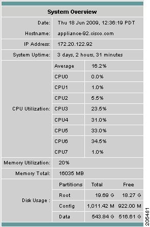
Choose Admin > System to view the System Overview window as shown in Figure 2-6.
Figure 2-6 System Overview Window
Table 2-5 describes the fields of the System Overview window for a NAM with multiple CPUs such as the Cisco NAM 2220 appliance.
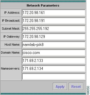
Setting and Viewing Network Parameters
To view and set network parameters:
Step 1
Step 2
The Network Parameters Dialog Box (Figure 2-7) displays.
Figure 2-7 Network Parameters Dialog Box
Step 3
Note
Step 4
•
•
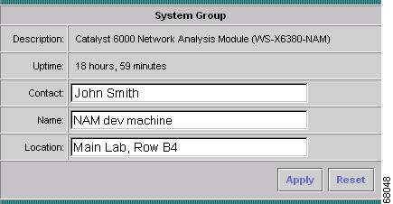
Setting and Viewing the NAM SNMP System Group
To view and set the NAM SNMP system group:
Step 1
Step 2
At the top of the window, the SNMP System Group Dialog Box (Figure 2-8) and NAM Community Strings Dialog Box (Figure 2-9) are displays.
Figure 2-8 SNMP System Group Dialog Box
Step 3
Step 4
•
•
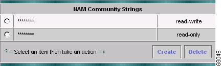
Working with NAM Community Strings
You use community strings so that other applications can send SNMP get and set requests to the NAM, set up collections, poll data, and so on.
Creating NAM Community Strings
To create the NAM community strings:
Step 1
Step 2
At the bottom of the window, the NAM Community Strings Dialog Box displays (Figure 2-9).
Figure 2-9 NAM Community Strings Dialog Box
Step 3
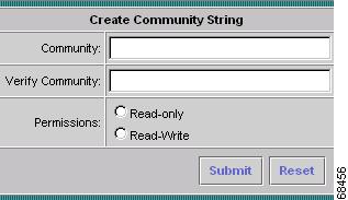
The Create Community String Dialog Box (Figure 2-10) displays.
Figure 2-10 Create Community String Dialog Box
Step 4
Step 5
Step 6
•
•
Step 7
•
•
Deleting NAM Community Strings
To delete the NAM community strings:
Step 1
Step 2
At the bottom of the window, the NAM Community Strings Dialog Box (Figure 2-9) displays.
Step 3
Caution
The community string is deleted.
NAM System Time
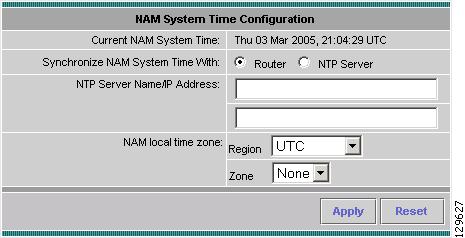
The NAM gets the UTC (GMT) time from one of two sources, depending on its the NAM type. All NAMs can be set up to get their time from an external NTP server. Following is the second option per NAM type:
•
•
•
After the NAM acquires the time, you can set the local time zone using the NAM System Time configuration screen. Figure 2-11 shows the NAM System Time Configuration Screen for NAM-1, NAM-2, and NME-NAMs. You can configure the NAM system time by using one of the following methods:
•
This option is valid only for NAM-1, NAM-2, and NME-NAMs.
•
This option is valid only for Cisco NAM 2200 Series appliances.
•
Figure 2-11 NAM System Time Configuration Screen for NAM-1, NAM-2, and NME-NAMs
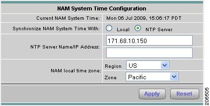
Figure 2-12 shows the Cisco NAM 2200 Series Appliance System Time Configuration Screen.
Figure 2-12 Cisco NAM 2200 Series Appliance System Time Configuration Screen
Synchronizing the NAM System Time with the Switch or Router
Note
To configure the NAM system time from the switch or router:
Step 1
Step 2
Step 3
•
•
Synchronizing the NAM System Time Locally
Note
To configure the NAM system time locally using the NAM appliance command line:
Step 1
Step 2
clock set <hh:mm:ss:> <mm/dd/yyyy>
Step 3
Step 4
Step 5
Step 6
Step 7
•
•
Configuring the NAM System Time with an NTP Server
To configure the NAM system time with an NTP server:
Step 1
Step 2
Step 3
Step 4
Step 5
Step 6
•
•
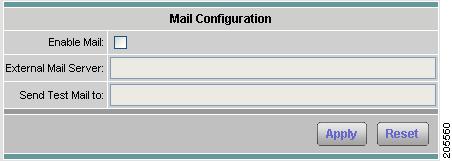
E-Mail Configuration
You can configure the NAM to provide E-Mail notification of alarms and to E-Mail reports. Figure 2-13 shows the Mail Configuration Window. For information about how to configure a report to send using E-Mail, see Table 5-18, Scheduled Exports Window Options, in section Scheduled Exports, page 5-28.
Figure 2-13 Mail Configuration Window
The following procedure describes how to configure the NAM for E-Mail notifications.
Step 1
Step 2
The Mail Configuration Window (Figure 2-13) displays. Table 2-8 describes the Mail Configuration Options.
Step 3
Step 4
Step 5
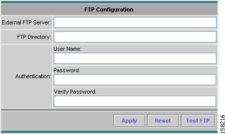
FTP Configuration
You can configure the NAM to provide FTP notification of alarms and to EMail reports. Figure 2-14 shows the FTP Configuration Window. For information about how to configure a report to be transferred using FTP, see Table 5-18, Scheduled Exports Window Options, in section Scheduled Exports, page 5-28.
Figure 2-14 FTP Configuration Window
Table 2-9 describes the fields used for FTP configuration.
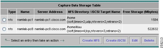
Capture Data Storage
Use the Capture Data Storage option to set up remote file systems to store capture data. You must set up the capture data storage locations prior to setting up data captures. Choose Admin > Capture Data Storage to open the Capture Data Storage window (shown in Figure 2-15).
Figure 2-15 Capture Data Storage Window
This section provides the following:
•
•
•
•
Creating NFS Storage Locations
The NFS server must be configured properly to allow NAM to write data to it. The NAM accesses the NFS directories with UID=80 (www) and UID=0 (root). The NFS directories must be fully accessible by these UIDs.
One way to do this is to use the NFS option all_squash to map these UIDs to anonuid=<userID>, where < userID> is a local user ID with full access rights to the NFS directories.
Configuring the NFS Server
The following example shows how to set up an NFS directory (/home/SomeUserName) in a Linux server for a NAM (at IP address 1.1.1.2) to store capture data. To setup an NFS server directory to store capture data:
Step 1
For example, if the target NFS directory is /home/SomeUserName, open the /etc/password file and search for a user entry that contains something like the following:
SomeUserName:x:503:503::/home/SomeUserName:/bin/tcshIn this example, the UID is 503.
Step 2
/home/SomeUserName 1.1.1.2/255.255.255.255(rw,all_squash,anonuid=503)Step 3
/usr/bin/exportfs -a
Note
Configuring the NFS Storage Location on the NAM
The following procedure describes how to create an NFS storage location by specifying a remote file system partition.
Step 1
The Capture Data Storage window (Figure 2-15) displays and lists any capture data storage locations already configured.
Step 2
Step 3
Table 2-10 describes the NFS Storage location parameters.
Step 4
Editing NFS Storage Locations
The following procedure describes how to edit an existing NFS storage location.
Note
Step 1
The Capture Data Storage window (Figure 2-15) displays and lists any capture data storage locations already configured.
Step 2
The Edit Remote Storage Entry window displays the parameters of the select NFS storage location.
Step 3
Table 2-10 describes the NFS Storage location parameters.
Step 4
Creating iSCSI Storage Locations
The following procedure describes how to create an iSCSI storage location for storing NAM capture data.
Step 1
The Capture Data Storage window (Figure 2-15) displays and lists any capture data storage locations already configured.
Step 2
Step 3
Table 2-11 describes the iSCSI Storage location parameters.
Step 4
Note
Editing iSCSI Storage Locations
The following procedure describes how to edit an existing NFS storage location.
Note
Step 1
The Capture Data Storage window (Figure 2-15) displays and lists any capture data storage locations already configured.
Step 2
The selected iSCSI storage location parameters window displays
Step 3
Table 2-11 describes the iSCSI storage location parameters.
Step 4
Note
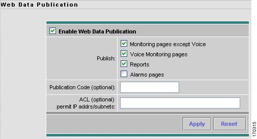
Web Publication
Web publication allows general web users and web sites to access (or link to) selected NAM monitor and report screens without a login session.
Web publication can be open or restricted using Access Control List (ACL) and/or publication code. The publication code, if required, must be present in the URL address or cookie to enable access to published data. Figure 2-16 shows the Web Data Publication Window.
Figure 2-16 Web Data Publication Window
To enable web publishing:
Step 1
Step 2
Step 3
Table 2-12, Web Data Publication Properties, describes the fields of the Enable Web Publishing window.
Step 4
Response Time Export
You can enable response time data export to an external reporting console such as NetQoS SuperAgent. This window works in conjunction with the Setup > Data Sources > WAAS--Devices > Add/Config window. After you enable Response Time Export there, the Export Passthru to External Console option appears on the Add/Config WAAS Device window.
To enable the NAM to export response time data to an external console:
Step 1
The Export window displays.
Step 2
Step 3
Step 4
Step 5
This enables the export of SPAN and other data as well as WAAS traffic.
Step 6
Diagnostics
The Diagnostics option of the Admin tab provides tools to aid in troubleshooting. You can use these tools when you have a problem that might require assistance from the Cisco Technical Assistance Center (TAC). There are options for:
•
Viewing System Alerts
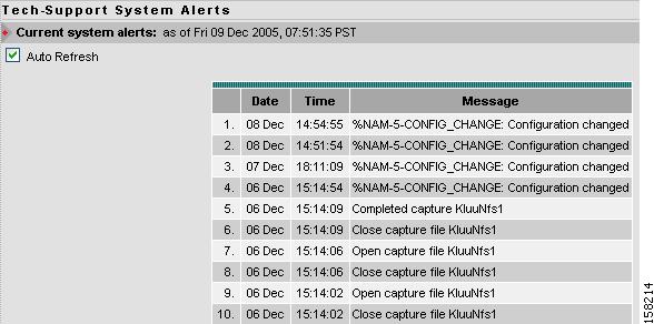
You can view any failures or problems that the NAM Traffic Analyzer has detected during normal operations. To view System Alerts, choose Admin > Diagnostics. System Alerts is the default window. Figure 2-17 shows the System Alerts Window.
Figure 2-17 System Alerts Window
Each alert includes a date, the time the alert occurred, and a message describing the alert. The NAM displays up to one thousand (1,000) of the most-recent alerts. If more than 1,000 alerts have occurred, you need to use the NAM CLI command show tech support to see all of the alerts.
If you notice an alert condition and troubleshoot and attempt to solve the condition causing the alert, you might want to click Clear to remove the list of alerts to see if additional alerts occur.
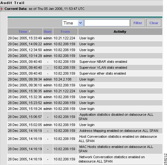
Viewing the Audit Trail
The Audit Trail option displays a listing of recent critical activities that have been recorded in an internal syslog log file. Syslog messages can also be sent to an external log.
The following user activities are logged in the audit trail:
•
•
•
•
•
•
•
•
•
Each log entry will contain the following:
•
•
•
•
To access the audit trail window:
Step 1
Step 2
The Audit Trail Window (Figure 2-18) displays.
The Audit Trail window provides a way to view the user access log and filter entries based on time, user, (IP address) from or activity. The internal log files are rotated after reaching certain size limit.
Figure 2-18 Audit Trail Window
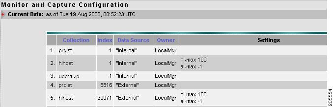
Monitor and Capture Configuration Information
The Monitor and Capture Configuration window contains information about NAM data collections configured by NAM Traffic Analyzer and other management applications. To view the Monitoring and Capturing Configuration information window:
Step 1
Step 2
The NAM displays the Monitor and Capture Configuration Window (Figure 2-19). Each line in the Monitor and Capture Configuration window represents an internal configuration statement for NAM collections, captures, filters, data sources, and alarms. Your configuration might have dozens of statements like these.
Note
Figure 2-19 Monitor and Capture Configuration Window
Step 3
Step 4
If the name LocalMgr is displayed in the Owner column, the collection was configured by the NAM Traffic Analyzer.
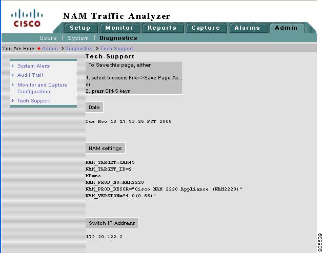
Viewing Technical Support
The NAM syslog records NAM system alerts that contain event descriptions and date and timestamps, indicating unexpected or potentially noteworthy conditions. This feature generates a potentially extensive display of the results of various internal system troubleshooting commands and system logs.
This information is unlikely to be meaningful to the average user. It is intended to be used by the Cisco TAC for debugging purposes. You are not expected to understand this information; instead, you should save the information and attach it to an email message to the Cisco TAC.
Before you can view the Tech-Support page, you must enable the System Config user privilege on the Admin > Users page. For more information on editing user privileges, see the "Editing a User" section.
Note
To view tech support:
Step 1
Step 2
After a few minutes, extensive diagnostic information is generated and displayed in the Diagnostics Tech Support Window (Figure 2-20).
Figure 2-20 Diagnostics Tech Support Window
Step 3
If you are using Internet Explorer, you can click the Save This Page button at the top of the page to download the Tech-Support page as a text file.
Step 4
Downloading Core Files
To download core files from the Tech-Support page, scroll down to the Core Files section and click on the filename.