-
Cisco IP Solution Center API Programmer Guide, 4.0
-
Index
-
About This Guide
-
Introduction to the ISC API
-
Getting Started
-
Common APIs
-
Using Templates
-
Monitoring APIs
-
MPLS Provisioning
-
L2VPN Provisioning
-
VPLS Provisioning
-
QoS Provisioning
-
IPsec Provisioning
-
NAT Provisioning
-
Firewall Provisioning
-
GUI to API Mapping
-
Implementing a Notification Server
-
Scripts
-
 Feedback
Table Of Contents
Provisioning Example for IP QoS
Mark Device Interfaces for QoS
Creating a Network Object for Traffic Classification
Creating the IP QoS Link Profile
Creating an IP QoS Service Request
Provisioning QoS for Existing Services
Provisioning QoS from an MPLS VPN Service Request
QoS Provisioning
Cisco IP Solution Center (ISC) supports quality of service (QoS) provisioning at the access circuit (CPE-to-PE link). ISC can provision QoS policies for a network independent of VPN services (IP QoS), or in addition to VPN services that have been provisioned by ISC.
Standard IP QoS is applied using service level and link level policies and is independent of VPN services. IP QoS provisioning is described in the "Provisioning Example for IP QoS" section.
QoS policies for VPN services are deployed on top of an existing VPN service request, such as MPLS VPN and L2VPN. ISC derives interface configuration information from the VPN service and applies the QoS policy to the interfaces. This type of QoS provisioning is described in the "Provisioning QoS for Existing Services" section.
This chapter describes QoS service concepts and the steps required to provision QoS services using the ISC API. The provisioning example includes the process flow from creating the inventory to auditing the service deployment.
For more information on QoS provisioning using ISC, refer to the Cisco IP Solution Center Integrated VPN Management Suite Quality of Service User Guide, 4.0.
This chapter contains the following sections:
•
Provisioning Example for IP QoS
•
QoS Service Definitions
A QoS service definition specifies the QoS policy, which includes the service class policy and the QoS link profile. Policy attributes and service class attributes are defined in the IPQoS service definition details. The link profile is defined in the Link service definition details (or EoMplsLink for an L2VPN service request).
The QoS service definition can be a QoS, Link, or EoMplsLink policy subtype.
•
•
•
QoS Policy
The QoS policy consists of policy attributes and service class attributes.
•
•
QoS Attributes
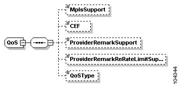
Figure 9-1 shows the schema diagram for QoS policy attributes.
Figure 9-1 QoS Policy Schema Diagram
ISC supports the following properties for QoS:
•
•
•
•
•
Service Class Attributes
The service level QoS policy is the set of rules or conditions that apply to packets as they come across each device interface that has been assigned as a QoS link endpoint. This set of rules is defined in a QoS service class.
A QoS service class can include:
•
•
•
•
•
•
Most networks require at least one service class for interactive voice traffic, one for management traffic, and at least one service class for data traffic. ISC supports the following service class subtypes:
•
•
•
•
•
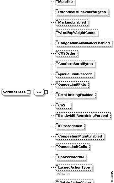
The properties for each service class in the QoS policy are defined in the service definition details. Figure 9-2 shows a partial schema diagram for a QoS policy service class.
Figure 9-2 Service Class Schema Diagram
The following XML example shows a partial list of the properties that can be specified for a service class with Type=DATA:
Tip
<objectPath xsi:type="ns1:CIMObjectPath"><className xsi:type="xsd:string">ServiceClass</className><properties xsi:type="ns1:CIMPropertyList"soapenc:arrayType="ns1:CIMProperty[]"><item xsi:type="ns1:CIMProperty"><name xsi:type="xsd:string">Name</name><value xsi:type="xsd:string">Service1A</value></item><item xsi:type="ns1:CIMProperty"><name xsi:type="xsd:string">Type</name><value xsi:type="xsd:string">DATA</value></item><item xsi:type="ns1:CIMProperty"><name xsi:type="xsd:string">ConformAction</name><value xsi:type="xsd:string">transmit</value><qualifier xsi:type="ns1:CIMQualifier"><name xsi:type="xsd:string">value</name><value xsi:type="xsd:string">2</value></qualifier></item><item xsi:type="ns1:CIMProperty"><name xsi:type="xsd:string">ExceedAction</name><value xsi:type="xsd:string">drop</value><qualifier xsi:type="ns1:CIMQualifier"><name xsi:type="xsd:string">value</name><value xsi:type="xsd:string">1</value></qualifier></item><item xsi:type="ns1:CIMProperty"><name xsi:type="xsd:string">ViolateAction</name><value xsi:type="xsd:string">set-prec-transmit</value><qualifier xsi:type="ns1:CIMQualifier"><name xsi:type="xsd:string">value</name><value xsi:type="xsd:string">3</value></qualifier></item><item xsi:type="ns1:CIMProperty"><name xsi:type="xsd:string">MarkingEnabled</name><value xsi:type="xsd:string">TRUE</value></item><item xsi:type="ns1:CIMProperty"><name xsi:type="xsd:string">DSCP</name><value xsi:type="xsd:string">ef</value></item><item xsi:type="ns1:CIMProperty"><name xsi:type="xsd:string">ShapingEnabled</name><value xsi:type="xsd:string">TRUE</value></item><item xsi:type="ns1:CIMProperty"><name xsi:type="xsd:string">BpsShapingRate</name><value xsi:type="xsd:string">100000000</value></item><item xsi:type="ns1:CIMProperty"><name xsi:type="xsd:string">CongestionMgmtEnabled</name><value xsi:type="xsd:string">TRUE</value></item><item xsi:type="ns1:CIMProperty"><name xsi:type="xsd:string">BandwidthPercent</name><value xsi:type="xsd:string">15</value></item>Link Policy
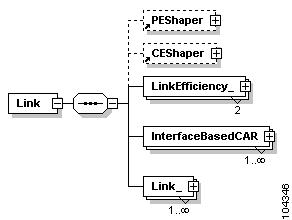
The Link portion of a QoS service definition (called the link profile) defines policy attributes specific to the CPE-to-PE links.
•
•
Figure 9-3 shows the schema diagram for an IP QoS link profile.
Figure 9-3 QoS Link Profile Schema Diagram
IP QoS link profile attributes include:
•
•
•
•
Note
QoS Service Requests
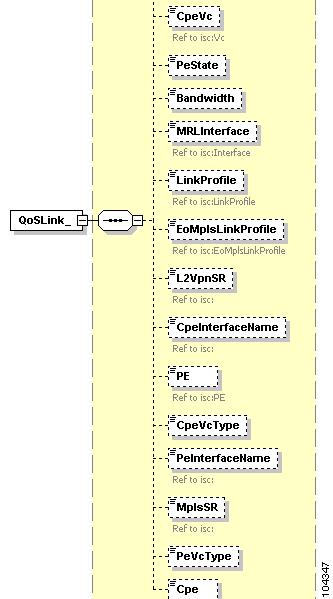
A QoS service request contains the service definition, which includes the QoS link profile and the QoS policy, and the QoSLink properties. The QoSLink properties specify the link endpoint devices, the link bandwidth, and link policy attributes (see Figure 9-4).
Figure 9-4 QoS Service Request Schema Diagram
The following properties are specified with the QoSLink object:
•
–
–
•
–
–
ISC supports three methods for creating QoS service requests:
•
•
•
IP QoS is described in the following provisioning example. Refer to the "Provisioning QoS for Existing Services" section for information on QoS for VPN services.
Provisioning Example for IP QoS
This section describes the required steps for using the API to provision IP QoS and includes the operation, className, and required parameters for each step.
Prequisites
Note
Process Summary
This QoS provisioning example includes the following steps:
•
•
•
•
•
•
•
Provisioning Process
This section provides an example provisioning process using QoS XML examples. The inventory of XML examples for the ISC API can be found at the following location: http://www.cisco.com/univercd/cc/td/doc/product/rtrmgmt/isc/4_0/api/apiref/examples/index.htm
Create Inventory
Every network element that ISC manages must be defined as a device in the system. An element is any device from which ISC can collect configuration information.
Step 1
In most cases, devices are Cisco IOS routers and Catalyst switches.
Table 9-1 Create Devices
createInstance
•
•
One or more of the following:
•
•
•
XML Example:
•
Step 2
The provider is the administrative domain of an Internet service provider (ISP), with one border gateway protocol (BGP) autonomous system (AS) number. The network owned by the provider is called the backbone network. If an ISP has two AS numbers, you must define it as two provider administrative domains. Each provider can contain multiple regions.
Table 9-2 Create Provider and Region
createInstance
Provider
•
•
Region
•
•
XML Examples:
•
•
Step 3
Table 9-3 Create PEs
createInstance
PE
•
•
•
–
–
•
•
XML Example:
•
Step 4
Table 9-4 Create Customer and Site
createInstance
Organization
•
Site
•
•
XML Examples:
•
•
Step 5
When you declare a device as a CPE, you also specify a ManagementType and interface information.
Table 9-5 Create CPEs
createInstance
Cpe
•
•
•
XML Example:
•
Collect Device Configurations
A device configuration collection is a task. This task uploads the current configuration from the device to the ISC database. The collection task executed through a service request, and the service request is scheduled through a service order.
The following example is a partial XML request used to collect the configuration from device enqospe1.
<objectPath xsi:type="ns1:CIMObjectPath"><className xsi:type="xsd:string">ServiceRequestDetails</className><properties xsi:type="ns1:CIMPropertyList"soapenc:arrayType="ns1:CIMProperty[]"><item xsi:type="ns1:CIMProperty"><name xsi:type="xsd:string">SubType</name><value xsi:type="xsd:string">COLLECTION</value></item><item xsi:type="ns1:CIMProperty"><name xsi:type="xsd:string">Device</name><value xsi:type="xsd:string">enqospe1</value></item><item xsi:type="ns1:CIMProperty"><name xsi:type="xsd:string">RetrieveDeviceAttributes</name><value xsi:type="xsd:string">true</value> </item><item xsi:type="ns1:CIMProperty"><name xsi:type="xsd:string">RetrieveDeviceInterfaces</name><value xsi:type="xsd:string">true</value> </item></properties></objectPath>XML Example:
•
Mark Device Interfaces for QoS
For QoS provisioning, you must mark both interfaces in the CPE-to-PE link. Typically, the service provider supplies the list of devices and interfaces to be marked for QoS provisioning. CPE devices are generally marked at provider-facing interfaces, and PE devices at customer-facing interfaces.
Create an XML request to modify the device, and mark the interface as a QoS link endpoint.
The following example shows a modifyInstance operation for CPE device enqosce52 and specifies QoSLinkEndpoint=true for interfaceATM1/0.52.
<ns1:modifyInstance><objectPath subAction="modifyInstance" xsi:type="ns1:CIMObjectPath"><className xsi:type="xsd:string">Cpe</className><keyProperties xsi:type="ns1:CIMKeyPropertyList"soapenc:arrayType="ns1:CIMKeyProperty[]"><item xsi:type="ns1:CIMKeyProperty"><name xsi:type="xsd:string">Device</name><value xsi:type="xsd:string">enqosce52</value></item></keyProperties><objectPath subAction="createInstance" xsi:type="ns1:CIMObjectPath"><className xsi:type="xsd:string">Interface</className><properties xsi:type="ns1:CIMPropertyList"soapenc:arrayType="ns1:CIMProperty[]"><item xsi:type="ns1:CIMProperty"><name xsi:type="xsd:string">Name</name><value xsi:type="xsd:string">ATM1/0.52</value></item><item xsi:type="ns1:CIMProperty"><name xsi:type="xsd:string">QoSLinkEndpoint</name><value xsi:type="xsd:string">true</value></item></properties></objectPath></objectPath></ns1:modifyInstance>
XML Examples:
•
•
Creating a Network Object for Traffic Classification
This step is optional.
Create a network object to classify traffic based on network addresses contained in variables, instead of based on protocols. The Name value of the network object is used later in the process, in the traffic classification of a ServiceClass when you define the QoS policy in the service definition.
Table 9-8 Create Network Object
createInstance
NetworkObject
•
•
•
•
See the following example:
<ns1:createInstance><objectPath xsi:type="ns1:CIMObjectPath"><className xsi:type="xsd:string">NetworkObject</className><properties xsi:type="ns1:CIMPropertyList"soapenc:arrayType="ns1:CIMProperty[]"><item xsi:type="ns1:CIMProperty"><name xsi:type="xsd:string">Name</name><value xsi:type="xsd:string">address_1</value></item><item xsi:type="ns1:CIMProperty"><name xsi:type="xsd:string">Cpe</name><value xsi:type="xsd:string">enqosce52</value></item><item xsi:type="ns1:CIMProperty"><name xsi:type="xsd:string">Type</name><value xsi:type="xsd:string">NETWORK</value></item><item xsi:type="ns1:CIMProperty"><name xsi:type="xsd:string">Value</name><value xsi:type="xsd:string">12.12.12.0/24</value></item></properties></objectPath></ns1:createInstance>XML Example:
•
Creating a QoS Policy
A QoS policy is a template of the parameters needed to define a QoS service request. After you define the policy template, it can be used by all QoS service requests that share a common set of attributes.
The QoS Policy consists of:
•
•
This section describes how to set the QoS attributes of an IP QoS service definition. See the "Creating the IP QoS Link Profile" section for information on setting the Link attributes.
To use a variable for traffic classification, include the name of a Network Object variable that has already been created.
In the following XML example, the address_1 variable is called in the TrafficClassification class. This variable was created in the "Creating a Network Object for Traffic Classification" section.
<objectPath xsi:type="ns1:CIMObjectPath"><className xsi:type="xsd:string">TrafficClassification</className><properties xsi:type="ns1:CIMPropertyList"soapenc:arrayType="ns1:CIMProperty[]"><item xsi:type="ns1:CIMProperty"><name xsi:type="xsd:string">FromAddressVariable</name><value xsi:type="xsd:string">address_1</value></item></properties></objectPath>XML Example:
•
Creating the IP QoS Link Profile
This section describes how to set the Link attributes of an IP QoS service definition. See the "Creating a QoS Policy" section for information on setting the QoS attributes.
Note
The IP QoS link profile sets the QoS Link attributes. The Link attributes include:
•
•
•
•
XML Example:
•
Creating an IP QoS Service Request
This section describes how to create a service request for IP QoS. The QoS service request is deployed through a service order. For information on provisioning QoS for an existing L2VPN or MPLS VPN service request, see the "Provisioning QoS for Existing Services" section.
A QoS service request contains the service definition, which includes the QoS link profile and the QoS policy, and the QoSLink properties. The QoSLink properties specify the link endpoint devices, link bandwidth, and link policy attributes.
Note
Tip
XML Example:
•
Auditing Service Requests
A configuration audit occurs automatically each time you deploy a service request. During this configuration audit, ISC verifies that all Cisco IOS commands are present and that they have the correct syntax. An audit also verifies that there were no errors during deployment by examining the commands configured by the service request on the target devices. If the device configuration does not match what is defined in the service request, the audit flags a warning and sets the service request to a Failed Audit or Lost state.
If you do not want the configuration audit to occur, change the value for the Audit parameter. The Audit parameter supports these values:
•
•
•
You can use the Audit parameter with a Create, Modify, or Decommission service request or a Deployment task. See the "Service Decommission" section for more information. To perform a configuration audit as a separate task, see the "Configuration Audit" section.
Provisioning QoS for Existing Services
If your VPN services have been provisioned by ISC, you can add QoS policies to an existing service request. The following QoS attributes can be added to existing VPN services:
•
Note
•
When you provision QoS for an existing service, the preliminary operations of creating inventory, collecting configurations, and marking device endpoints are not required. You provision QoS for VPN services that are already in the deployed state, and the preliminary operations are specified within the existing L2VPN or MPLS VPN service request. During deployment, the QoS service request relies on port/interface configuration from the existing services.
QoS is provisioned with a service order that includes a QoS service definition, which defines the QoS policy and the appropriate link profile, and the L2VPN or MPLS VPN service request. The QoS service request is deployed through the service order.
L2VPN Ethernet QoS Policy
For an L2VPN network, ISC applies QoS rate-limiting parameters to traffic as it leaves the CLE device (the PE device UNI).
To provision QoS for an already deployed L2VPN service request, you need the L2VPN service request locator ID and a service definition with an EoMPLS link profile (Type=EoMplsLink). The EoMPLS link profile includes the committed information rate (CirBps) and the committed burst (BurstBytes).
XML Example:
•
Provisioning QoS from an MPLS VPN Service Request
For an MPLS VPN network, ISC marks packets with an MPLS Exp. value at the PE device ingress interface.
ISC supports the following QoS parameters for MPLS VPNs:
•
•
•
•
XML Example:
•