-
Cisco IP Solution Center API Programmer Guide, 4.0
-
Index
-
About This Guide
-
Introduction to the ISC API
-
Getting Started
-
Common APIs
-
Using Templates
-
Monitoring APIs
-
MPLS Provisioning
-
L2VPN Provisioning
-
VPLS Provisioning
-
QoS Provisioning
-
IPsec Provisioning
-
NAT Provisioning
-
Firewall Provisioning
-
GUI to API Mapping
-
Implementing a Notification Server
-
Scripts
-
 Feedback
Table Of Contents
L2VPN Provisioning
To provision L2VPN using the Cisco IP Solution Center (ISC) API, you need an L2VPN service policy of a specific subtype and an L2VPN service request.
The service policy (defined in a service definition) specifies the attributes common to the end-to-end wires and attachment circuits (ACs).
The service request defines the device interfaces for each end-to-end wire connection (called link endpoints in the GUI), and can optionally override policy attributes in each end-to-end wire link and AC.
When you deploy an L2VPN service request using a service order, the attributes specified in the service definition are applied to the devices and interfaces listed in the service request, along with the attributes for each end-to-end wire link and AC.
This chapter describes L2VPN service concepts and the steps required to provision L2VPN services using the ISC API. The provisioning example includes the process flow from creating the inventory to auditing the service deployment.
For more information on L2VPN provisioning using ISC, refer to the Cisco IP Solution Center Integrated VPN Management Suite L2VPN User Guide, 4.0.
This chapter contains the following sections:
L2VPN Service Definitions
An L2VPN service definition specifies the policy subtype, the properties for the CPE and PE devices, and the user network interface (UNI). The properties that can be set are based on the policy subtype that is specified in the service definition.
ISC supports the following L2VPN service definition subtypes:
•
EthernetEVCS (Ethernet Virtual Circuit Service)
•
•
•
•
•
•
•
Note
A service definition can be shared by one or more service requests that have similar requirements. L2VPN service definitions include the following information about the end-to-end wires and attachment circuits:
•
•
•
•
•
Note
L2VPN Service Requests
An L2VPN service request specifies the service definition, assigns device interfaces for the end-to-end wire connections, and the attachment circuit details.
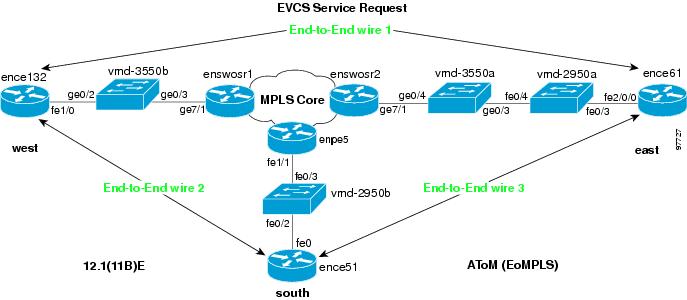
End-To-End Wires
An end-to-end wire is the link from one endpoint through the service provider cloud to another endpoint. In most cases, these links are from CE to CE. An attachment circuit is the link from the CE to the PE. If there is not CE present, the attachment circuit link is from PE-CLE to PE-CLE.
In the EthernetEVCS network example shown in Figure 7-1, End-to-End wire1 is shown from ence132 to ence61. The two attachment circuits are the links from ence132 to enswosr1 and from ence61 to enswosr2.
Figure 7-1 End to End Wire Network Example
The number of end-to-end wires and attachment circuits that can be created are based on the policy subtype.
There can be 1 or 2 AttachmentCircuits for every EndToEndWire for the following policy subtypes:
•
•
•
•
There are 2 AttachmentCircuits for every EndToEndWire for the following policy subtypes:
•
•
•
•
Provisioning Example
This section describes the required steps for using the API to provision L2VPN, and includes the operation, class, and required parameters for each step.
Process Summary
In this L2VPN provisioning example, the following steps are listed:
•
•
•
•
•
•
•
•
•
•
•
•
•
•
•
•
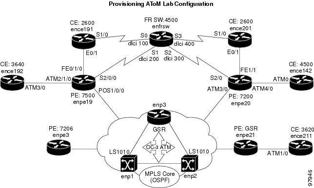
Note
The provisioning example in this section is based on the partial network diagram shown in Figure 7-2.
Figure 7-2 L2VPN Provisioning Network Example
Prerequisites
For security reasons, ISC requires the virtual terminal protocol (VTP) to be configured in transparent mode on all switches involved in Ethernet Relay Service (ERS) or Ethernet Wire Service (EWS) before provisioning L2VPN service requests.
To set the VTP mode, enter the following Cisco IOS commands:
configure terminalvtp mode transparentEnter the following Cisco IOS command to verify that the VTP has changed to transparent mode:
Show vtp statusRBAC
ISC uses a Cisco role-based access control (RBAC) product for user login and logoff. These user roles and permissions are set up using the GUI.
When you establish an API session, you are given a session token during the login. For each API XML request, the session token is verified against the RBAC processor to ensure that the API user has permissions for that operation. If the user does not have permissions, the API returns an error.
Refer to the Cisco IP Solution Center Integrated VPN Management Suite Infrastructure Reference, 4.0 for information on setting up user roles and permissions.
Provisioning Process
This section provides an example provisioning process using XML examples. The inventory of XML examples for the ISC API can be found at the following location: http://www.cisco.com/univercd/cc/td/doc/product/rtrmgmt/isc/4_0/api/apiref/examples/index.htm
Step 1
Table 7-1 Create Device Group
createInstance
DeviceGroup
Name
In this example, one device group is created for the customer, and one for the provider.
•
•
XML Examples:
CreateDeviceGroup.xml
Tip
In the following example, the device group (CustDev) is added as a key property when creating the device CiscoRouter:
<ns1:createInstance><objectPath xsi:type="ns1:CIMObjectPath"><className xsi:type="xsd:string">CiscoRouter</className><properties xsi:type="ns1:CIMPropertyList" soapenc:arrayType="ns1:CIMProperty[]"><item xsi:type="ns1:CIMProperty"><name xsi:type="xsd:string">DeviceGroup</name><value xsi:type="xsd:string">CustDev</value></item><item xsi:type="ns1:CIMProperty"><name xsi:type="xsd:string">CfgUpDnldMech</name><value xsi:type="xsd:string">DEFAULT</value></item><item xsi:type="ns1:CIMProperty"><name xsi:type="xsd:string">TransportMechanism</name><value xsi:type="xsd:string">DEFAULT</value></item><item xsi:type="ns1:CIMProperty"><name xsi:type="xsd:string">Password</name><value xsi:type="xsd:string">vpnsc</value></item>Step 2
Every network element that ISC manages must be defined as a device in the system. An element is any device from which ISC can collect information. In most cases, devices are Cisco IOS routers and Catalyst switches.
Table 7-2 Create Devices
createInstance
•
•
One or more of the following:
•
•
•
In this example, an XML request is created for each device in the CPE to PE link, as shown in Figure 7-2.
•
•
•
•
XML Examples:
•
•
Step 3
A device configuration collection is a task. This task uploads the current configuration from the device to the ISC database. The collection task is executed through a service request, and the service request is scheduled through a service order.
In this example, device collection is divided into two separate tasks. One task performs a configuration collection on the devices in the customer device group, and the second task is for the provider device group. (Device groups were created in Step 1.)
•
•
Note
XML Example:
•
Step 4
The provider is the administrative domain of an ISP, with one BGP autonomous system (AS) number. The network owned by the provider is called the backbone network. If an ISP has two AS numbers, you must define it as two provider administrative domains.
Table 7-4 Create Provider
createInstance
Provider
•
•
XML Example:
•
Step 5
Each provider can contain multiple regions. In this example, an XML request is created for each region.
•
•
XML Example:
•
Step 6
The XML request that assigns a PE role (PE-POP or PE-CLE) to a device is also used to:
•
•
Table 7-6 Create PEs
createInstance
PE
•
•
•
–
–
•
•
In this example, an XML request is created for each device to be declared as a PE. Using Figure 7-2 for reference, enpe21=PE1 and enpe20=PE2.
•
•
XML Example:
•
Step 7
Create an access domain for Ethernet-based services where ISC automatically assigns a VLAN for the link from the VLAN pool. Select all PE-POP devices to be associated with this domain, and later in the process, when VLAN pools are created for an Access Domain, the PE-POP is automatically assigned a VLAN ID.
Table 7-7 Create Access Domains
createInstance
AccessDomain
•
•
•
XML Example:
•
Step 8
A customer is a requestor of VPN services. Each customer can contain multiple customer sites. Each site belongs to only one customer and can contain many CPEs.
XML Examples:
•
Step 9
Create sites and assign customers (Organizations) to them. In this example, an XML request is created for each site.
•
•
Table 7-9 Create Sites
createInstance
Site
•
•
XML Examples:
•
Step 10
The XML request that assigns a CPE to a site is also used to specify:
•
•
Table 7-10 Create CPE Devices
createInstance
Cpe
•
•
•
In this example, an XML request is created for each device you want specified as a CPE. Using the network diagram for reference, ence142=Cpe1 and ence211=Cpe2.
•
•
XML Example:
•
Step 11
Create an NPC for each physical link in the CPE to PE-POP end-to-end wire. If there are intermediate devices, those links must also be added to the NPC using PhysicalLink.
Note
Table 7-11 Create NPCs
createInstance
NamedPhysicalCircut
PhysicalLink
PhysicalLink
•
•
•
•
In this example, create an XML request for each CPE to PE-POP link. Using Figure 7-2 for reference, ence142 to enpe20=NPC1 and from ence211 to enpe21=NPC2.
•
•
Optionally, you can create one XML request for the NamedPhysicalCircuit and include multiple PhysicalLinks as shown in the following example:
<ns1:createInstance><objectPath xsi:type="ns1:CIMObjectPath"><className xsi:type="xsd:string">NamedPhysicalCircuit</className><properties xsi:type="ns1:CIMPropertyList"soapenc:arrayType="ns1:CIMProperty[]"></properties><objectPath xsi:type="ns1:CIMObjectPath"><className xsi:type="xsd:string">PhysicalLink</className><properties xsi:type="ns1:CIMPropertyList"soapenc:arrayType="ns1:CIMProperty[]"><item xsi:type="ns1:CIMProperty"><name xsi:type="xsd:string">SrcDevice</name><value xsi:type="xsd:string">Device1</value> </item><item xsi:type="ns1:CIMProperty"><name xsi:type="xsd:string">DestDevice</name><value xsi:type="xsd:string">Device2</value> </item><item xsi:type="ns1:CIMProperty"><name xsi:type="xsd:string">SrcIfName</name><value xsi:type="xsd:string">Intf1/0</value> </item><item xsi:type="ns1:CIMProperty"><name xsi:type="xsd:string">DestIfName</name><value xsi:type="xsd:string">Intf2/1</value> </item></properties><objectPath xsi:type="ns1:CIMObjectPath"><className xsi:type="xsd:string">PhysicalLink</className><properties xsi:type="ns1:CIMPropertyList"soapenc:arrayType="ns1:CIMProperty[]"><item xsi:type="ns1:CIMProperty"><name xsi:type="xsd:string">SrcDevice</name><value xsi:type="xsd:string">Device3</value> </item><item xsi:type="ns1:CIMProperty"><name xsi:type="xsd:string">DestDevice</name><value xsi:type="xsd:string">Device5</value> </item><item xsi:type="ns1:CIMProperty"><name xsi:type="xsd:string">SrcIfName</name><value xsi:type="xsd:string">Intf3/0</value> </item><item xsi:type="ns1:CIMProperty"><name xsi:type="xsd:string">DestIfName</name><value xsi:type="xsd:string">Intf5/1</value> </item></properties></objectPath></objectPath></ns1:createInstance>XML Examples:
•
•
•
Step 12
Create a VLAN ID pool, specify a range, and associate it to an access domain to manually enter the parameters for a VLAN pool. To have ISC automatically assign VLANs to end-to-end wire links, specify the AutoPickVlanId keyword in the service definition (see Step 15).
Table 7-12 Create VLAN Pool
createInstance
VlanIdPool
•
•
•
•
XML Example:
•
Step 13
Table 7-13 Create VC ID Pool
createInstance
VcIdPool
•
•
XML Example:
•
Step 14
A VPN in an L2VPN network is only a name used to group L2VPN links.
XML Example:
•
Step 15
A service definition is a template of the parameters needed to define an L2VPN service request. Once you define the policy template, it can be used by all L2VPN service requests that share a common set of attributes.
Certain properties in the service definition can set an additional attribute, editable=true. This allows the service request creator to change the values on specific policy attributes. If the property is set to editable=false, the service request creator cannot change the policy attributes. See the following example:
<objectPath xsi:type="ns1:CIMObjectPath"><className xsi:type="xsd:string">ServiceDefinitionDetails</className><properties xsi:type="ns1:CIMPropertyList"soapenc:arrayType="ns1:CIMProperty[]"><item xsi:type="ns1:CIMProperty"><name xsi:type="xsd:string">SubType</name><value xsi:type="xsd:string">ATM</value></item><item xsi:type="ns1:CIMProperty"><name xsi:type="xsd:string">PE_Encap</name><value xsi:type="xsd:string">AAL0</value><qualifier xsi:type="ns1:CIMQualifier"><name xsi:type="xsd:string">editable</name><value xsi:type="xsd:string">true</value></qualifier></item><item xsi:type="ns1:CIMProperty"><name xsi:type="xsd:string">CE_Intf_Type</name><value xsi:type="xsd:string">Switch</value><qualifier xsi:type="ns1:CIMQualifier"><name xsi:type="xsd:string">editable</name><value xsi:type="xsd:string">true</value></qualifier></item>In this example, a service definition is created, with a SubType=ATM, and policy attribute values for the Cpe, PE, and UNI with the ServiceDefinitionDetails.
•
Note
XML Examples:
•
•
•
•
•
•
•
•
Step 16
An L2VPN service request consists of one or more end-to-end wires, connecting various sites in a point-to-point topology. When you create a service request, you enter several parameters, including the service definition to use, the specific interfaces on the CPE (or UNI) and PE devices, routing protocol information, and IP addressing information.
In this example, an L2VPN service request is created for an ATM network with the CE present. The service request is deployed through a service order. The ServiceRequestDetails specify the attributes for the end-to-end wires and attachment circuits.
Table 7-16 Create a Service Request
createInstance
ServiceOrder
•
•
•
ServiceRequest
•
•
•
ServiceRequestDetails
•
–
•
•
EndtoEndWire
•
AttachmentCircuit
•
–
Note
Tip
XML Examples:
•
•
•
•
•
•
•
•
Auditing Service Requests
A configuration audit occurs automatically each time you deploy a service request. During this configuration audit, ISC verifies that all Cisco IOS commands are present and that they have the correct syntax. An audit also verifies that there were no errors during deployment by examining the commands configured by the service request on the target devices. If the device configuration does not match what is defined in the service request, the audit flags a warning and sets the service request to a Failed Audit or Lost state.
If you do not want the configuration audit to occur, change the value for the Audit parameter. The Audit parameter supports these values:
•
•
•
You can use the Audit parameter with a Create, Modify, or Decommission service request or a Deployment task. See the "Service Decommission" section for more information. To perform a configuration audit as a separate task, see the "Configuration Audit" section.