-
Cisco IOS IP Configuration Guide, Release 12.2
-
About Cisco IOS Software Documentation
-
Using Cisco IOS Software
-
IP Overview
- Part 1: IP Addressing Services
- Part 2: IP Routing Protocols
-
Part 3: IP Multicast
-
Configuring IP Multicast Routing
-
Configuring Source Specific Multicast
-
Configuring Bidirectional PIM
-
Configuring Multicast Source Discovery Protocol
-
Configuring PGM Host and Router Assist
-
Configuring Unidirectional Link Routing
-
Using IP Multicast Tools
-
Configuring Router-Port Group Management Protocol
-
Configuring DVMRP Interoperability
-
-
 Feedback
Table Of Contents
Configuring Unidirectional Link Routing
UDLR Tunnel Configuration Task List
IGMP UDLR Configuration Task List
Changing the Distance for the Default RPF Interface
IGMP Proxy Configuration Task List
Integrated UDLR Tunnel, IGMP UDLR, and IGMP Proxy Example
Configuring Unidirectional Link Routing
This chapter describes the unidirectional link routing (UDLR) feature. UDLR provides mechanisms for a router to emulate a bidirectional link to enable the routing of unicast and multicast packets over a physical unidirectional interface, such as a broadcast satellite link. However, there must be a back channel or other path between the routers that share a physical unidirectional link (UDL). A UDLR tunnel is a mechanism for unicast and multicast traffic; Internet Group Management Protocol (IGMP) UDLR and IGMP Proxy are mechanisms for multicast traffic.
For information about tunnel interfaces, refer to the "Configuring Logical Interfaces" chapter in the Cisco IOS Interface Configuration Guide. For information about IGMP, refer to the chapter "Configuring IP Multicast Routing" in the Cisco IOS IP Configuration Guide.
For a complete description of the UDLR commands used in this chapter, refer to the "Unidirectional Link Routing Commands" chapter in the Cisco IOS IP Command Reference, Volume 3 of 3: Multicast. To locate documentation of other commands that appear in this chapter, use the command reference master index, or search online.
To identify the hardware platform or software image information associated with a feature, use the Feature Navigator on Cisco.com to search for information about the feature or refer to the software release notes for a specific release. For more information, see the "Identifying Supported Platforms" section in the "Using Cisco IOS Software" chapter.
UDLR Overview
Both unicast and multicast routing protocols forward data on interfaces from which they have received routing control information. This model works only on bidirectional links for most existing routing protocols. However, some networks use broadcast satellite links, which are unidirectional. For networks that use broadcast satellite links, accomplishing two-way communication over broadcast satellite links presents a problem in terms of discovering and sharing knowledge of a network topology.
Specifically, in unicast routing, when a router receives an update message on an interface for a prefix, it forwards data for destinations that match that prefix out that same interface. This is the case in distance vector routing protocols. Similarly, in multicast routing, when a router receives a join message for a multicast group on an interface, it forwards copies of data destined for that group out that same interface. Based on these principles, existing unicast and multicast routing protocols cannot be supported over UDLs. UDLR is designed to enable the operation of routing protocols over UDLs without changing the routing protocols themselves.
UDLR enables a router to emulate the behavior of a bidirectional link for IP operations over UDLs. UDLR has three complementary mechanisms for bidirectional link emulation, which are described in the following sections:
•
UDLR Tunnel
•
•
You can use each mechanism independently or in conjunction with the others.
UDLR Tunnel
The UDLR tunnel mechanism enables IP and its associated unicast and multicast routing protocols to treat the UDL as being logically bidirectional. A packet that is destined on a receive-only interface is picked up by the UDLR tunnel mechanism and sent to an upstream router using a generic routing encapsulation (GRE) tunnel. The control traffic flows in the opposite direction as the user data flow. When the upstream router receives this packet, the UDLR tunnel mechanism makes it appear that the packet was received on a send-only interface on the UDL.
The purpose of the unidirectional GRE tunnel is to move control packets from a downstream node to an upstream node. The one-way tunnel is mapped to a one-way interface (that goes in the opposite direction). Mapping is performed at the link layer, so the one-way interface appears bidirectional. When the upstream node receives packets over the tunnel, it must make the upper-layer protocols act as if the packets were received on the send-capable UDL.
UDLR tunnel supports the following features:
•
•
•
Note
IGMP UDLR
Another mechanism that enables support of multicast routing protocols over UDLs is using IP multicast routing with IGMP, which has been enhanced to accommodate UDLR. This mechanism scales well for many broadcast satellite links.
With IGMP UDLR, an upstream router sends periodic queries for members on the UDL. The queries include a unicast address of the router that is not the unicast address of the unidirectional interface. The downstream routers forward IGMP reports received from directly connected members (on interfaces configured to helper forward IGMP reports) to the upstream router. The upstream router adds the unidirectional interface to the (*, G) outgoing interface list, thereby enabling multicast packets to be forwarded down the UDL.
In a large enterprise network, it is not possible to be able to receive IP multicast traffic via satellite and forward the traffic throughout the network. This limitation exists because receiving hosts must be directly connected to the downstream router. However, you can use the IGMP Proxy mechanism to overcome this limitation. See the "IGMP Proxy" section later in this chapter for more information on this mechanism.
For information on IGMP, refer to the "Configuring IP Multicast Routing" chapter in the Cisco IOS IP Configuration Guide.
IGMP Proxy
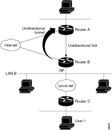
The IGMP Proxy mechanism enables hosts that are not directly connected to a downstream router to join a multicast group sourced from an upstream network. Figure 82 illustrates this mechanism.
Figure 82 IGMP Mroute Proxy Mechanism
In the scenario in Figure 82, the following sequence of events occurs:
1.
2.
3.
4.
5.
In an enterprise network, for example, it is desirable to be able to receive IP multicast traffic via satellite and forward the traffic throughout the network. With IGMP UDLR alone, this scenario is not possible because receiving hosts must be directly connected to the downstream router. IGMP Proxy overcomes this limitation by creating an IGMP report for (*, G) entries in the multicast forwarding table. To make this scenario functional, you must configure PIM sparse mode (PIM-SM) in the network, make the UDL downstream router the rendezvous point (RP) for a select set of addresses, and configure mroute proxy on interfaces leading to PIM-enabled networks with potential members. When the UDL downstream router has a (*, G) forwarding entry for an mroute proxy interface, an IGMP report for the group is created and sent to a loopback interface (IGMP Proxy interface). The loopback interface then uses the same mechanism as IGMP UDLR to forward reports upstream.
Note
UDLR Tunnel Configuration Task List
To configure a UDLR tunnel, perform the required tasks described in the following section:
•
Prerequisite
Before configuring UDLR tunnel, ensure that all routers on the UDL have the same subnet address. If all routers on the UDL cannot have the same subnet address, the upstream router must be configured with secondary addresses to match all the subnets that the downstream routers are attached to.
Configuring UDLR Tunnel
When configuring a UDLR tunnel, you must configure both the upstream and downstream routers to meet the following conditions:
•
•
•
•
•
To configure a UDLR tunnel on the upstream router, use the following commands beginning in global configuration mode:
To configure a UDLR tunnel on the downstream router, use the following commands beginning in global configuration mode:
See the "UDLR Tunnel Example" section later in this chapter for an example of how to configure a UDLR tunnel. See the "Integrated UDLR Tunnel, IGMP UDLR, and IGMP Proxy Example" section later in this chapter for an example of how to set up all three UDLR mechanisms in the same configuration.
IGMP UDLR Configuration Task List
To configure IGMP UDLR, perform the tasks described in the following sections. The tasks in the first section are required; the tasks in the remaining sections are optional.
•
•
•
Prerequisites
Before configuring IGMP UDLR, ensure that the following conditions exist:
•
•
Configuring the IGMP UDL
To configure an IGMP UDL, you must configure both the upstream and downstream routers to meet the following conditions:
•
•
To configure the IGMP UDL on the upstream router, use the following command in interface configuration mode:
Router(config-if)# ip igmp unidirectional-link
Configures IGMP on the interface to be unidirectional.
To configure the IGMP UDL on the downstream router, use the following commands in interface configuration mode:
See the "IGMP UDLR Example" section later in this chapter for an example of how to configure IGMP UDLR. See the "Integrated UDLR Tunnel, IGMP UDLR, and IGMP Proxy Example" section later in this chapter for an example of how to set up all three UDLR mechanisms in the same configuration.
Changing the Distance for the Default RPF Interface
By default, the distance for the default Reverse Path Forwarding (RPF) interface is 15. Any explicit sources learned by routing protocols will take preference if their distance is less than the distance configured by the ip multicast default-rpf-distance global configuration command.
If you want IGMP to prefer the UDLR link, set the distance to be less than the distances of the unicast routing protocols. If you want IGMP to prefer the non-UDLR link, set the distance to be greater than the distances of the unicast routing protocols. This task might be required on downstream routers if you want some sources to use RPF to reach the UDLR link and others to use the terrestrial paths.
To change the distance for the default RPF interface, use the following command in global configuration mode:
Router(config)# ip multicast default-rpf-distance distance
Changes the distance for the default RPF interface.
Monitoring IGMP UDLR
To display UDLR information for directly connected groups on interfaces that have a UDL helper address configured, use the following command in EXEC mode:
IGMP Proxy Configuration Task List
To configure IGMP Proxy, perform the tasks described in the following sections. The tasks in the first section are required; the tasks in the remaining section are optional.
•
•
Prerequisites
Before configuring IGMP Proxy, ensure that the following conditions exist:
•
•
Configuring IGMP Proxy
To configure IGMP Proxy, use the following commands in interface configuration mode:
See the "IGMP Proxy Example" section later in this chapter for an example of how to configure IGMP Proxy. See the "Integrated UDLR Tunnel, IGMP UDLR, and IGMP Proxy Example" section later in this chapter for an example of how to set up all three UDLR mechanisms in the same configuration.
Verifying IGMP Proxy
To verify that IGMP Proxy is configured properly, use the show ip igmp interface EXEC command. The following sample output shows that IGMP Proxy is configured on Ethernet interface 1/0/6.
router# show ip igmp udlrIGMP UDLR Status, UDL Interfaces:Ethernet1/0/6Group Address Interface UDL Reporter Reporter Expires239.1.1.2 Ethernet1/0/6 10.10.0.3 00:02:59239.1.1.1 Ethernet1/0/6 10.10.0.2 00:02:40UDLR Configuration Examples
This section provides the following UDLR examples:
•
UDLR Tunnel Example
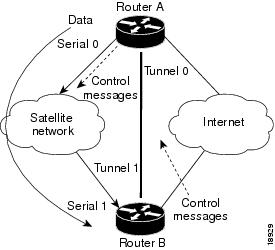
The following example shows how to configure a UDLR tunnel. In the example, Router A (the upstream router) is configured with Open Shortest Path First (OSPF) and PIM. Serial interface 0 has send-only capability. Therefore, the UDLR tunnel is configured as receive only, and points to serial 0.
Router B (the downstream router) is configured with OSPF and PIM. Serial interface 1 has receive-only capability. Therefore, the UDLR tunnel is configured as send-only, and points to serial 1. The forwarding of ARP and NHRP is enabled. Figure 83 illustrates the example.
Figure 83 UDLR Tunnel Example
Router A Configuration
ip multicast-routing!! Serial0 has send-only capability!interface serial 0encapsulation hdlcip address 10.1.0.1 255.255.0.0ip pim sparse-dense-mode!! Configure tunnel as receive-only UDLR tunnel.!interface tunnel 0tunnel source 11.0.0.1tunnel destination 11.0.0.2tunnel udlr receive-only serial 0!! Configure OSPF.!router ospf <pid>network 10.0.0.0 0.255.255.255 area 0Router B Configuration
ip multicast-routing!! Serial1 has receive-only capability!interface serial 1encapsulation hdlcip address 10.1.0.2 255.255.0.0ip pim sparse-dense-mode!! Configure tunnel as send-only UDLR tunnel.!interface tunnel 0tunnel source 11.0.0.2tunnel destination 11.0.0.1tunnel udlr send-only serial 1tunnel udlr address-resolution!! Configure OSPF.!router ospf <pid>network 10.0.0.0 0.255.255.255 area 0IGMP UDLR Example
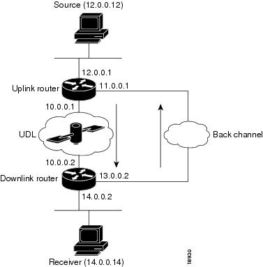
The following example shows how to configure IGMP UDLR. In this example, uplink-rtr is the local upstream router and downlink-rtr is the downstream router. Figure 84 illustrates the example.
Both routers are also connected to each other by a back channel connection. Both routers have two IP addresses: one on the UDL and one on the interface that leads to the back channel. The back channel is any return route and can have any number of routers.
Note
All routers on a UDL must have the same subnet address. If all routers on a UDL cannot have the same subnet address, the upstream router must be configured with secondary addresses to match all the subnets that the downstream routers are attached to.
Figure 84 IGMP Unidirectional Link Routing Example
Uplink Router (uplink-rtr) Configuration
ip multicast-routing!! Interface that source is attached to!interface ethernet 0description Typical IP multicast enabled interfaceip address 12.0.0.1 255.0.0.0ip pim sparse-dense-mode!! Back channel!interface ethernet 1description Back channel which has connectivity to downlink-rtrip address 11.0.0.1 255.0.0.0ip pim sparse-dense-mode!! Unidirectional link!interface serial 0description Unidirectional to downlink-rtrip address 10.0.0.1 255.0.0.0ip pim sparse-dense-modeip igmp unidirectional-linkno keepaliveDownlink Router (downlink-rtr) Configuration
ip multicast-routing!! Interface that receiver is attached to, configure for IGMP reports to be! helpered for the unidirectional interface.!interface ethernet 0description Typical IP multicast-enabled interfaceip address 14.0.0.2 255.0.0.0ip pim sparse-dense-modeip igmp helper-address udl serial 0!! Back channel!interface ethernet 1description Back channel that has connectivity to downlink-rtrip address 13.0.0.2 255.0.0.0ip pim sparse-dense-mode!! Unidirectional link!interface serial 0description Unidirectional to uplink-rtrip address 10.0.0.2 255.0.0.0ip pim sparse-dense-modeip igmp unidirectional-linkno keepaliveIGMP Proxy Example
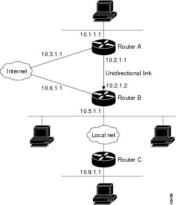
The following example shows how to configure IGMP Proxy. In this example, Router C sends a PIM-SM join message to Router B for multicast group G. Router B will send a request to Router A for an IGMP report for group G. Router A will then forward group G multicast traffic over the UDL. Figure 85 illustrates this example.
Figure 85 IGMP Mroute Proxy Topology
Router A Configuration
interface ethernet 0ip address 10.1.1.1 255.255.255.0ip pim dense-mode!interface ethernet 1ip address 10.2.1.1 255.255.255.0ip pim dense-modeip igmp unidirectional link!interface ethernet 2ip address 10.3.1.1 255.255.255.0Router B Configuration
ip pim rp-address 10.5.1.1 5access-list 5 permit 239.0.0.0 0.255.255.255.255!interface loopback 0ip address 10.7.1.1 255.255.255.0ip pim dense-modeip igmp helper-address udl ethernet 0ip igmp proxy-service!interface ethernet 0ip address 10.2.1.2 255.255.255.0ip pim dense-modeip igmp unidirectional link!interface ethernet 1ip address 10.5.1.1 255.255.255.0ip pim sparse-modeip igmp mroute-proxy loopback 0!interface ethernet 2ip address 10.6.1.1 255.255.255.0Router C Configuration
ip pim rp-address 10.5.1.1 5access-list 5 permit 239.0.0.0 0.255.255.255!interface ethernet 0ip address 10.8.1.1 255.255.255.0ip pim sparse-mode!interface ethernet 1ip address 10.9.1.1 255.255.255.0ip pim sparse-modeIntegrated UDLR Tunnel, IGMP UDLR, and IGMP Proxy Example
The following example shows how to configure UDLR tunnels, IGMP UDLR, and IGMP Proxy on both the upstream and downstream routers sharing a UDL:
Upstream Configuration
ip multicast-routing!!!interface Tunnel0ip address 9.1.89.97 255.255.255.252no ip directed-broadcasttunnel source 9.1.89.97tunnel mode gre multipointtunnel key 5tunnel udlr receive-only Ethernet2/3!interface Ethernet2/0no ip addressshutdown!! user networkinterface Ethernet2/1ip address 9.1.89.1 255.255.255.240no ip directed-broadcastip pim dense-modeip cgmpfair-queue 64 256 128no cdp enableip rsvp bandwidth 1000 100!interface Ethernet2/2ip address 9.1.95.1 255.255.255.240no ip directed-broadcast!! physical send-only interfaceinterface Ethernet2/3ip address 9.1.92.100 255.255.255.240no ip directed-broadcastip pim dense-modeip nhrp network-id 5ip nhrp server-onlyip igmp unidirectional-linkfair-queue 64 256 31ip rsvp bandwidth 1000 100!router ospf 1network 9.1.92.96 0.0.0.15 area 1!ip classlessip route 9.1.90.0 255.255.255.0 9.1.92.99!Downstream Configuration
ip multicast-routing!!!interface Loopback0ip address 9.1.90.161 255.255.255.252ip pim sparse-modeip igmp helper-address udl Ethernet2/3ip igmp proxy-service!interface Tunnel0ip address 9.1.90.97 255.255.255.252ip access-group 120 outno ip directed-broadcastno ip mroute-cachetunnel source 9.1.90.97tunnel destination 9.1.89.97tunnel key 5tunnel udlr send-only Ethernet2/3tunnel udlr address-resolution!interface Ethernet2/0no ip addressno ip directed-broadcastshutdownno cdp enable!! user networkinterface Ethernet2/1ip address 9.1.90.1 255.255.255.240no ip directed-broadcastip pim sparse-modeip igmp mroute-proxy Loopback0no cdp enable!! Backchannelinterface Ethernet2/2ip address 9.1.95.3 255.255.255.240no ip directed-broadcastno cdp enable!! physical receive-only interfaceinterface Ethernet2/3ip address 9.1.92.99 255.255.255.240no ip directed-broadcastip pim sparse-modeip igmp unidirectional-linkno keepaliveno cdp enable!router ospf 1network 9.1.90.0 0.0.0.255 area 1network 9.1.92.96 0.0.0.15 area 1!ip classlessip route 0.0.0.0 0.0.0.0 9.1.95.1! set rpf to be the physical receive-only interfaceip mroute 0.0.0.0 0.0.0.0 9.1.92.96ip pim rp-address 9.1.90.1!! permit ospf, ping and rsvp, deny othersaccess-list 120 permit icmp any anyaccess-list 120 permit 46 any anyaccess-list 120 permit ospf any any