-
Cisco IOS IP Configuration Guide, Release 12.2
-
About Cisco IOS Software Documentation
-
Using Cisco IOS Software
-
IP Overview
- Part 1: IP Addressing Services
- Part 2: IP Routing Protocols
-
Part 3: IP Multicast
-
Configuring IP Multicast Routing
-
Configuring Source Specific Multicast
-
Configuring Bidirectional PIM
-
Configuring Multicast Source Discovery Protocol
-
Configuring PGM Host and Router Assist
-
Configuring Unidirectional Link Routing
-
Using IP Multicast Tools
-
Configuring Router-Port Group Management Protocol
-
Configuring DVMRP Interoperability
-
-
 Feedback
Table Of Contents
Configuring IP Multicast Routing
The Cisco IP Multicast Routing Implementation
Basic IP Multicast Routing Configuration Task List
Advanced IP Multicast Routing Configuration Task List
Configuring PIM Dense Mode State Refresh
Configuring a Rendezvous Point
Setting Up Auto-RP in a New Internetwork
Adding Auto-RP to an Existing Sparse Mode Cloud
Announcing the RP and the Group Range It Serves
Assigning the RP Mapping Agent
Verifying the Group-to-RP Mapping
Preventing Join Messages to False RPs
Filtering Incoming RP Announcement Messages
IGMP Features Configuration Task List
Configuring a Router to Be a Member of a Group
Controlling Access to IP Multicast Groups
Modifying the IGMP Host-Query Message and Query Timeout Intervals
Routers That Run IGMP Version 1
Routers That Run IGMP Version 2
Changing the IGMP Query Timeout
Changing the Maximum Query Response Time
Configuring the Router as a Statically Connected Member
Configuring IGMP Leave Latency
Disabling Fast Switching of IP Multicast
SAP Listener Support Configuration Task List
Limiting How Long a SAP Cache Entry Exists
Enabling the Functional Address for IP Multicast over Token Ring LANs
PIM Version 2 Configuration Task List
Configuring PIM Version 2 Only
Configuring PIM Sparse-Dense Mode
Defining a PIM Sparse Mode Domain Border Interface
Making the Transition to PIM Version 2
Deciding When to Configure a BSR
Monitoring the RP Mapping Information
Advanced PIM Features Configuration Task List
Understanding PIM Shared Tree and Source Tree (Shortest-Path Tree)
Understanding Reverse Path Forwarding
Delaying the Use of PIM Shortest-Path Tree
Assigning an RP to Multicast Groups
Modifying the PIM Router Query Message Interval
Understanding the PIM Registering Process
Limiting the Rate of PIM Register Messages
Configuring the IP Source Address of Register Messages
Enabling PIM Nonbroadcast Multiaccess Mode
Configuring an IP Multicast Static Route
Controlling the Transmission Rate to a Multicast Group
Configuring RTP Header Compression
Enabling RTP Header Compression on a Serial Interface
Enabling RTP Header Compression with Frame Relay Encapsulation
Changing the Number of Header Compression Connections
Enabling Express RTP Header Compression
Configuring IP Multicast over ATM Point-to-Multipoint Virtual Circuits
Enabling IP Multicast over ATM Point-to-Multipoint VCs
Configuring an IP Multicast Boundary
Configuring an Intermediate IP Multicast Helper
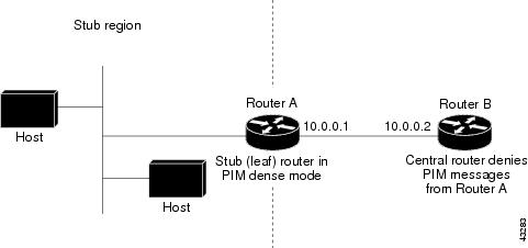
Configuring Stub IP Multicast Routing
Load Splitting IP Multicast Traffic Across Equal-Cost Paths Configuration Task List
Enabling Native Load Splitting
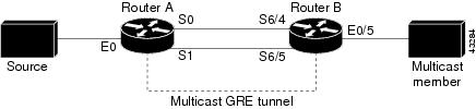
Enabling Load Splitting Across Tunnels
Configuring the Router at the Opposite End of the Tunnel
Configuring Both Routers to RPF
Monitoring and Maintaining IP Multicast Routing Configuration Task List
Clearing Caches, Tables, and Databases
Displaying System and Network Statistics
IP Multicast Configuration Examples
PIM Dense Mode State Refresh Example
Functional Address for IP Multicast over Token Ring LAN Example
Border Router Configuration Example
RFC 2362 Interoperable Candidate RP Example
RTP Header Compression Examples
Express RTP Header Compression with PPP Encapsulation Example
Express RTP Header Compression with Frame Relay Encapsulation Example
IP Multicast over ATM Point-to-Multipoint VC Example
Administratively Scoped Boundary Example
Load Splitting IP Multicast Traffic Across Equal-Cost Paths Example
IP Multicast Heartbeat Example
Configuring IP Multicast Routing
This chapter describes how to configure IP multicast routing. For a complete description of the IP multicast routing commands in this chapter, refer to the "IP Multicast Routing Commands" chapter of the Cisco IOS IP Command Reference, Volume 3 of 3: Multicast. To locate documentation of other commands in this chapter, use the command reference master index, or search online.
Traditional IP communication allows a host to send packets to a single host (unicast transmission) or to all hosts (broadcast transmission). IP multicast provides a third scheme, allowing a host to send packets to a subset of all hosts (group transmission). These hosts are known as group members.
Packets delivered to group members are identified by a single multicast group address. Multicast packets are delivered to a group using best-effort reliability, just like IP unicast packets.
The multicast environment consists of senders and receivers. Any host, regardless of whether it is a member of a group, can send to a group. However, only the members of a group receive the message.
A multicast address is chosen for the receivers in a multicast group. Senders use that address as the destination address of a datagram to reach all members of the group.
Membership in a multicast group is dynamic; hosts can join and leave at any time. There is no restriction on the location or number of members in a multicast group. A host can be a member of more than one multicast group at a time.
How active a multicast group is and what members it has can vary from group to group and from time to time. A multicast group can be active for a long time, or it may be very short-lived. Membership in a group can change constantly. A group that has members may have no activity.
Routers executing a multicast routing protocol, such as Protocol Independent Multicast (PIM), maintain forwarding tables to forward multicast datagrams. Routers use the Internet Group Management Protocol (IGMP) to learn whether members of a group are present on their directly attached subnets. Hosts join multicast groups by sending IGMP report messages.
Many multimedia applications involve multiple participants. IP multicast is naturally suitable for this communication paradigm.
To identify the hardware platform or software image information associated with a feature, use the Feature Navigator on Cisco.com to search for information about the feature or refer to the software release notes for a specific release. For more information, see the "Identifying Supported Platforms" section in the "Using Cisco IOS Software" chapter.
The Cisco IP Multicast Routing Implementation
The Cisco IOS software supports the following protocols to implement IP multicast routing:
•
IGMP is used between hosts on a LAN and the routers on that LAN to track the multicast groups of which hosts are members.
•
•
•
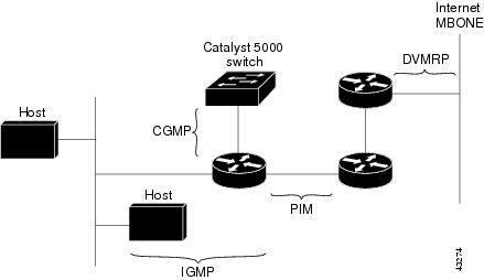
Figure 66 shows where these protocols operate within the IP multicast environment. The protocols are further described in the sections following the figure.
Figure 66 IP Multicast Routing Protocols
IGMP
To start implementing IP multicast routing in your campus network, you must first define who receives the multicast. IGMP provides a means to automatically control and limit the flow of multicast traffic throughout your network with the use of special multicast queriers and hosts.
•
•
A set of queriers and hosts that receive multicast data streams from the same source is called a multicast group. Queries and hosts use IGMP messages to join and leave multicast groups.
IP multicast traffic uses group addresses, which are Class D IP addresses. The high-order four bits of a Class D address are 1110. Therefore, host group addresses can be in the range 224.0.0.0 to 239.255.255.255.
Multicast addresses in the range 224.0.0.0 to 224.0.0.255 are reserved for use by routing protocols and other network control traffic. The address 224.0.0.0 is guaranteed not to be assigned to any group.
IGMP packets are transmitted using IP multicast group addresses as follows:
•
•
•
•
–
IGMP Versions
IGMP messages are used primarily by multicast hosts to signal their interest in joining a specific multicast group and to begin receiving group traffic.
The original IGMP Version 1 Host Membership model defined in RFC 1112 is extended to significantly reduce leave latency and provide control over source multicast traffic by use of Internet Group Management Protocol, Version 2.
•
Provides for the basic Query-Response mechanism that allows the multicast router to determine which multicast groups are active and other processes that enable hosts to join and leave a multicast group. RFC 1112 defines Host Extensions for IP Multicasting.
•
Extends IGMP allowing such features as the IGMP leave process, group-specific queries, and an explicit maximum query response time. IGMP Version 2 also adds the capability for routers to elect the IGMP querier without dependence on the multicast protocol to perform this task. RFC 2236 defines Internet Group Management Protocol, Version 2.
•
Provides for "source filtering" which enables a multicast receiver host to signal to a router which groups it wants to receive multicast traffic from, and from which sources this traffic is expected.
PIM
The PIM protocol maintains the current IP multicast service mode of receiver-initiated membership. It is not dependent on a specific unicast routing protocol.
PIM is defined in RFC 2362, Protocol-Independent Multicast-Sparse Mode (PIM-SM): Protocol Specification. PIM is defined in the following Internet Engineering Task Force (IETF) Internet drafts:
•
•
•
•
•
PIM can operate in dense mode or sparse mode. It is possible for the router to handle both sparse groups and dense groups at the same time.
In dense mode, a router assumes that all other routers want to forward multicast packets for a group. If a router receives a multicast packet and has no directly connected members or PIM neighbors present, a prune message is sent back to the source. Subsequent multicast packets are not flooded to this router on this pruned branch. PIM builds source-based multicast distribution trees.
In sparse mode, a router assumes that other routers do not want to forward multicast packets for a group, unless there is an explicit request for the traffic. When hosts join a multicast group, the directly connected routers send PIM join messages toward the rendezvous point (RP). The RP keeps track of multicast groups. Hosts that send multicast packets are registered with the RP by the first hop router of that host. The RP then sends join messages toward the source. At this point, packets are forwarded on a shared distribution tree. If the multicast traffic from a specific source is sufficient, the first hop router of the host may send join messages toward the source to build a source-based distribution tree.
CGMP
CGMP is a protocol used on routers connected to Catalyst switches to perform tasks similar to those performed by IGMP. CGMP is necessary for those Catalyst switches that cannot distinguish between IP multicast data packets and IGMP report messages, both of which are addressed to the same group address at the MAC level.
Basic IP Multicast Routing Configuration Task List
Basic and advanced IP multicast routing configuration tasks are described in the following sections. The basic tasks in the first two sections are required; the tasks in the remaining sections are optional.
•
•
•
•
•
•
•
•
•
Advanced IP Multicast Routing Configuration Task List
The advanced IP multicast routing tasks described in the following sections are optional:
•
•
•
•
•
•
•
•
•
•
•
•
See the "IP Multicast Configuration Examples" later in this chapter for examples of multicast routing configurations.
To see information on IP multicast multilayer switching, refer to the Cisco IOS Switching Services Configuration Guide and Cisco IOS Switching Services Command Reference.
Enabling IP Multicast Routing
Enabling IP multicast routing allows the Cisco IOS software to forward multicast packets. To enable IP multicast routing on the router, use the following command in global configuration mode:
Enabling PIM on an Interface
Enabling PIM on an interface also enables IGMP operation on that interface. An interface can be configured to be in dense mode, sparse mode, or sparse-dense mode. The mode determines how the router populates its multicast routing table and how the router forwards multicast packets it receives from its directly connected LANs. You must enable PIM in one of these modes for an interface to perform IP multicast routing.
In populating the multicast routing table, dense mode interfaces are always added to the table. Sparse mode interfaces are added to the table only when periodic join messages are received from downstream routers, or when a directly connected member is on the interface. When forwarding from a LAN, sparse mode operation occurs if an RP is known for the group. If so, the packets are encapsulated and sent toward the RP. When no RP is known, the packet is flooded in a dense mode fashion. If the multicast traffic from a specific source is sufficient, the first hop router of the receiver may send join messages toward the source to build a source-based distribution tree.
There is no default mode setting. By default, multicast routing is disabled on an interface.
Enabling Dense Mode
To configure PIM on an interface to be in dense mode, use the following command in interface configuration mode:
See the "PIM Dense Mode Example" section later in this chapter for an example of how to configure a PIM interface in dense mode.
Enabling Sparse Mode
To configure PIM on an interface to be in sparse mode, use the following command in interface configuration mode:
See the "PIM Sparse Mode Example" section later in this chapter for an example of how to configure a PIM interface in sparse mode.
Enabling Sparse-Dense Mode
If you configure either the ip pim sparse-mode or ip pim dense-mode interface configuration command, then sparseness or denseness is applied to the interface as a whole. However, some environments might require PIM to run in a single region in sparse mode for some groups and in dense mode for other groups.
An alternative to enabling only dense mode or only sparse mode is to enable sparse-dense mode. In this case, the interface is treated as dense mode if the group is in dense mode; the interface is treated in sparse mode if the group is in sparse mode. You must have an RP if the interface is in sparse-dense mode, and you want to treat the group as a sparse group.
If you configure sparse-dense mode, the idea of sparseness or denseness is applied to the group on the router, and the network manager should apply the same concept throughout the network.
Another benefit of sparse-dense mode is that Auto-RP information can be distributed in a dense mode manner; yet, multicast groups for user groups can be used in a sparse mode manner. Thus, there is no need to configure a default RP at the leaf routers.
When an interface is treated in dense mode, it is populated in the outgoing interface list of a multicast routing table when either of the following conditions is true:
•
•
When an interface is treated in sparse mode, it is populated in the outgoing interface list of a multicast routing table when either of the following conditions is true:
•
•
To enable PIM to operate in the same mode as the group, use the following command in interface configuration mode:
Router(config-if)# ip pim sparse-dense-mode
Enables PIM to operate in sparse or dense mode, depending on the group.
Configuring PIM Dense Mode State Refresh
If you have PIM dense mode (PIM-DM) enabled on a router interface, the PIM Dense Mode State Refresh feature is enabled by default.
PIM-DM builds source-based multicast distribution trees that operate on a "flood and prune" principle. Multicast packets from a source are flooded to all areas of a PIM-DM network. PIM routers that receive multicast packets and have no directly connected multicast group members or PIM neighbors send a prune message back up the source-based distribution tree toward the source of the packets. As a result, subsequent multicast packets are not flooded to pruned branches of the distribution tree. However, the pruned state in PIM-DM times out approximately every 3 minutes and the entire PIM-DM network is reflooded with multicast packets and prune messages. This reflooding of unwanted traffic throughout the PIM-DM network consumes network bandwidth.
The PIM Dense Mode State Refresh feature keeps the pruned state in PIM-DM from timing out by periodically forwarding a control message down the source-based distribution tree. The control message refreshes the prune state on the outgoing interfaces of each router in the distribution tree.
This feature also enables PIM routers in a PIM-DM multicast network to recognize topology changes (sources joining or leaving a multicast group) before the default 3-minute state refresh timeout period expires.
By default, all PIM routers that are running a Cisco IOS software release that supports the PIM Dense Mode State Refresh feature automatically process and forward state refresh control messages. To disable the processing and forwarding of state refresh control messages on a PIM router, use the ip pim state-refresh disable global configuration command.
To configure the origination of the control messages on a PIM router, use the following commands beginning in global configuration mode:
Note
See the "PIM Dense Mode State Refresh Example" section later in this chapter for an example of how to configure the PIM Dense Mode State Refresh feature.
Configuring a Rendezvous Point
If you configure PIM to operate in sparse mode, you must also choose one or more routers to be rendezvous points (RPs). You need not configure the routers to be RPs; they learn how to become RPs themselves. RPs are used by senders to a multicast group to announce their existence and by receivers of multicast packets to learn about new senders. The Cisco IOS software can be configured so that packets for a single multicast group can use one or more RPs.
The RP address is used by first hop routers to send PIM register messages on behalf of a host sending a packet to the group. The RP address is also used by last hop routers to send PIM join and prune messages to the RP to inform it about group membership. You must configure the RP address on all routers (including the RP router).
A PIM router can be an RP for more than one group. Only one RP address can be used at a time within a PIM domain. The conditions specified by the access list determine for which groups the router is an RP.
To configure the address of the RP, use the following command on a leaf router in global configuration mode:
Router(config)# ip pim rp-address rp-address [access-list] [override]
Configures the address of a PIM RP.
Configuring Auto-RP
Auto-RP is a feature that automates the distribution of group-to-RP mappings in a PIM network. This feature has the following benefits:
•
•
•
Multiple RPs can be used to serve different group ranges or serve as backups of each other. To make Auto-RP work, a router must be designated as an RP-mapping agent, which receives the RP-announcement messages from the RPs and arbitrates conflicts. The RP-mapping agent then sends the consistent group-to-RP mappings to all other routers. Thus, all routers automatically discover which RP to use for the groups they support.
Note
Note
Setting Up Auto-RP in a New Internetwork
If you are setting up Auto-RP in a new internetwork, you do not need a default RP because you configure all the interfaces for sparse-dense mode. Follow the process described in the section "Adding Auto-RP to an Existing Sparse Mode Cloud," except that you should omit the first step of choosing a default RP.
Adding Auto-RP to an Existing Sparse Mode Cloud
The following sections contain suggestions for the initial deployment of Auto-RP into an existing sparse mode cloud, to minimize disruption of the existing multicast infrastructure.
Choosing a Default RP
Sparse mode environments need a default RP; sparse-dense mode environments do not. If you have sparse-dense mode configured everywhere, you need not choose a default RP.
Adding Auto-RP to a sparse mode cloud requires a default RP. In an existing PIM sparse mode region, at least one RP is defined across the network that has good connectivity and availability. That is, the ip pim rp-address command is already configured on all routers in this network.
Use that RP for the global groups (for example, 224.x.x.x and other global groups). There is no need to reconfigure the group address range that RP serves. RPs discovered dynamically through Auto-RP take precedence over statically configured RPs. Assume it is desirable to use a second RP for the local groups.
Announcing the RP and the Group Range It Serves
Find another router to serve as the RP for the local groups. The RP-mapping agent can double as an RP itself. Assign the whole range of 239.x.x.x to that RP, or assign a subrange of that (for example, 239.2.x.x).
To designate that a router is the RP, use the following command in global configuration mode:
Router(config)# ip pim send-rp-announce type number scope ttl-value [group-list access-list] [interval seconds]
Configures a router to be the RP.
To change the group ranges this RP optimally will serve in the future, change the announcement setting on the RP. If the change is valid, all other routers automatically will adopt the new group-to-RP mapping.
The following example advertises the IP address of Ethernet interface 0 as the RP for the administratively scoped groups:
ip pim send-rp-announce ethernet0 scope 16 group-list 1access-list 1 permit 239.0.0.0 0.255.255.255Assigning the RP Mapping Agent
The RP mapping agent is the router that sends the authoritative discovery packets telling other routers which group-to-RP mapping to use. Such a role is necessary in the event of conflicts (such as overlapping group-to-RP ranges).
Find a router whose connectivity is not likely to be interrupted and assign it the role of RP-mapping agent. All routers within time-to-live (TTL) number of hops from the source router receive the Auto-RP discovery messages. To assign the role of RP mapping agent in that router, use the following command in global configuration mode:
Router(config)# ip pim send-rp-discovery scope ttl-value
Assigns the RP mapping agent.
Verifying the Group-to-RP Mapping
To learn if the group-to-RP mapping has arrived, use the following command in EXEC mode on the designated routers:
Router# show ip pim rp [mapping | metric] [rp-address]
Displays active RPs that are cached with associated multicast routing entries. Information learned by configuration or Auto-RP.
Starting to Use IP Multicast
Use your IP multicast application software to start joining and sending to a group.
Preventing Join Messages to False RPs
Note the ip pim accept-rp global configuration commands previously configured throughout the network. If the ip pim accept-rp command is not configured on any router, this problem can be addressed later. In those routers already configured with the ip pim accept-rp command, you must specify the command again to accept the newly advertised RP.
To accept all RPs advertised with Auto-RP and reject all other RPs by default, use the ip pim accept-rp auto-rp command.
If all interfaces are in sparse mode, a default RP is configured to support the two well-known groups 224.0.1.39 and 224.0.1.40. Auto-RP relies on these two well-known groups to collect and distribute RP-mapping information. When this is the case and the ip pim accept-rp auto-rp command is configured, another ip pim accept-rp command accepting the default RP must be configured, as follows:
ip pim accept-rp <default RP address> 1access-list 1 permit 224.0.1.39access-list 1 permit 224.0.1.40Filtering Incoming RP Announcement Messages
To filter incoming RP announcement messages, use the following command in global configuration mode:
Router(config)# ip pim rp-announce-filter rp-list access-list group-list access-list
Filters incoming RP announcement messages.
IGMP Features Configuration Task List
To configure IGMP features, perform the tasks described in the following sections. The tasks in the first section are required; the tasks in the remaining sections are optional.
•
•
•
•
•
•
•
•
For information about configuring IGMP unidirectional link routing (UDLR), see the chapter "Configuring Unidirectional Link Routing" in this document.
Configuring a Router to Be a Member of a Group
Cisco routers can be configured to be members of a multicast group. This strategy is useful for determining multicast reachability in a network. If a device is configured to be a group member and supports the protocol that is being sent to the group, it can respond (to the ping EXEC command, for example). The device responds to ICMP echo request packets addressed to a group of which it is a member. Another example is the multicast traceroute tools provided in the Cisco IOS software.
To have the router join a multicast group and enable IGMP, use the following command in interface configuration mode:
Controlling Access to IP Multicast Groups
Multicast routers send IGMP host query messages to determine which multicast groups have members in the attached local networks of the router. The routers then forward to these group members all packets addressed to the multicast group. You can place a filter on each interface that restricts the multicast groups that hosts on the subnet serviced by the interface can join.
To filter multicast groups allowed on an interface, use the following command in interface configuration mode:
Router(config-if)# ip igmp access-group access-list
Controls the multicast groups that hosts on the subnet serviced by an interface can join.
Changing the IGMP Version
By default, the router uses IGMP Version 2 (IGMPv2), which allows such features as the IGMP query timeout and the maximum query response time.
All routers on the subnet must support the same version. The router does not automatically detect Version 1 routers and switch to Version 1 as did earlier releases of the Cisco IOS software. However, a mix of IGMP Version 1 and Version 2 hosts on the subnet is acceptable. IGMP Version 2 routers will always work correctly in the presence of IGMP Version 1 hosts.
To control which version of IGMP the router uses, use the following command in interface configuration mode:
Router(config-if)# ip igmp version {3 | 2 | 1}
Selects the IGMP version that the router uses.
Modifying the IGMP Host-Query Message and Query Timeout Intervals
Multicast routers send IGMP host-query messages to discover which multicast groups are present on attached networks. These messages are sent to the all-systems group address of 224.0.0.1 with a time-to-live (TTL) of 1.
Multicast routers send host-query messages periodically to refresh their knowledge of memberships present on their networks. If, after some number of queries, the Cisco IOS software discovers that no local hosts are members of a multicast group, the software stops forwarding onto the local network multicast packets from remote origins for that group and sends a prune message upstream toward the source.
Routers That Run IGMP Version 1
If there are multiple routers on a LAN, a designated router (DR) must be elected to avoid duplicating multicast traffic for connected hosts. PIM routers follow an election process to select a DR. The PIM router with the highest IP address becomes the DR.
The DR is responsible for the following tasks:
•
•
By default, the DR sends host-query messages every 60 seconds in order to keep the IGMP overhead on hosts and networks very low.
To modify this interval, use the following command in interface configuration mode:
Router(config-if)# ip igmp query-interval seconds
Configures the frequency at which the designated router sends IGMP host-query messages.
Routers That Run IGMP Version 2
IGMPv2 improved the query messaging capabilities of IGMPv1.
The query and membership report messages in IGMPv2 are identical to the IGMPv1 messages with two exceptions.
1.
2.
Unlike IGMPv1, in which the DR and the IGMP querier are typically the same router; in IGMPv2, the two functions are decoupled. The DR and the IGMP querier are selected based on different criteria and may be different routers on the same subnet. The DR is the router with the highest IP address on the subnet, whereas the IGMP querier is the router with the lowest IP address.
IP addresses in general query messages are used to elect the IGMP querier and this is the election process:
•
•
•
By default, the timer is 2 times the query interval controlled by the ip igmp query-interval command.
To change the query timeout and to specify the period of time before a new election is performed, use the following command in interface configuration mode:
Configuring IGMP Version 3
IGMP Version 3 (IGMPv3) adds support in Cisco IOS software for "source filtering," which enables a multicast receiver host to signal to a router which groups it wants to receive multicast traffic from, and from which sources this traffic is expected. This membership information enables Cisco IOS software to forward traffic only from those sources from which receivers requested the traffic.
IGMPv3 supports applications that explicitly signal sources from which they want to receive traffic. With IGMPv3, receivers signal membership to a multicast host group in the following two modes:
•
•
IGMPv3 is the industry-designated standard protocol for hosts to signal channel subscriptions in Source Specific Multicast (SSM). For SSM to rely on IGMPv3, IGMPv3 must be available in last hop routers and host operating system network stacks, and be used by the applications running on those hosts.
In SSM deployment cases where IGMPv3 cannot be used because it is not supported by the receiver host or the receiver applications, two Cisco-developed transition solutions enable the immediate deployment of SSM services: URL Rendezvous Directory (URD) and IGMP Version 3 lite (IGMP v3lite). For more information on URD and IGMP v3lite, see the "Configuring Source Specific Multicast" chapter in this document.
Restrictions
Traffic Filtering with Multicast Groups That Are Not Configured in SSM Mode
IGMPv3 membership reports are not utilized by Cisco IOS software to filter or restrict traffic for multicast groups that are not configured in SSM mode. Effectively, Cisco IOS software interprets all IGMPv3 membership reports for groups configured in dense, sparse, or bidirectional mode to be group membership reports and forwards traffic from all active sources onto the network.
Interoperability with IGMP Snooping
You must be careful when using IGMPv3 with switches that support and are enabled for IGMP snooping, because IGMPv3 messages are different from the messages used in IGMP Version 1 (IGMPv1) and Version 2 (IGMPv2). If a switch does not recognize IGMPv3 messages, then hosts will not correctly receive traffic if IGMPv3 is being used. In this case, either IGMP snooping may be disabled on the switch or the router may be configured for IGMPv2 on the interface (which would remove the ability to use SSM for host applications that cannot resort to URD or IGMP v3lite).
Interoperability with CGMP
Networks using CGMP will have better group leave behavior if they are configured with IGMPv2 than IGMPv3. If CGMP is used with IGMPv2 and the switch is enabled for the CGMP leave functionality, then traffic to a port joined to a multicast group will be removed from the port shortly after the last member on that port has dropped membership to that group. This fast-leave mechanism is part of IGMPv2 and is specifically supported by the CGMP fast-leave enabled switch.
With IGMPv3, there is currently no CGMP switch support of fast leave. If IGMPv3 is used in a network, CGMP will continue to work, but CGMP fast-leave support is ineffective and the following conditions apply:
•
•
•
This join behavior only applies to multicast groups that actually operate in IGMPv3 mode. If legacy hosts only supporting IGMPv2 are present in the network, then groups will revert to IGMPv2 and fast leave will work for these groups.
If fast leave is needed with CGMP-enabled switches, we recommend that you not enable IGMPv3 but configure IGMPv2 on that interface.
If IGMPv3 is needed to support SSM, then you have two configuration alternatives as follows:
•
•
Changing the IGMP Query Timeout
You can specify the period of time before the router takes over as the querier for the interface, after the previous querier has stopped doing so. By default, the router waits two times the query interval controlled by the ip igmp query-interval interface configuration command. After that time, if the router has received no queries, it becomes the querier. This feature requires IGMP Version 2.
To change the query timeout, use the following command in interface configuration mode:
Changing the Maximum Query Response Time
By default, the maximum query response time advertised in IGMP queries is 10 seconds. If the router is using IGMP Version 2, you can change this value. The maximum query response time allows a router to quickly detect that there are no more directly connected group members on a LAN. Decreasing the value allows the router to prune groups faster.
To change the maximum query response time, use the following command in interface configuration mode:
Router(config-if)# ip igmp query-max-response-time seconds
Sets the maximum query response time advertised in IGMP queries.
Configuring the Router as a Statically Connected Member
Sometimes either there is no group member on a network segment or a host cannot report its group membership using IGMP. However, you may want multicast traffic to go to that network segment. The following are two ways to pull multicast traffic down to a network segment:
•
•
To configure the router itself to be a statically connected member of a group (and allow fast switching), use the following command in interface configuration mode:
Router(config-if)# ip igmp static-group group-address
Configures the router as a statically connected member of a group.
Configuring IGMP Leave Latency
In IGMPv2 and IGMPv3, hosts send IGMP messages to indicate that they do not wish to receive a particular group, source, or channel any more. The length of time between the host wanting to leave and the router stopping forwarding is called the IGMP leave latency. IGMP leave latency is only relevant when the last host on a subnet that was a member to a group, source, or channel intends to leave, because as long as there are still other interested members, the router still needs to forward the traffic.
When a router receives such a membership message that indicates a leave, by default, it needs to verify if there are still other members interested in the traffic. To do so, the IGMP querying router sends out a group-specific or group-source-specific query. This query contains the last member query interval (LMQI), which is the time within which other still interested hosts need to send a membership report or else the router will stop forwarding. Because IGMP messages may get lost between router and hosts, the router by default does not immediately stop forwarding after the LMQI has expired, but instead it repeats this process of sending the group or group-source-specific query and waiting for membership reports for a total of times specified by the last member query count (LMQC). Only thereafter will the router stop forwarding.
By default in Cisco IOS software and in the IGMPv2 and IGMPv3 RFCs, the LMQI is 1 second, and the LMQC is 2. Therefore, the default leave latency for individual leaves in Cisco IOS software is 3 seconds.
IGMPv3 explicit tracking allows to reduce the leave latency to approximately 0 for hosts that support IGMPv3. This feature is not available for hosts that support only IGMPv2 because of the protocol limitation.
In IGMPv2, if there is only one IP multicast receiving host connected to a subnet, the ip igmp immediate-leave group-list command can be configured so the router immediately stop forwarding traffic for the group, resulting in a leave latency of 0.
To change the values of the LMQI, use the following command in interface configuration mode:
To change the values of the LMQC, use the following commands in interface configuration mode:
Router(config-if)# ip igmp last-member-query-count lmqc
Configures the number of times that the router sends IGMP group-specific or group-source-specific (with IGMPv3) query messages.
Configuring the TTL Threshold
The TTL value controls whether packets are forwarded out of an interface. You specify the TTL value in hops. Only multicast packets with a TTL greater than the interface TTL threshold are forwarded on the interface. The default value is 0, which means that all multicast packets are forwarded on the interface. To change the default TTL threshold value, use the following command in interface configuration mode:
Router(config-if)# ip multicast ttl-threshold ttl-value
Configures the TTL threshold of packets being forwarded out an interface.
Disabling Fast Switching of IP Multicast
Fast switching of IP multicast packets is enabled by default on all interfaces (including generic routing encapsulation [GRE] and DVMRP tunnels), with one exception: It is disabled and not supported over X.25 encapsulated interfaces. Note the following properties of fast switching:
•
•
Disable fast switching if you want to log debug messages, because when fast switching is enabled, debug messages are not logged.
To disable fast switching of IP multicast, use the following command in interface configuration mode:
SAP Listener Support Configuration Task List
To configure Session Announcement Protocol (SAP) listener support, perform the tasks described in the following sections. The task in the first section is required; the task in the remaining section is optional.
•
•
Enabling SAP Listener Support
Use session description and announcement protocols and applications to assist the advertisement of multicast multimedia conferences and other multicast sessions and to communicate the relevant session setup information to prospective participants. Sessions are described by the Session Description Protocol (SDP), which is defined in RFC 2327. SDP provides a formatted, textual description of session properties (for example, contact information, session lifetime, and the media) being used in the session (for example, audio, video, and whiteboard) with their specific attributes like TTL scope, group address, and User Datagram Protocol (UDP) port number.
Many multimedia applications rely on SDP for session descriptions. However, they may use different methods to disseminate these session descriptions. For example, IP/TV relies on the Web to disseminate session descriptions to participants. In this example, participants must know of a Web server that provides the session information.
MBONE applications (for example, vic, vat, and wb) and other applications rely on multicast session information sent throughout the network. In these cases, a protocol called Session Announcement Protocol (SAP) is used to transport the SDP session announcements. SAP Version 2 uses the well-known session directory multicast group 224.2.127.254 to disseminate SDP session descriptions for global scope sessions and group 239.255.255.255 for administrative scope sessions.
Note
To enable the Cisco IOS software to listen to Session Directory announcements, use the following command on a multicast-enabled interface in interface configuration mode:
Router(config-if)# ip sap listen
Enables the Cisco IOS software to listen to Session Directory announcements.
Limiting How Long a SAP Cache Entry Exists
By default, entries are deleted 24 hours after they were last received from the network. To limit how long a SAP cache entry stays active in the cache, use the following command in global configuration mode:
Router(config)# ip sap cache-timeout
Limits how long a SAP cache entry stays active in the cache.
Enabling the Functional Address for IP Multicast over Token Ring LANs
By default, IP multicast datagrams on Token Ring LAN segments use the MAC-level broadcast address 0xFFFF.FFFF.FFFF. That default places an unnecessary burden on all devices that do not participate in IP multicast. The IP Multicast over Token Ring LANs feature defines a way to map IP multicast addresses to a single Token Ring MAC address.
This feature defines the Token Ring functional address (0xc000.0004.0000) that should be used over Token Ring. A functional address is a severely restricted form of multicast addressing implemented on Token Ring interfaces. Only 31 functional addresses are available. A bit in the destination MAC address designates it as a functional address.
The implementation used by Cisco complies with RFC 1469, IP Multicast over Token-Ring Local Area Networks.
If you configure this feature, IP multicast transmissions over Token Ring interfaces are more efficient than they formerly were. This feature reduces the load on other machines that do not participate in IP multicast because they do not process these packets.
The following restrictions apply to the Token Ring functional address:
•
•
•
To enable the mapping of IP multicast addresses to the Token Ring functional address 0xc000.0004.0000, use the following command in interface configuration mode:
Router(config-if)# ip multicast use-functional
Enables the mapping of IP multicast addresses to the Token Ring functional address.
For an example of configuring the functional address, see the section "Functional Address for IP Multicast over Token Ring LAN Example" later in this chapter.
Configuring PIM Version 2
PIM Version 2 includes the following improvements over PIM Version 1:
•
•
•
•
•
•
•
PIM Version 1, together with the Auto-RP feature, can perform the same tasks as the PIM Version 2 BSR. However, Auto-RP is a standalone protocol, separate from PIM Version 1, and is Cisco proprietary. PIM Version 2 is a standards track protocol in the IETF. We recommend that you use PIM Version 2.
Note
Either the BSR or Auto-RP should be chosen for a given range of multicast groups. If there are PIM Version 1 routers in the network, do not use the BSR.
The Cisco PIM Version 2 implementation allows interoperability and transition between Version 1 and Version 2, although there might be some minor problems. You can upgrade to PIM Version 2 incrementally. PIM Versions 1 and 2 can be configured on different routers within one network. Internally, all routers on a shared media network must run the same PIM version. Therefore, if a PIM Version 2 router detects a PIM Version 1 router, the Version 2 router downgrades itself to Version 1 until all Version 1 routers have been shut down or upgraded.
PIM uses the BSR to discover and announce RP-set information for each group prefix to all the routers in a PIM domain. This is the same function accomplished by Auto-RP, but the BSR is part of the PIM Version 2 specification.
To avoid a single point of failure, you can configure several candidate BSRs in a PIM domain. A BSR is elected among the candidate BSRs automatically; they use bootstrap messages to discover which BSR has the highest priority. This router then announces to all PIM routers in the PIM domain that it is the BSR.
Routers that are configured as candidate RPs then unicast to the BSR the group range for which they are responsible. The BSR includes this information in its bootstrap messages and disseminates it to all PIM routers in the domain. Based on this information, all routers will be able to map multicast groups to specific RPs. As long as a router is receiving the bootstrap message, it has a current RP map.
Prerequisites
•
•
PIM Version 2 Configuration Task List
There are two approaches to using PIM Version 2. You can use Version 2 exclusively in your network, or migrate to Version 2 by employing a mixed PIM version environment. When deploying PIM Version 2 in your network, use the following guidelines:
•
Note
•
To configure PIM Version 2, perform the tasks described in the following sections. The tasks in the first section are required; the tasks in the remaining sections are optional.
•
•
•
•
Specifying the PIM Version
All systems using Cisco IOS Release 11.3(2)T or later start in PIM Version 2 mode by default. To reenable PIM Version 2 or specify PIM Version 1 for some reason, control the PIM version by using the following command in interface configuration mode:
Configuring PIM Version 2 Only
To configure PIM Version 2 exclusively, perform the tasks described in this section. It is assumed that no PIM Version 1 system exists in the PIM domain.
The first task is recommended. If you configure Auto-RP, none of the other tasks is required to run PIM Version 2. To configure Auto-RP, see the section "Configuring Auto-RP" earlier in this chapter.
If you want to configure a BSR, perform the tasks in the following sections. The tasks is the first section are required; the tasks in the remaining sections are optional.
•
•
•
•
Configuring PIM Sparse-Dense Mode
To configure PIM sparse-dense mode, use the following commands on all PIM routers inside the PIM domain beginning in global configuration mode:
Repeat Steps 2 and 3 for each interface on which you want to run PIM.
Defining a PIM Sparse Mode Domain Border Interface
A border interface in a PIM sparse mode (PIM-SM) domain requires special precautions to avoid exchange of certain traffic with a neighboring domain reachable through that interface, especially if that domain is also running PIM-SM. BSR and Auto-RP messages should not be exchanged between different domains, because routers in one domain may elect RPs in the other domain, resulting in protocol malfunction or loss of isolation between the domains.
To prevent BSR messages from being sent or received through an interface, use the following command in interface configuration mode:
Router(config-if)# ip pim bsr-border
Prevents BSR messages from being sent or received through an interface.
To prevent Auto-RP messages from being sent or received through an interface, use the following commands beginning in global configuration mode. The access list denies packets destined for the 224.0.1.39 and 224.0.1.40 multicast groups. These two groups are specifically assigned to carry Auto-RP information.
Configuring Candidate BSRs
Configure one or more candidate BSRs. The routers to serve as candidate BSRs should be well connected and be in the backbone portion of the network, as opposed to the dialup portion of the network.
Note
To configure a router to be a candidate BSR, use the following command in global configuration mode:
Router(config)# ip pim bsr-candidate type number hash-mask-length [priority]
Configures the router to be a candidate BSR.
Configuring Candidate RPs
Configure one or more candidate RPs. Similar to BSRs, the RPs should also be well connected and in the backbone portion of the network. An RP can serve the entire IP multicast address space or a portion of it. Candidate RPs send candidate RP advertisements to the BSR.
Note
Consider the following scenarios when deciding which routers should be RPs:
•
•
•
To configure a router to be a candidate RP, use the following command in global configuration mode:
Router(config)# ip pim rp-candidate type number [group-list access-list] [priority value]
Configures the router to be a candidate RP.
For examples of configuring PIM Version 2, see the section "PIM Version 2 Examples" later in this chapter.
Note
Making the Transition to PIM Version 2
On each LAN, the Cisco implementation of PIM Version 2 automatically enforces the rule that all PIM messages on a shared LAN are in the same PIM version. To accommodate that rule, if a PIM Version 2 router detects a PIM Version 1 router on the same interface, the Version 2 router downgrades itself to Version 1 until all Version 1 routers have been shut down or upgraded.
Deciding When to Configure a BSR
If there are only Cisco routers in your network (no routers from other vendors), there is no need to configure a BSR. Configure Auto-RP in the mixed PIM Version 1/Version 2 environment.
Note
Dense Mode
Dense mode groups in a mixed Version 1/Version 2 region need no special configuration; they will interoperate automatically.
Sparse Mode
Sparse mode groups in a mixed Version 1/Version 2 region are possible because the Auto-RP feature in Version 1 interoperates with the RP feature of Version 2. Although all PIM Version 2 routers also can use Version 1, we recommend that the RPs be upgraded to Version 2 (or at least upgraded to PIM Version 1 in the Cisco IOS Release 11.3 software).
To ease the transition to PIM Version 2, we also recommend the following configuration:
•
•
If Auto-RP was not already configured in the PIM Version 1 regions, configure Auto-RP. See the section "Configuring Auto-RP" earlier in this chapter.
Monitoring the RP Mapping Information
To monitor the RP mapping information, use the following commands in EXEC mode as needed:
Advanced PIM Features Configuration Task List
To configure PIM features, perform the optional tasks described in the following sections:
•
•
•
•
•
•
•
•
Understanding PIM Shared Tree and Source Tree (Shortest-Path Tree)
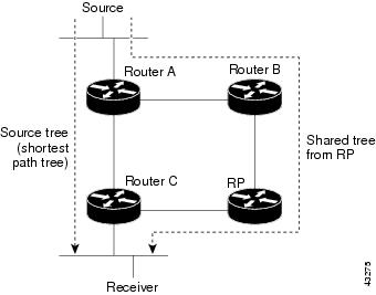
By default, members of a group receive data from senders to the group across a single data distribution tree rooted at the RP. This type of distribution tree is called shared tree, as shown in Figure 67. Data from senders is delivered to the RP for distribution to group members joined to the shared tree.
Figure 67 Shared Tree and Source Tree (Shortest-Path Tree)
If the data rate warrants, leaf routers on the shared tree may initiate a switch to the data distribution tree rooted at the source. This type of distribution tree is called a shortest-path tree or source tree. By default, the Cisco IOS software switches to a source tree upon receiving the first data packet from a source.
The following process describes the move from shared tree to source tree in more detail:
1.
2.
3.
4.
5.
6.
7.
8.
Join and prune messages are sent for sources and RPs. They are sent hop-by-hop and are processed by each PIM router along the path to the source or RP. Register and register-stop messages are not sent hop-by-hop. They are sent by the designated router that is directly connected to a source and are received by the RP for the group.
Multiple sources sending to groups used the shared tree.
The network manager can configure the router to stay on the shared tree, as described in the following section, "Delaying the Use of PIM Shortest-Path Tree."
Understanding Reverse Path Forwarding
Reverse Path Forwarding (RPF) is an algorithm used for forwarding multicast datagrams. It functions as follows:
•
•
•
PIM uses both source trees and RP-rooted shared trees to forward datagrams; the RPF check is performed differently for each, as follows:
•
•
PIM sparse mode uses the RPF lookup function to determine where it needs to send join and prune messages. (S, G) join message (which are source-tree states) are sent toward the source. (*, G) join messages (which are shared-tree states) are sent toward the RP.
DVMRP and PIM dense mode use only source trees and use RPF as described previously.
Delaying the Use of PIM Shortest-Path Tree
The switch from shared to source tree happens upon the arrival of the first data packet at the last hop router (Router C in Figure 67). This switch occurs because the ip pim spt-threshold interface configuration command controls that timing, and its default setting is 0 kbps.
The shortest-path tree requires more memory than the shared tree, but reduces delay. You might want to postpone its use. Instead of allowing the leaf router to move to the shortest-path tree immediately, you can specify that the traffic must first reach a threshold.
You can configure when a PIM leaf router should join the shortest-path tree for a specified group. If a source sends at a rate greater than or equal to the specified kbps rate, the router triggers a PIM join message toward the source to construct a source tree (shortest-path tree). If the infinity keyword is specified, all sources for the specified group use the shared tree, never switching to the source tree.
The group list is a standard access list that controls which groups the shortest-path tree threshold applies to. If a value of 0 is specified or the group list is not used, the threshold applies to all groups.
To configure a traffic rate threshold that must be reached before multicast routing is switched from the source tree to the shortest-path tree, use the following command in global configuration mode:
Router(config)# ip pim spt-threshold {kbps | infinity} [group-list access-list]
Specifies the threshold that must be reached before moving to shortest-path tree.
Assigning an RP to Multicast Groups
If you have configured PIM sparse mode, you must configure a PIM RP for a multicast group. An RP can either be configured statically in each box, or learned through a dynamic mechanism. This section explains how to statically configure an RP. If the RP for a group is learned through a dynamic mechanism (such as Auto-RP), you need not perform this task for that RP. You should use Auto-RP, which is described in the section "Configuring Auto-RP" earlier in this chapter.
PIM designated routers forward data from directly connected multicast sources to the RP for distribution down the shared tree.
Data is forwarded to the RP in one of two ways. It is encapsulated in register packets and unicast directly to the RP, or, if the RP has itself joined the source tree, it is multicast forwarded per the RPF forwarding algorithm described in the preceding section, "Understanding Reverse Path Forwarding." Last hop routers directly connected to receivers may, at their discretion, join themselves to the source tree and prune themselves from the shared tree.
A single RP can be configured for multiple groups defined by an access list. If no RP is configured for a group, the router treats the group as dense using the PIM dense mode techniques.
If a conflict exists between the RP configured with this command and one learned by Auto-RP, the Auto-RP information is used, unless the override keyword is configured.
To assign an RP to one or more multicast groups, use the following command in global configuration mode:
Router(config)# ip pim rp-address rp-address [access-list] [override]
Assigns an RP to multicast groups.
Increasing Control over RPs
You can take a defensive measure to prevent a misconfigured leaf router from interrupting PIM service to the remainder of a network. To do so, configure the local router to accept join messages only if they contain the RP address specified, when the group is in the group range specified by the access list. To configure this feature, use the following command in global configuration mode:
Router(config)# ip pim accept-rp {rp-address | auto-rp} [access-list]
Controls which RPs the local router will accept join messages from.
Modifying the PIM Router Query Message Interval
Router query messages are used to elect a PIM designated router. The designated router is responsible for sending IGMP host query messages. By default, multicast routers send PIM router query messages every 30 seconds. To modify this interval, use the following command in interface configuration mode:
Router(config-if)# ip pim query-interval seconds
Configures the frequency at which multicast routers send PIM router query messages.
Understanding the PIM Registering Process
IP multicast sources do not use a signalling mechanism to announce their presence. Sources just send their data into the attached network, as opposed to receivers that use IGMP to announce their presence. If a source sends traffic to a multicast group configured in PIM-SM, the DR leading toward the source must inform the RP about the presence of this source. If the RP has downstream receivers that want to receive the multicast traffic (natively) from this source and has not joined the shortest path leading toward the source, then the DR must send the traffic from the source to the RP. The PIM registering process, which is individually run for each (S, G) entry, accomplishes these tasks between the DR and RP.
The registering process begins when a DR creates a new (S, G) state. The DR encapsulates all the data packets that match the (S, G) state into PIM register messages and unicasts those register messages to the RP.
If an RP has downstream receivers that want to receive register messages from a new source, the RP can either continue to receive the register messages through the DR or join the shortest path leading toward the source. By default, the RP will join the shortest path, because delivery of native multicast traffic provides the highest throughput. Upon receipt of the first packet that arrives natively through the shortest path, the RP will send a register-stop message back to the DR. When the DR receives this register-stop message, it will stop sending register messages to the RP.
If an RP has no downstream receivers that want to receive register messages from a new source, the RP will not join the shortest path. Instead, the RP will immediately send a register-stop message back to the DR. When the DR receives this register-stop message, it will stop sending register messages to the RP.
Once a routing entry is established for a source, a periodic reregistering takes place between the DR and RP. One minute before the multicast routing table state times out, the DR will send one dataless register message to the RP each second that the source is active until the DR receives a register-stop message from the RP. This action restarts the timeout time of the multicast routing table entry, typically resulting in one reregistering exchange every 2 minutes. Reregistering is necessary to maintain state, to recover from lost state, and to keep track of sources on the RP. It will take place independently of the RP joining the shortest path.
PIM Version 1 Compatibility
If an RP is running PIM Version 1, it will not understand dataless register messages. In this case, the DR will not send dataless register messages to the RP. Instead, approximately every 3 minutes after receipt of a register-stop message from the RP, the DR encapsulates the incoming data packets from the source into register messages and sends them to the RP. The DR continues to send register messages until it receives another register-stop message from the RP. The same behavior occurs if the DR is running PIM Version 1.
When a DR running PIM Version 1 encapsulates data packets into register messages for a specific (S, G) entry, the entry is process-switched, not fast-switched or hardware-switched. On platforms that support these faster paths, the PIM registering process for an RP or DR running PIM Version 1 may lead to periodic out-of-order packet delivery. For this reason, we recommend upgrading your network from PIM Version 1 to PIM Version 2.
Limiting the Rate of PIM Register Messages
To set a limit on the maximum number of PIM-SM register messages sent per second for each (S, G) routing entry, use the following global configuration command on the DR:
Router(config)# ip pim register-rate-limit rate
Sets a limit on the maximum number of PIM-SM register messages sent per second for each (S, G) routing entry.
Dataless register messages are sent at a rate of 1 message per second. Continuous high rates of register messages may occur if a DR is registering bursty sources (sources with high data rates) and if the RP is not running PIM Version 2.
By default, this command is not configured and register messages are sent without limiting their rate. Enabling this command will limit the load on the DR and RP at the expense of dropping those register messages that exceed the set limit. Receivers may experience data packet loss within the first second in which packets are sent from bursty sources.
Configuring the IP Source Address of Register Messages
Register messages are unicast messages sent by the DR to the RP router when a multicast packet needs to be sent on a rendezvous point tree (RPT). By default, the IP source address of the register message is set to the address of the outgoing interface of the DR leading toward the RP. To configure the IP source address of a register message to an interface address other than the outgoing interface address of the DR leading toward the RP, use the following command in global configuration mode:
Router(config)# ip pim register-source type number
Configures the IP source address of a register message.
Enabling Proxy Registering
In a PIM-SM domain, receivers know about sources because the DR connected to the source registers the source with the RP. By default, a DR will only register sources that are connected to it or that are forwarded to the DR from a DVMRP router.
For a router in a PIM-SM domain configured to operate in sparse mode or sparse-dense mode, the ip pim dense-mode proxy-register interface configuration command must be configured on the interface leading toward the bordering dense mode region. This configuration will enable the router to register traffic from the dense mode region with the RP in the sparse mode domain.
To enable proxy registering, use the following command in interface configuration mode:
For traffic from DVMRP neighbors, proxy registering is always active and cannot be influenced by the ip pim dense-mode proxy-register interface configuration command. For dense mode or DVMRP regions, proxy registering allows for limited interoperability between a dense mode region and a sparse mode domain. This limitation is referred to as "receiver must also be sender." The "receiver must also be sender" limit exists because there is no mechanism in dense mode protocols to convey the existence of receiver-only hosts to a border router, and the flooding (and pruning) of all multicast traffic originated in the dense mode domain inhibits the purpose of a sparse mode domain. The behavior of participating hosts in the dense mode region is as follows:
•
•
•
Enabling PIM Nonbroadcast Multiaccess Mode
PIM nonbroadcast multiaccess (NBMA) mode allows the Cisco IOS software to replicate packets for each neighbor on the NBMA network. Traditionally, the software replicates multicast and broadcast packets to all "broadcast" configured neighbors. This action might be inefficient when not all neighbors want packets for certain multicast groups. NBMA mode enables you to reduce bandwidth on links leading into the NBMA network, and to reduce the number of CPU cycles in switches and attached neighbors.
Configure this feature on ATM, Frame Relay, Switched Multimegabit Data Service (SMDS), PRI ISDN, or X.25 networks only, especially when these media do not have native multicast available. Do not use this feature on multicast-capable LANs (such as Ethernet or FDDI).
You should use PIM sparse mode with this feature. Therefore, when each join message is received from NBMA neighbors, PIM stores each neighbor IP address and interface in the outgoing interface list for the group. When a packet is destined for the group, the software replicates the packet and unicasts (data-link unicasts) it to each neighbor that has joined the group.
To enable PIM NBMA mode on your serial link, use the following command in interface configuration mode:
Consider the following two factors before enabling PIM NBMA mode:
•
•
Configuring an IP Multicast Static Route
IP multicast static routes (mroutes) allow you to have multicast paths diverge from the unicast paths. When using PIM, the router expects to receive packets on the same interface where it sends unicast packets back to the source. This expectation is beneficial if your multicast and unicast topologies are congruent. However, you might want unicast packets to take one path and multicast packets to take another.
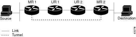
The most common reason for using separate unicast and multicast paths is tunneling. When a path between a source and a destination does not support multicast routing, a solution is to configure two routers with a GRE tunnel between them. In Figure 68, each unicast router (UR) supports unicast packets only; each multicast router (MR) supports multicast packets.
Figure 68 Tunnel for Multicast Packets
In Figure 68, Source delivers multicast packets to Destination by using MR 1 and MR 2. MR 2 accepts the multicast packet only if it believes it can reach Source over the tunnel. If this situation is true, when Destination sends unicast packets to Source, MR 2 sends them over the tunnel. Sending the packet over the tunnel could be slower than natively sending the it through UR 2, UR 1, and MR 1.
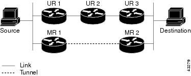
Prior to multicast static routes, the configuration in Figure 69 was used to overcome the problem of both unicasts and multicasts using the tunnel. In this figure, MR 1 and MR 2 are used as multicast routers only. When Destination sends unicast packets to Source, it uses the (UR 3, UR 2, UR 1) path. When Destination sends multicast packets, the UR routers do not understand or forward them. However, the MR routers forward the packets.
Figure 69 Separate Paths for Unicast and Multicast Packets
To make the configuration in Figure 69 work, MR 1 and MR 2 must run another routing protocol (typically a different instantiation of the same protocol running in the UR routers), so that paths from sources are learned dynamically.
A multicast static route allows you to use the configuration in Figure 68 by configuring a static multicast source. The Cisco IOS software uses the configuration information instead of the unicast routing table. Therefore, multicast packets can use the tunnel without having unicast packets use the tunnel. Static mroutes are local to the router they are configured on and not advertised or redistributed in any way to any other router.
To configure a multicast static route, use the following command in global configuration mode:
Router(config)# ip mroute source-address mask [protocol as-number] {rpf-address | type number} [distance]
Configures an IP multicast static route.
Controlling the Transmission Rate to a Multicast Group
By default, there is no limit as to how fast a sender can send packets to a multicast group. To control the rate that the sender from the source list can send to a multicast group in the group list, use the following command in interface configuration mode:
Router(config-if)# ip multicast rate-limit {in | out} [video | whiteboard] [group-list access-list] [source-list access-list] kbps
Controls transmission rate to a multicast group.
Configuring RTP Header Compression
Real-Time Transport Protocol (RTP) is a protocol used for carrying packetized audio and video traffic over an IP network. RTP, described in RFC 1889, is not intended for data traffic, which uses TCP or UDP. RTP provides end-to-end network transport functions intended for applications with real-time requirements (such as audio, video, or simulation data over multicast or unicast network services).
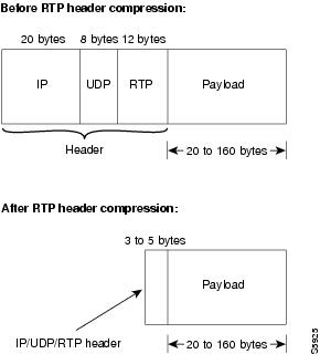
The minimal 12 bytes of the RTP header, combined with 20 bytes of IP header and 8 bytes of UDP header, create a 40-byte IP/UDP/RTP header, as shown in Figure 70. The RTP packet has a payload of approximately 20 to 150 bytes for audio applications that use compressed payloads. It is very inefficient to send the IP/UDP/RTP header without compressing it.
Figure 70 RTP Header Compression
The RTP header compression feature compresses the IP/UDP/RTP header in an RTP data packet from 40 bytes to approximately 2 to 5 bytes, as shown in Figure 70. It is a hop-by-hop compression scheme similar to RFC 1144 for TCP/IP header compression. Using RTP header compression can benefit both telephony voice and MBONE applications running over slow links.
RTP header compression is supported on serial lines using Frame Relay, High-Level Data Link Control (HDLC), or PPP encapsulation. It is also supported over ISDN interfaces.
Enabling compression on both ends of a low-bandwidth serial link can greatly reduce the network overhead if substantial amounts of RTP traffic are on that slow link. This compression is beneficial especially when the RTP payload size is small (for example, compressed audio payloads of 20 to 50 bytes). Although the MBONE-style RTP traffic has higher payload sizes, compact encodings such as code excited linear prediction (CELP) compression can also help considerably.
Before you can enable RTP header compression, you must have configured a serial line that uses either Frame Relay, HDLC, or PPP encapsulation, or an ISDN interface. To configure RTP header compression, perform the tasks described in the following sections. Either one of the first two tasks is required.
•
•
•
You can compress the IP/UDP/RTP headers of RTP traffic to reduce the size of your packets, making audio or video communication more efficient. You must enable compression on both ends of a serial connection.
RTP header compression occurs in either the fast-switched or CEF-switched path, depending on whether certain prerequisites are met. Otherwise, it occurs in the process-switched path. For more information about where RTP header compression occurs, see the section "Enabling Express RTP Header Compression" later in this document.
Enabling RTP Header Compression on a Serial Interface
To enable RTP header compression for serial encapsulation HDLC or PPP, use the following command in interface configuration mode:
Router(config-if)# ip rtp header-compression [passive]
Enables RTP header compression.
If you include the passive keyword, the software compresses outgoing RTP packets only if incoming RTP packets on the same interface are compressed. If you use the command without the passive keyword, the software compresses all RTP traffic.
See the "RTP Header Compression Examples" section later in this chapter for an example of how to enable RTP header compression on a serial interface.
Enabling RTP Header Compression with Frame Relay Encapsulation
To enable RTP header compression with Frame Relay encapsulation, use the following commands in interface configuration mode as needed:
See the "RTP Header Compression Examples" section later in this chapter for an example of how to enable RTP header compression with Frame Relay encapsulation.
To disable RTP and TCP header compression with Frame Relay encapsulation, use the following command in interface configuration mode:
Router(config-if)# frame-relay map ip ip-address dlci [broadcast] nocompress
Disables both RTP and TCP header compression on this link.
Changing the Number of Header Compression Connections
For Frame Relay encapsulation, the software does not specify a maximum number of RTP header compression connections. You can configure from 3 to 256 RTP header compression connections on an interface.
By default, for PPP or HDLC encapsulation, the software allows 32 RTP header compression connections (16 calls). This default can be increased to a maximum of 1000 RTP header compression connections on an interface.
To change the number of compression connections supported, use the following command in interface configuration mode:
See the "RTP Header Compression Examples" section later in this chapter for an example of how to change the number of header compression connections.
Enabling Express RTP Header Compression
Before Cisco IOS Release 12.0(7)T, if compression of TCP or RTP headers was enabled, compression was performed in the process-switching path, which meant that packets traversing interfaces that had TCP or RTP header compression enabled were queued and passed up to the process to be switched. This procedure slowed down transmission of the packet, and therefore some users preferred to fast switch uncompressed TCP and RTP packets.
With Release 12.1 and later releases, if TCP or RTP header compression is enabled, it occurs by default in the fast-switched path or the Cisco Express Forwarding-switched (CEF-switched) path, depending on which switching method is enabled on the interface.
If neither fast switching nor CEF switching is enabled, if enabled, RTP header compression will occur in the process-switched path as before.
For examples of RTP header compression, see the sections "Express RTP Header Compression with PPP Encapsulation Example" and "Express RTP Header Compression with Frame Relay Encapsulation Example."
The Express RTP and TCP Header Compression feature has the following benefits:
•
•
One restriction affects Multilink PPP (MLP) interfaces that have link fragment and interleave (LFI). In this case, if RTP header compression is configured, RTP packets originating on or destined to the router will be process switched. Transit traffic will be fast switched.
The CEF and fast-switching aspects of this feature are related to these documents:
•
•
In order for the Express RTP Header Compression feature to work, the following conditions must exist:
•
•
•
The Express RTP Header Compression feature supports the following RFCs:
•
•
•
Configuring IP Multicast over ATM Point-to-Multipoint Virtual Circuits
IP multicast over ATM point-to-multipoint virtual circuits (VCs) is a feature that dynamically creates ATM point-to-multipoint switched virtual circuits (SVCs) to handle IP multicast traffic more efficiently.
The feature can enhance router performance and link utilization because packets are not replicated and sent multiple times over the ATM interface.
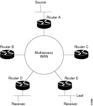
Traditionally, over NBMA networks, Cisco routers would perform a pseudobroadcast to get broadcast or multicast packets to all neighbors on a multiaccess network. For example, assume in Figure 71 that routers A, B, C, D, and E were running the Open Shortest Path First (OSPF) protocol. Router A must deliver to Routers D and E. When Router A sends an OSPF hello packet, the data link layer replicates the hello packet and sends one to each neighbor (this procedure is known as pseudobroadcast), which results in four copies being sent over the link from Router A to the multiaccess WAN.
Figure 71 Environment for IP Multicast over ATM Point-to-Multipoint VCs
With the advent of IP multicast, where high-rate multicast traffic can occur, that approach does not scale. Furthermore, in the preceding example, routers B and C would get data traffic they do not need. To handle this problem, PIM can be configured in NBMA mode using the ip pim nbma-mode interface configuration command. PIM in NBMA mode works only for sparse mode groups. Configuring PIM in NBMA mode would allow only routers D and E to get the traffic without distributing to routers B and C. However, two copies are still delivered over the link from Router A to the multiaccess WAN.
If the underlying network supported multicast capability, the routers could handle this situation more efficiently. If the multiaccess WAN were an ATM network, IP multicast could use multipoint VCs.
To configure IP multicast using multipoint VCs, routers A, B, C, D, and E in Figure 71 must run PIM sparse mode. If the Receiver directly connected to Router D joins a group and A is the PIM RP, the following sequence of events occur:
1.
2.
3.
4.
5.
If a host sends an IGMP report over an ATM interface to a router, the router adds the host to the multipoint VC for the group.
This feature can also be used over ATM subinterfaces.
You must have ATM configured for multipoint signalling. Refer to the "Configuring ATM" chapter in the Cisco IOS Wide-Area Networking Configuration Guide for more information on how to configure ATM for point-to-multipoint signalling.
You also must have IP multicast routing and PIM sparse mode configured. This feature does not work with PIM dense mode.
To configure IP multicast over ATM point-to-multipoint VCs, perform the tasks described in the following sections. The task in the first section is required; the task in the remaining section is optional.
•
•
Enabling IP Multicast over ATM Point-to-Multipoint VCs
To enable PIM to open ATM point-to-multipoint VCs for each multicast group that a receiver joins, use the following commands in interface configuration mode on the ATM interface:
The atm multipoint-signaling interface configuration command is required so that static map multipoint VCs can be opened. The router uses existing static map entries that include the broadcast keyword to establish multipoint calls. You must have the map list to act like a static ARP table.
Use the show ip pim vc EXEC command to display ATM VC status information for multipoint VCs opened by PIM.
See the "IP Multicast over ATM Point-to-Multipoint VC Example" section later in this chapter for an example of how to enable IP multicast over ATM point-to-multipoint VCs.
Limiting the Number of VCs
By default, PIM can open a maximum of 200 VCs. When the router reaches this number, it deletes inactive VCs so it can open VCs for new groups that might have activity. To change the maximum number of VCs that PIM can open, use the following command in interface configuration mode:
Router(config-if)# ip pim vc-count number
Changes the maximum number of VCs that PIM can open.
Idling Policy
An idling policy uses the ip pim vc-count number interface configuration command to limit the number of VCs created by PIM. When the router stays at or below this number value, no idling policy is in effect. When the next VC to be opened will exceed the number value, an idling policy is exercised. An idled VC does not mean that the multicast traffic is not forwarded; the traffic is switched to VC 0. The VC 0 is the broadcast VC that is open to all neighbors listed in the map list. The name "VC 0" is unique to PIM and the mrouting table.
How the Idling Policy Works
The idling policy works as follows:
•
•
•
•
•
•
•
Keeping VCs from Idling
You can configure the minimum rate required to keep VCs from being idled. By default, all VCs are eligible for idling. To configure a minimum rate, use the following command in interface configuration mode:
Router(config-if)# ip pim minimum-vc-rate pps
Sets the minimum activity rate required to keep VCs from being idled.
Configuring an IP Multicast Boundary
You can set up an administratively scoped boundary on an interface for multicast group addresses. A standard access list defines the range of addresses affected. When a boundary is set up, no multicast data packets are allowed to flow across the boundary from either direction. The boundary allows the same multicast group address to be reused in different administrative domains.
The Internet Assigned Numbers Authority (IANA) has designated the multicast address range 239.0.0.0 to 239.255.255.255 as the administratively scoped addresses. This range of addresses can be reused in domains administered by different organizations. They would be considered local, not globally unique.
You can configure the filter-autorp keyword to examine and filter Auto-RP discovery and announcement messages at the administratively scoped boundary. Any Auto-RP group range announcements from the Auto-RP packets that are denied by the boundary access control list (ACL) are removed. An Auto-RP group range announcement is permitted and passed by the boundary only if all addresses in the Auto-RP group range are permitted by the boundary ACL. If any address is not permitted, the entire group range is filtered and removed from the Auto-RP message before the Auto-RP message is forwarded.
To set up an administratively scoped boundary, use the following commands beginning in global configuration mode:
See the section "Administratively Scoped Boundary Example" later in this chapter for an example of configuring a boundary.
Configuring an Intermediate IP Multicast Helper
When a multicast-capable internetwork is between two subnets with broadcast-only-capable hosts, you can convert broadcast traffic to multicast at the first hop router, and convert it back to broadcast at the last hop router to deliver the packets to the broadcast clients. Thus, you can take advantage of the multicast capability of the intermediate multicast internetwork. Configuring an intermediate IP multicast helper prevents unnecessary replication at the intermediate routers and can take advantage of multicast fast switching in the multicast internetwork.
See Figure 73 and the example of this feature in the section "IP Multicast Helper Example" later in this chapter.
An extended IP access list controls which broadcast packets are translated, based on the UDP port number.
To configure an intermediate IP multicast helper, the first hop router and the last hop router must be configured. To configure the first hop router, use the following commands beginning in global configuration mode:
After configuring the first hop router, use the following commands on the last hop router beginning in global configuration mode:
Storing IP Multicast Headers
You can store IP multicast packet headers in a cache and then display them to determine any of the following information:
•
•
•
•
•
•
•
To allocate a circular buffer to store IP multicast packet headers that the router receives, use the following command in global configuration mode:
Router(config)# ip multicast cache-headers
Allocates a buffer to store IP multicast packet headers.
Note
Use the show ip mpacket EXEC command to display the buffer.
Enabling CGMP
CGMP is a protocol used on routers connected to Catalyst switches to perform tasks similar to those performed by IGMP. CGMP is necessary because the Catalyst switch cannot distinguish between IP multicast data packets and IGMP report messages, which are both at the MAC level and are addressed to the same group address.
Enabling CGMP triggers a CGMP join message. CGMP should be enabled only on 802 or ATM media, or LAN emulation (LANE) over ATM. CGMP should be enabled only on routers connected to Catalyst switches.
To enable CGMP for IP multicast on a LAN, use the following command in interface configuration mode:
When the proxy keyword is specified, the CGMP proxy function is enabled. That is, any router that is not CGMP-capable will be advertised by the proxy router. The proxy router advertises the existence of other non-CGMP-capable routers by sending a CGMP join message with the MAC address of the non-CGMP-capable router and group address of 0000.0000.0000.
Configuring Stub IP Multicast Routing
When you use PIM in a large network, there are often stub regions over which the administrator has limited control. To reduce the configuration and administration burden, you can configure a subset of PIM functionality that provides the stub region with connectivity, but does not allow it to participate in or potentially complicate any routing decisions.
Stub IP multicast routing allows simple multicast connectivity and configuration at stub networks. It eliminates periodic flood-and-prune behavior across slow-speed links (ISDN and below) using dense mode. It eliminates that behavior by using forwarded IGMP reports as a type of join message and using selective PIM message filtering.
Stub IP multicast routing allows stub sites to be configured quickly and easily for basic multicast connectivity, without the flooding of multicast packets and subsequent group pruning that occurs in dense mode, and without excessive administrative burden at the central site.
Before configuring stub IP multicast routing, you must have IP multicast routing configured on both the stub router and the central router. You must also have PIM dense mode configured on both the incoming and outgoing interfaces of the stub router.
Two steps are required to enable stub IP multicast routing. One task is performed on the stub router, and the other is performed on a central router one hop away from the stub router. By definition, a stub region is marked by a leaf router. That is, the stub router (leaf router) is the last stop before any hosts receiving multicast packets or the first stop for anyone sending multicast packets.
The first step is to configure the stub router to forward all IGMP host reports and leave messages received on the interface to an IP address. The reports are re-sent out the next hop interface toward the IP address, with the source address of that interface. This action enables a sort of "dense mode" join message, allowing stub sites not participating in PIM to indicate membership in multicast groups.
To configure the stub router to forward IGMP host reports and leave messages, use the following command in interface configuration mode. Specify the IP address of an interface on the central router. When the central router receives IGMP host report and leave messages, it appropriately adds or removes the interface from its outgoing list for that group.
Router(config-if)# ip igmp helper-address ip-address
On the stub router, forwards all IGMP host reports and leave messages to the specified IP address on a central router.
The second step is to configure an access list on the central router to filter all PIM control messages from the stub router. Thus, the central router does not by default add the stub router to its outgoing interface list for any multicast groups. This task has the side benefit of preventing a misconfigured PIM neighbor from participating in PIM.
To filter PIM control messages, use the following command in interface configuration mode:
Router(config-if)# ip pim neighbor-filter access-list
On the central router, filters all PIM control messages based on the specified access list.
For an example of stub IP multicast routing, see the section "Stub IP Multicast Example" later in this chapter.
Load Splitting IP Multicast Traffic Across Equal-Cost Paths Configuration Task List
To configure load splitting of IP multicast traffic across equal-cost paths, perform the optional tasks described in either of the following sections:
•
•
Enabling Native Load Splitting
If two or more equal-cost paths from a source are available, unicast traffic will be load split across those paths. However, by default multicast traffic will not be load split across multiple equal-cost paths. In general, multicast traffic will flow down from the RPF neighbor. According to PIM specifications, this neighbor must have the highest IP address if more than one neighbor has the same metric (refer to RFC 2362 for PIM sparse mode information).
To enable load splitting of IP multicast traffic across multiple equal-cost paths, use the following command in global configuration mode:
Router(config)# ip multicast multipath
Enables load splitting of IP multicast traffic across multiple equal-cost paths.
When the ip multicast multipath global configuration command is configured and multiple equal-cost paths exist, the path in which multicast traffic will travel is selected based on the source IP address. Multicast traffic from different sources will be load split across the different equal-cost paths. Load splitting will not occur across equal-cost paths for multicast traffic from the same source sent to different multicast groups.
Note
The ip multicast multipath command does not support configurations in which the same PIM neighbor IP address is reachable through multiple equal-cost paths. This situation typically occurs if unnumbered interfaces are used. We recommend using different IP addresses for all interfaces when configuring the ip multicast multipath command.
Enabling Load Splitting Across Tunnels
Load splitting of IP multicast traffic can be achieved by consolidating multiple parallel links into a single tunnel over which the multicast traffic is then routed. Figure 72 shows an example of a topology in which this method can be used. Router A and Router B are connected with two equal-cost links.
Figure 72 Two Multicast Links Without Load Splitting
If a tunnel is configured between Router A and Router B, and multicast traffic is made to reverse path forward over the tunnel, then the multicast packets are sent encapsulated into the tunnel as unicast packets between Router A and Router B. The underlying unicast mechanism will then perform load splitting across the equal-cost links.
To configure load splitting across tunnels, perform the tasks described in the following sections. The tasks in the first three sections are required; the task in the remaining section is optional.
•
•
•
•
Configuring the Access Router
To configure the access router end of the tunnel (the end of the tunnel near the source), use the following commands beginning in global configuration mode. The tunnel mode is GRE IP by default.
Configuring the Router at the Opposite End of the Tunnel
After configuring the access router end of the tunnel, use the following commands on the router at the opposite end of the tunnel beginning in global configuration mode:
Configuring Both Routers to RPF
Because the use of the tunnel makes the multicast topology incongruent with the unicast topology, and only multicast traffic traverses the tunnel, you must configure the routers to reverse path forward correctly over the tunnel. The following sections describe two ways to configure the routers to reverse path forward multicast traffic over the tunnel, depending on your topology:
•
•
Load Splitting to a Stub Network
To load split to a stub network using a static multicast router, use the following command on the stub router in global configuration mode:
Router(config)# ip mroute 0.0.0.0 0.0.0.0 tunnel number
Configures a static multicast route over which to reverse path forward from the stub router to the other end of the tunnel.
After configuring a static multicast route, use the following commands on the router at the opposite end of the tunnel from the stub router in global configuration mode:
Load Splitting to the Middle of a Network
You can also use static mroutes to load split to the middle of a network, but you must make sure that Router A would reverse path forward to the tunnel for source networks behind Router B, and Router B would reverse path forward to the tunnel for source networks behind Router A.
Another option is to run a separate unicast routing protocol with a better administrative distance to provide the RPF. You must make sure that your multicast routers do not advertise the tunnel to your real network. For details, refer to the "Configuring an IP Multicast Static Route" section in this chapter.
If you are using a DVMRP routing table for RPF information within your network, you could configure the ip dvmrp unicast-routing interface configuration command on your tunnel interfaces to make the routers reverse path forward correctly over the tunnel.
Verifying the Load Splitting
Load splitting works for both fast switching and process switching, but splitting the traffic among the physical interfaces is performed differently for each case. Fast switching occurs if both the incoming and outgoing interfaces are configured with the ip mroute-cache interface configuration command. IP multicast fast switching is enabled by default. Note the following properties of load splitting:
•
•
In the case of fast switching, you can verify that load splitting is occurring by viewing the multicast fast-switched cache by using the show ip mcache EXEC command. The flows should be split among the underlying interfaces, as shown in the following example:
Router# show ip mcacheIP Multicast Fast-Switching Cache(100.1.1.6/32, 224.1.1.1), Ethernet0, Last used: 00:00:00Tunnel0 MAC Header: 0F000800 (Serial1)(100.1.1.6/32, 224.1.1.2), Ethernet0, Last used: 00:00:00Tunnel0 MAC Header: 0F000800 (Serial1)(100.1.1.5/32, 224.1.1.3), Ethernet0, Last used: 00:00:00Tunnel0 MAC Header: 0F000800 (Serial0)(100.1.1.5/32, 224.1.1.4), Ethernet0, Last used: 00:00:00Tunnel0 MAC Header: 0F000800 (Serial0)For an example of load splitting IP multicast traffic across equal-cost paths, see the section "Load Splitting IP Multicast Traffic Across Equal-Cost Paths Example" later in this chapter.
Monitoring and Maintaining IP Multicast Routing Configuration Task List
To monitor and maintain IP multicast routing, perform the optional tasks described in the following sections.
•
•
•
Note
Clearing Caches, Tables, and Databases
You can remove all contents of a particular cache, table, or database. Clearing a cache, table, or database can become necessary when the contents of the particular structure have become, or are suspected to be, invalid.
To clear IP multicast caches, tables, and databases, use the following commands in EXEC mode as needed:
Displaying System and Network Statistics
You can display specific statistics such as the contents of IP routing tables, caches, and databases. Information provided can be used to determine resource utilization and solve network problems. You can also display information about node reachability and discover the routing path the packets of your device are taking through the network.
To display various routing statistics, use the following commands in EXEC mode, as needed:
Using IP Multicast Heartbeat
The IP multicast heartbeat feature enables you to monitor the delivery of IP multicast packets and to be alerted if the delivery fails to meet certain parameters.
Although you can also use MRM to monitor IP multicast, you can perform the following tasks with IP multicast heartbeat that you cannot do with MRM:
•
•
When IP multicast heartbeat is enabled, the router monitors IP multicast packets destined for a particular multicast group at a particular interval. If the number of packets observed is less than a configured minimum amount, the router sends an Simple Network Management Protocol (SNMP) trap to a specified network management station to indicate a loss of heartbeat exception.
To configure IP multicast heartbeat, use the following commands in global configuration mode:
See the "IP Multicast Heartbeat Example" section later in this chapter for an example of how to configure IP multicast heartbeat.
For more information on the information contained in IP multicast SNMP notifications, refer to the Cisco IOS Configuration Fundamentals Command Reference.
IP Multicast Configuration Examples
This section provides the following IP multicast routing configuration examples:
•
•
•
•
•
•
•
PIM Dense Mode Example
The following example configures PIM dense mode on Fast Ethernet interface 0/1 of the router:
ip multicast-routinginterface FastEthernet0/1ip address 172.16.8.1 255.255.255.0ip pim dense-modePIM Sparse Mode Example
The following example configures the Cisco IOS software to operate in PIM sparse mode. The RP router is the router whose address is 10.8.0.20.
ip multicast-routingip pim rp-address 10.8.0.20 1interface ethernet 1ip pim sparse-modePIM Dense Mode State Refresh Example
The following example shows a PIM router that is originating, processing, and forwarding PIM Dense Mode State Refresh control messages on Fast Ethernet interface 0/1 every 60 seconds:
ip multicast-routinginterface FastEthernet0/1ip address 172.16.8.1 255.255.255.0ip pim state-refresh origination-interval 60ip pim dense-modeThe following example shows a PIM router that is processing and forwarding PIM Dense Mode State Refresh control messages and not originating messages on Fast Ethernet interface 1/1:
ip multicast-routinginterface FastEthernet1/1ip address 172.16.7.3 255.255.255.0ip pim dense-modeFunctional Address for IP Multicast over Token Ring LAN Example
In the following example, any IP multicast packets going out Token Ring interface 0 are mapped to MAC address 0xc000.0004.0000:
interface token 0ip address 1.1.1.1 255.255.255.0ip pim dense-modeip multicast use-functionalPIM Version 2 Examples
This section provides examples in the following sections:
•
•
BSR Configuration Example
The following example is a configuration for a candidate BSR, which also happens to be a candidate RP:
version 11.3!ip multicast-routing!interface Ethernet0ip address 171.69.62.35 255.255.255.240!interface Ethernet1ip address 172.21.24.18 255.255.255.248ip pim sparse-dense-mode!interface Ethernet2ip address 172.21.24.12 255.255.255.248ip pim sparse-dense-mode!router ospf 1network 172.21.24.8 0.0.0.7 area 1network 172.21.24.16 0.0.0.7 area 1!ip pim bsr-candidate Ethernet2 30 10ip pim rp-candidate Ethernet2 group-list 5access-list 5 permit 239.255.2.0 0.0.0.255Border Router Configuration Example
The following example shows how to configure a border router in a PIM-SM domain on Ethernet interface 1. The ip pim bsr-border interface configuration command will prevent BSR messages from being sent or received through the interface. The ip multicast boundary interface configuration command and access list 1 will prevent Auto-RP messages from being sent or received through the interface.
version 12.0!ip multicast-routing!interface Ethernet0ip address 171.69.62.35 255.255.255.240!interface Ethernet1ip address 172.21.24.18 255.255.255.248ip pim sparse-dense-modeip pim bsr-borderip multicast boundary 1!! Access list to deny Auto-RP (224.0.1.39, 224.0.1.40) and! all administrately scoped multicast groups (239.X.X.X)access-list 1 deny 239.0.0.0 0.255.255.255access-list 1 deny 224.0.1.39access-list 1 deny 224.0.1.40access-list 1 permit 224.0.0.0 15.255.255.255RFC 2362 Interoperable Candidate RP Example
When Cisco and non-Cisco routers are being operated in a single PIM domain with PIM Version 2 BSR, care must be taken when configuring candidate RPs because the Cisco IOS implementation of the BSR RP selection is not fully compatible with RFC 2362.
RFC 2362 specifies that the BSR RP be selected as follows (RFC 2362, 3.7):
Step 1
Step 2
Step 3
Cisco routers always select the candidate RP based on the longest match on the announced group address prefix before selecting an RP based on priority, hash function, or IP address.
Inconsistent candidate RP selection between Cisco and non-Cisco RFC 2362-compliant routers in the same domain if multiple candidate RPs with partially overlapping group address ranges are configured can occur. Inconsistent candidate RP selection can lead to disconnectivity between sources and receivers in the PIM domain. A source may register with one candidate RP and a receiver may connect to a different candidate RP even though it is in the same group.
The following example shows a configuration that can cause inconsistent RP selection between a Cisco and a non-Cisco router in a single PIM domain with PIM Version 2 BSR:
access-list 10 permit 224.0.0.0 7.255.255.255ip pim rp-candidate ethernet1 group-list 10 priority 20access-list 20 permit 224.0.0.0 15.255.255.255ip pim rp-candidate ethernet2 group-list 20 priority 10In this example, a candidate RP on Ethernet interface 1 announces a longer group prefix of 224.0.0.0/5 with a lower priority of 20. The candidate RP on Ethernet interface 2 announces a shorter group prefix of 224.0.0.0/4 with a higher priority of 10. For all groups that match both ranges a Cisco router will always select the candidate RP on Ethernet interface 1 because it has the longer announced group prefix. A non-Cisco fully RFC 2362-compliant router will always select the candidate RP on Ethernet interface 2 because it is configured with a higher priority.
To avoid this interoperability issue, do not configure different candidate RPs to announce partially overlapping group address prefixes. Configure any group prefixes that you want to announce from more than one candidate RP with the same group prefix length.
The following example shows how to configure the previous example so that there is no incompatibility between a Cisco router and a non-Cisco router in a single PIM domain with PIM Version 2 BSR:
access-list 10 permit 224.0.0.0 7.255.255.255ip pim rp-candidate ethernet1 group-list 10 priority 20access-list 20 permit 224.0.0.0 7.255.255.255access-list 20 permit 232.0.0.0 7.255.255.255ip pim rp-candidate ethernet2 group-list 20 priority 10In this configuration the candidate RP on Ethernet interface 2 announces group address 224.0.0.0/5 and 232.0.0.0/5 which equal 224.0.0.0/4, but gives the interface the same group prefix length (5) as the candidate RP on Ethernet 1. As a result, both a Cisco router and an RFC 2362-compliant router will select the RP Ethernet interface 2.
RTP Header Compression Examples
The following example enables RTP header compression for a serial, ISDN, or asynchronous interface. For ISDN, you also need a broadcast dialer map.
interface serial 0 :or interface bri 0ip rtp header-compressionencapsulation pppip rtp compression-connections 25The following Frame Relay encapsulation example shows how to enable RTP header compression on the specified map.
interface serial 0ip address 1.0.0.2 255.0.0.0encapsulation frame-relayno keepaliveclockrate 64000frame-relay map ip 1.0.0.1 17 broadcast rtp header-compression connections 64frame-relay ip rtp header-compressionframe-relay ip rtp compression-connections 32Express RTP Header Compression with PPP Encapsulation Example
The following example shows how to configure a Cisco 7200 router with the Express RTP Header Compression and PPP encapsulation:
version 12.0no service padservice timestamps debug uptimeservice timestamps log uptimeno service password-encryption!hostname abc-1234!enable password lab!ip subnet-zerono ip domain-lookupip host xy-tftp 172.17.249.2clock timezone GMT 1clock summer-time GMT recurringip routingip cef!!controller E1 3/0!controller E1 3/1!!interface Ethernet2/0ip address 9.1.72.104 255.255.255.0no ip directed-broadcastno ip route-cache!interface Ethernet2/1ip address 15.1.1.1 255.255.255.0no ip directed-broadcastip route-cacheno shutdown!interface Serial4/0ip address 15.3.0.1 255.255.255.0no ip directed-broadcastencapsulation pppip rtp header-compression iphc-formatip tcp header-compression iphc-formatip rtp compression-connections 1000no ip mroute-cacheclockrate 2015232bandwidth 2000ip route-cacheno shutdown!interface Serial4/1no ip addressno ip directed-broadcastno ip route-cacheshutdownclockrate 2015232!ip default-gateway 9.1.72.1ip classlessip route 0.0.0.0 0.0.0.0 9.1.72.1!router igrp 1network 15.0.0.0!line con 0exec-timeout 0 0transport input noneline aux 0line vty 0 4password lablogin!no scheduler max-task-timeendExpress RTP Header Compression with Frame Relay Encapsulation Example
The following example shows how to configure a Cisco 7200 router with the Express RTP Header Compression feature and Frame Relay encapsulation:
version 12.0service timestamps debug uptimeservice timestamps log uptimeno service password-encryption!hostname ed1-72a!enable password lab!ip subnet-zerono ip domain-lookupip host xy-tftp 172.17.249.2clock timezone GMT 1clock summer-time GMT recurringip routingip cef!!controller E1 3/0!controller E1 3/1!interface Ethernet2/0ip address 9.1.72.104 255.255.255.0no ip directed-broadcastno ip route-cacheno ip mroute-cachentp broadcast client!interface Ethernet2/1ip address 15.1.1.1 255.255.255.0no ip directed-broadcastip route-cacheno ip mroute-cacheno shutdown!interface Serial4/0ip address 15.3.0.1 255.255.255.0encapsulation frame-relayframe-relay map ip 15.3.0.2 100 broadcast compress connections 16frame-relay ip rtp header-compressionframe-relay ip tcp header-compressionframe-relay ip rtp compression-connections 32no ip mroute-cacheip route-cachebandwidth 2000no keepaliveno shutdown!interface Serial4/1no ip addressno ip directed-broadcastno ip route-cacheno ip mroute-cacheshutdownno fair-queue!router igrp 1network 15.0.0.0!!ip default-gateway 9.1.72.1ip classless!map-class frame-relay fragframe-relay cir 64000frame-relay bc 1000frame-relay be 0frame-relay mincir 64000frame-relay adaptive-shaping becnframe-relay fair-queueframe-relay fragment 70!dialer-list 1 protocol ip permitdialer-list 1 protocol ipx permit!line con 0exec-timeout 0 0transport input noneline aux 0line vty 0 4password lablogin!!ntp clock-period 17179866endIP Multicast over ATM Point-to-Multipoint VC Example
The following example shows how to enable IP multicast over ATM point-to-multipoint VCs:
interface ATM2/0ip address 171.69.214.43 255.255.255.248ip pim sparse-modeip pim multipoint-signallingip ospf network broadcastatm nsap-address 47.00918100000000410B0A1981.333333333333.00atm pvc 1 0 5 qsaalatm pvc 2 0 16 ilmiatm multipoint-signallingmap-group mpvcrouter ospf 9network 171.69.214.0 0.0.0.255 area 0!ip classlessip pim rp-address 171.69.10.13 98!map-list mpvcip 171.69.214.41 atm-nsap 47.00918100000000410B0A1981.111111111111.00 broadcastip 171.69.214.42 atm-nsap 47.00918100000000410B0A1981.222222222222.00 broadcastip 171.69.214.43 atm-nsap 47.00918100000000410B0A1981.333333333333.00 broadcastAdministratively Scoped Boundary Example
The following example shows how to set up a boundary for all administratively scoped addresses:
access-list 1 deny 239.0.0.0 0.255.255.255access-list 1 permit 224.0.0.0 15.255.255.255interface ethernet 0ip multicast boundary 1IP Multicast Helper Example
Figure 73 illustrates how a helper address on two routers converts traffic from broadcast to multicast and back to broadcast.
Figure 73 IP Multicast Helper Scenario
In this example, a server on the LAN connected to Ethernet interface 0 of Router A is sending a UDP broadcast stream with a source address of 126.1.22.199 and a destination address of 126.1.22.255:4000. The configuration on the first hop router converts the broadcast stream arriving at incoming Ethernet interface 0 destined for UDP port 4000 to a multicast stream. The access list permits traffic being sent from the server at 126.1.22.199 being sent to 126.1.22.255:4000. The traffic is sent to group address 239.254.2.5. The ip forward-protocol command specifies the forwarding of broadcast messages destined for UDP port 4000.
Note
The second configuration on the last hop router converts the multicast stream arriving at incoming Ethernet interface 1 back to broadcast at outgoing Ethernet interface 2. Again, not all multicast traffic emerging from the multicast cloud should be converted from multicast to broadcast, only the traffic destined for 126.1.22.255:4000.
The configurations for Router A and Router C are as follows:
Router A—First Hop Router Configuration
interface ethernet 0ip address 126.1.22.1 255.255.255.0ip pim sparse-modeip multicast helper-map broadcast 239.254.2.5 105access-list 105 permit udp host 126.1.22.199 host 126.1.22.255 eq 4000ip forward-protocol udp 4000Router C—Last Hop Router Configuration
interface ethernet 1ip address 126.1.26.1 255.255.255.0ip pim sparse-modeip multicast helper-map 239.254.2.5 126.1.28.255 105interface ethernet 2ip address 126.1.28.1 255.255.255.0ip directed-broadcastaccess-list 105 permit udp host 126.1.22.199 any eq 4000ip forward-protocol udp 4000Stub IP Multicast Example
The following example shows how to configure stub IP multicast routing for Router A. Figure 74 illustrates the example. On stub Router A, the interfaces must be configured for PIM dense mode. The helper address is configured on the host interfaces. Central site Router B can be configured for either PIM sparse mode or dense mode. The access list on Router B denies any PIM messages from Router A.
Figure 74 Stub IP Multicast Routing Scenario
The configurations for Router A and Router B are as follows:
Router A Configuration
ip multicast-routingip pim dense-modeip igmp helper-address 10.0.0.2Router B Configuration
ip multicast-routingip pim dense-mode : or ip pim sparse-modeip pim neighbor-filter 1access-list 1 deny 10.0.0.1Load Splitting IP Multicast Traffic Across Equal-Cost Paths Example
The following example shows how to configure a GRE tunnel between Router A and Router B. Figure 75 illustrates the tunneled topology. The configurations follow the figure.
Figure 75 IP Multicast Load Splitting Across Equal-Cost Paths
Router A Configuration
interface tunnel 0ip unnumbered Ethernet0ip pim dense-mode : or sparse-mode or sparse-dense-modetunnel source 100.1.1.1tunnel destination 100.1.5.3!interface ethernet 0ip address 100.1.1.1 255.255.255.0ip pim dense-mode : or sparse-mode or sparse-dense-mode!interface Serial0ip address 100.1.2.1 255.255.255.0bandwidth 125clock rate 125000!interface Serial1ip address 100.1.3.1 255.255.255.0bandwidth 125Router B Configuration
interface tunnel 0ip unnumbered ethernet 0/5ip pim dense-mode : or sparse-mode or sparse-dense-modetunnel source 100.1.5.3tunnel destination 100.1.1.1!interface ethernet 0/5ip address 100.1.5.3 255.255.255.0ip pim dense-mode : or sparse-mode or sparse-dense-mode!interface serial 6/4ip address 100.1.2.3 255.255.255.0bandwidth 125!interface Serial6/5ip address 100.1.3.3 255.255.255.0bandwidth 125clock rate 125000IP Multicast Heartbeat Example
The following example shows how to monitor IP multicast packets forwarded through this router to group address 244.1.1.1. If no packet for this group is received in a 10-second interval, an SNMP trap will be sent to the SNMP management station with the IP address of 224.1.0.1.
!ip multicast-routing!snmp-server host 224.1.0.1 traps publicsnmp-server enable traps ipmulticastip multicast heartbeat ethernet0 224.1.1.1 1 1 10