Downloads |
 Feedback Feedback
|
Table Of Contents
Prerequisites for Layer 2 Local Switching
Restrictions for Layer 2 Local Switching
Supported Line Cards for the Cisco 10000 Series Routers
Supported Port Adapters on Cisco 7200 and 7500 Series Routers
Supported Interface Processors on Cisco 7200 Series Routers
Supported Interface Processors on Cisco 7500 Series Routers
Supported Port Adapters and Interface Processors on the Cisco 7600-SUP720/MSFC3 Router
Supported Interface Processors on Cisco 12000 Series Routers
Information About Layer 2 Local Switching
Layer 2 Local Switching Overview
NSF/SSO—Local Switching Overview
Layer 2 Local Switching Applications
How to Configure Layer 2 Local Switching
Configuring ATM-to-ATM PVC Local Switching and Same-Port Switching
Configuring ATM-to-ATM PVP Local Switching
Configuring ATM PVP Same-Port Switching
Configuring ATM-to-Ethernet Port Mode Local Switching
Configuring ATM-to-Ethernet VLAN Mode Local Switching
Configuring Ethernet VLAN Same-Port Switching
Configuring Ethernet Port Mode to Ethernet VLAN Local Switching
Configuring ATM-to-Frame Relay Local Switching
Configuring Frame Relay-to-Frame Relay Local Switching
Configuring Frame Relay Same-Port Switching
Verifying Layer 2 Local Switching
Verifying Layer 2 Local Switching Configuration
Verifying the NSF/SSO Local Switching Configuration
Configuration Examples for Layer 2 Local Switching
ATM-to-ATM Local Switching: Example
ATM PVC Same-Port Switching: Example
ATM PVP Same-Port Switching: Example
ATM-to-Ethernet Local Switching: Examples
ATM to Ethernet Port Mode: Example
Ethernet VLAN Same-Port Switching: Example
ATM-to-Frame Relay Local Switching: Example
Frame Relay-to-Frame Relay Local Switching: Example
Frame Relay DLCI Same-Port Switching: Example
NSF/SSO: Ethernet Port Mode to Ethernet VLAN Local Switching: Example
connect (L2VPN local switching)
encapsulation (Layer 2 local switching)
Feature Information for Layer 2 Local Switching
Layer 2 Local Switching
First Published: December 17, 2003Last Updated: January 18, 2008The Layer 2 Local Switching feature allows you to switch Layer 2 data between two interfaces on the same router, and in some cases to switch Layer 2 data between two circuits on the same interface port.
The interface-to-interface switching combinations supported by this feature are:
•
ATM to ATM
•
•
•
•
Note
The same-port switching feature introduced with Cisco IOS Release 12.0(30)S supports the following:
•
•
•
However, same-port switching is not supported on the 6500 series and 7600 series.
Starting with Cisco IOS Release 12.0(30)S, cell packing is available during ATM VP or VC local switching—on the Cisco 12000 series router on IP Services Engine (ISE/Engine 3) line cards. For information about how to configure cell packing, refer to Any Transport over MPLS.
For information about Layer 2 Local Switching on the Cisco 10000 series routers, see the "Configuring Layer 2 Local Switching" section of the Cisco 10000 Series Router Broadband Aggregation, Leased-Line, and MPLS Configuration Guide.
Finding Feature Information in This Module
Your Cisco IOS software release may not support all of the features documented in this module. To reach links to specific feature documentation in this module and to see a list of the releases in which each feature is supported, use the "Feature Information for Layer 2 Local Switching" section.
Finding Support Information for Platforms and Cisco IOS and Catalyst OS Software Images
Use Cisco Feature Navigator to find information about platform support and Cisco IOS and Catalyst OS software image support. To access Cisco Feature Navigator, go to http://www.cisco.com/go/cfn. An account on Cisco.com is not required.
Contents
•
•
•
•
•
•
Prerequisites for Layer 2 Local Switching
•
•
Restrictions for Layer 2 Local Switching
The following sections list the restrictions for the Layer 2 Local Switching feature:
•
•
•
•
•
•
General Restrictions
•
–
–
–
–
•
•
•
Supported Line Cards for the Cisco 10000 Series Routers
For information about Layer 2 Local Switching on the Cisco 10000 series routers, see the "Configuring Layer 2 Local Switching " section of the Cisco 10000 Series Router Broadband Aggregation, Leased-Line, and MPLS Configuration Guide at the following URL:
http://www.cisco.com/univercd/cc/td/doc/product/aggr/10000/swconfig/cfggdes/bba/localsw.htm
Supported Port Adapters on Cisco 7200 and 7500 Series Routers
Layer 2 local switching is supported on the following port adapters in the Cisco 7200 and 7500 series routers:
•
•
•
•
•
•
•
•
•
•
•
•
•
•
•
•
•
•
•
•
•
•
•
•
•
•
•
•
•
•
•
•
•
•
•
•
•
Supported Interface Processors on Cisco 7200 Series Routers
•
•
•
Supported Interface Processors on Cisco 7500 Series Routers
•
•
Supported Port Adapters and Interface Processors on the Cisco 7600-SUP720/MSFC3 Router
•
•
Supported Interface Processors on Cisco 12000 Series Routers
•
•
•
Starting in Cisco IOS Release 12.0(31)S2, ISE customer-facing interfaces support the following types of like-to-like and any-to-any local switching:
–
–
–
–
–
–
–
–
Note
•
–
•
–
–
–
–
•
–
–
Unsupported Hardware
The following hardware is not supported:
•
•
•
•
•
•
•
Information About Layer 2 Local Switching
To configure the the Layer 2 Local Switching feature, you should understand the following
concepts:
•
•
•
For information about Layer 2 Local Switching on the Cisco 10000 series routers, see the "Configuring Layer 2 Local Switching " section of the Cisco 10000 Series Router Broadband Aggregation, Leased-Line, and MPLS Configuration Guide at the following URL:
http://www.cisco.com/univercd/cc/td/doc/product/aggr/10000/swconfig/cfggdes/bba/localsw.htm
Layer 2 Local Switching Overview
Local switching allows you to switch Layer 2 data between two interfaces of the same type (for example, ATM to ATM, or Frame Relay to Frame Relay) or between interfaces of different types (for example, Frame Relay to ATM) on the same router. The interfaces can be on the same line card or on two different cards. During these kinds of switching, the Layer 2 address is used, not any Layer 3 address.
Additionally, same-port local switching allows you to switch Layer 2 data between two circuits on the same interface.
NSF/SSO—Local Switching Overview
Nonstop forwarding (NSF) and stateful switchover (SSO) improve the availability of the network by providing redundant route processors and checkpointing of data to ensure minimal packet loss when the primary route processor goes down. NSF/SSO support is available for the following locally switched attachment circuits:
•
•
Layer 2 Local Switching Applications
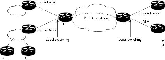
Incumbent local exchange carriers (ILECs) who use an interexchange carrier (IXC) to carry traffic between two local exchange carriers can use the Layer 2 Local Switching feature. Telecom regulations require the ILECs to pay the IXCs to carry that traffic. At times, the ILECs cannot terminate customer connections that are in different local access and transport areas (LATAs). In other cases, customer connections terminate in the same LATA, which may also be on the same router.
For example, company A has more than 50 LATAs across the country and uses three routers for each LATA. Company A uses companies B and C to carry traffic between local exchange carriers. Local switching of Layer 2 frames on the same router might be required.
Similarly, if a router is using, for example, a channelized interface, it might need to switch incoming and outgoing traffic across two logical interfaces that reside on a single physical port. The same-port local switching feature addresses that implementation.
Figure 1 shows a network that uses local switching for both Frame Relay to Frame Relay and ATM to Frame Relay local switching.
Figure 1 Local Switching Example
How to Configure Layer 2 Local Switching
The following sections explain the tasks you can perform to configure the Layer 2 Local Switching feature:
•
•
•
•
•
•
•
•
•
•
•
For information about Layer 2 Local Switching on the Cisco 10000 series routers, see the "Configuring Layer 2 Local Switching " section of the Cisco 10000 Series Router Broadband Aggregation, Leased-Line, and MPLS Configuration Guide at the following URL:
http://www.cisco.com/univercd/cc/td/doc/product/aggr/10000/swconfig/cfggdes/bba/localsw.htm
Configuring ATM-to-ATM PVC Local Switching and Same-Port Switching
You can configure local switching for both ATM AAL5 and ATM AAL0 encapsulation types.
Creating the ATM PVC is not required. If you do not create a PVC, one is created for you. For ATM-to-ATM local switching, the autoprovisioned PVC is given the default encapsulation type AAL0 cell relay.
Note
Use the following steps to configure ATM-to-ATM PVC local switching and same-port switching.
SUMMARY STEPS
1.
2.
3.
4.
5.
6.
7.
8.
DETAILED STEPS
Configuring ATM-to-ATM PVP Local Switching
Use the following steps to configure ATM-to-ATM PVP local switching.
Starting with Cisco IOS Release 12.0(30)S, you can configure same-port switching, as detailed in the "Configuring ATM PVP Same-Port Switching" section.
SUMMARY STEPS
1.
2.
3.
4.
5.
6.
7.
DETAILED STEPS
Configuring ATM PVP Same-Port Switching
Use the following steps to configure ATM PVP switching on a single ATM interface.
SUMMARY STEPS
1.
2.
3.
4.
5.
6.
7.
DETAILED STEPS
Configuring ATM-to-Ethernet Port Mode Local Switching
For ATM to Ethernet Port mode local switching, creating the ATM PVC is not required. If you do not create a PVC, one is created for you. For ATM-to-Ethernet local switching, the autoprovisioned PVC is given the default encapsulation type AAL5SNAP.
ATM-to-Ethernet local switching supports both the IP and Ethernet interworking types.
ATM-to-Ethernet local switching supports the following encapsulation types:
•
•
Use the following steps to configure local switching between ATM and Ethernet port mode.
SUMMARY STEPS
1.
2.
3.
4.
5.
6.
7.
8.
9.
10.
DETAILED STEPS
Configuring ATM-to-Ethernet VLAN Mode Local Switching
For ATM-to-Ethernet VLAN Mode local switching, creating the ATM PVC is not required. If you do not create a PVC, one is created for you. For ATM-to-Ethernet local switching, the autoprovisioned PVC is given the default encapsulation type AAL5SNAP.
ATM-to-Ethernet local switching supports both the IP and Ethernet interworking types.
ATM-to-Ethernet local switching supports the following encapsulation types:
•
•
The VLAN header is removed from frames that are received on an Ethernet subinterface.
Use the following steps to configure local switching for ATM to Ethernet in VLAN mode.
SUMMARY STEPS
1.
2.
3.
4.
5.
6.
7.
8.
9.
10.
DETAILED STEPS
Configuring Ethernet VLAN Same-Port Switching
Use the following steps to configure switching from one VLAN to another VLAN on the same Ethernet port.
SUMMARY STEPS
1.
2.
3.
4.
5.
6.
7.
8.
9.
DETAILED STEPS
Configuring Ethernet Port Mode to Ethernet VLAN Local Switching
This section explains how to configure local switching for Ethernet (port mode) to Ethernet VLAN.
SUMMARY STEPS
1.
2.
3.
4.
5.
6.
7.
DETAILED STEPS
Configuring ATM-to-Frame Relay Local Switching
You use the interworking ip keywords for configuring ATM-to-Frame Relay local switching.
FRF.8 Frame Relay-to-ATM service interworking functionality is not supported. Frame Relay discard-eligible (DE) bits do not get mapped to ATM cell loss priority (CLP) bits, and forward explicit congestion notification (FECN) bits do not get mapped to ATM explicit forward congestion indication (EFCI) bits.
For additional information about ATM-to-Frame Relay Local Switching, see the "Configuring Frame Relay-ATM Interworking" section of the Cisco IOS Wide Area Networking Configuration Guide.
Creating the PVC is not required. If you do not create a PVC, one is created for you. For ATM-to-Ethernet local switching, the automatically provisioned PVC is given the default encapsulation type AAL5SNAP.
ATM-to-Frame Relay local switching supports the following encapsulation types:
•
•
SUMMARY STEPS
1.
2.
3.
4.
5.
6.
7.
8.
9.
10.
11.
DETAILED STEPS
Configuring Frame Relay-to-Frame Relay Local Switching
For background information about Frame Relay-to-Frame Relay Local Switching, see the Distributed Frame Relay Switching feature module.
With Cisco IOS Release 12.0(30)S, you can switch between virtual circuits on the same port, as detailed in the "Configuring Frame Relay Same-Port Switching" section.
SUMMARY STEPS
1.
2.
3.
4.
5.
6.
7.
8.
9.
10.
DETAILED STEPS
Configuring Frame Relay Same-Port Switching
Use the following steps to configure local Frame Relay switching on a single interface.
SUMMARY STEPS
1.
2.
3.
4.
5.
6.
7.
8.
9.
10.
11.
DETAILED STEPS
Verifying Layer 2 Local Switching
This section provides the following verification tasks and troubleshooting information:
•
•
Verifying Layer 2 Local Switching Configuration
To verify configuration of the Layer 2 Local Switching feature, use the following commands on the provider edge (PE) router:
SUMMARY STEPS
1.
2.
3.
DETAILED STEPS
Step 1
The show connection command displays the local connection between an ATM interface and a Fast Ethernet interface:
Router# show connection name atm-eth-conID Name Segment 1 Segment 2 State==================================================================1 atm-eth-con ATM0/0/0 AAL5 0/100 FastEthernet6/0/0 UPThis example displays the local connection between an ATM interface and a serial interface:
Router# show connection name atm-fr-conID Name Segment 1 Segment 2 State==================================================================1 atm-fr-con ATM0/0/0 AAL5 0/100 Serial1/0/0 16 UPThis example displays a same-port connection on a serial interface.
Router# show connection name same-portID Name Segment 1 Segment 2 State==================================================================1 same-port Serial1/1/1 101 Serial1/1/1 102 UPStep 2
The show atm pvc command shows that interface ATM3/0 is UP:
Router# show atm pvcVCD/ Peak Avg/Min BurstInterface Name VPI VCI Type Encaps SC Kbps Kbps Cells Sts3/0 10 1 32 PVC FRATMSRV UBR 155000 UPStep 3
The show frame-relay pvc command shows a switched Frame Relay PVC:
Router# show frame-relay pvc 16PVC Statistics for interface POS5/0 (Frame Relay NNI)DLCI = 16, DLCI USAGE = SWITCHED, PVC STATUS = UP, INTERFACE = POS5/0LOCAL PVC STATUS = UP, NNI PVC STATUS = ACTIVEinput pkts 0 output pkts 0 in bytes 0out bytes 0 dropped pkts 100 in FECN pkts 0in BECN pkts 0 out FECN pkts 0 out BECN pkts 0in DE pkts 0 out DE pkts 0out bcast pkts 0 out bcast bytes 0switched pkts 0Detailed packet drop counters:no out intf 0 out intf down 100 no out PVC 0in PVC down 0 out PVC down 0 pkt too big 0pvc create time 00:25:32, last time pvc status changed 00:06:31
Verifying the NSF/SSO Local Switching Configuration
Layer 2 local switching provides NSF/SSO support for Local Switching of the following attachment circuits on the same router:
•
•
For information about configuring NSF/SSO on the Route Processors, see the Stateful Switchover feature module. To verify that the NSF/SSO: Layer 2 Local Switching is working correctly, follow the steps in this section.
SUMMARY STEPS
1.
2.
3.
4.
DETAILED STEPS
Step 1
Step 2
Step 3
Router# show connect allID Name Segment 1 Segment 2 State2 Eth-Vlan1 Fa1/1/1 Fa6/0/0/0.1 UPStep 4
Troubleshooting Tips
You can troubleshoot Layer 2 local switching using the following commands on the PE router:
•
•
•
•
•
•
Configuration Examples for Layer 2 Local Switching
This section provides the following configuration examples:
•
•
•
•
•
•
•
•
•
ATM-to-ATM Local Switching: Example
The following example shows local switching on ATM interfaces configured for AAL5:
interface atm1/0/0pvc 0/100 l2transportencapsulation aal5interface atm2/0/0pvc 0/100 l2transportencapsulation aal5connect aal5-conn atm1/0/0 0/100 atm2/0/0 0/100ATM PVC Same-Port Switching: Example
The following example shows same-port switching between two PVCs on one ATM interface:
interface atm1/0/0pvc 0/100 l2transportencapsulation aal5pvc 0/200 l2transportencapsulation aal5connect conn atm1/0/0 0/100 atm1/0/0 0/200ATM PVP Same-Port Switching: Example
The following example shows same-port switching between two PVPs on one ATM interface:
interface atm1/0/0atm pvp 100 l2transportatm pvp 200 l2transportconnect conn atm1/0/0 100 atm1/0/0 200ATM-to-Ethernet Local Switching: Examples
ATM-to-Ethernet local switching terminates an ATM frame to an Ethernet/VLAN frame over the same PE router. Two interworking models are used: Ethernet mode and IP mode.
ATM to Ethernet VLAN: Example
The following example shows an Ethernet interface configured for Ethernet VLAN, and an ATM PVC interface configured for AAL5 encapsulation. The connect command allows local switching between these two interfaces and specifies the interworking type as Ethernet mode.
interface fastethernet6/0/0.1encapsulation dot1q 10interface atm2/0/0pvc 0/400 l2transportencapsulation aal5connect atm-ethvlan-con atm2/0/0 0/400 fastethernet6/0/0.1 interworking ethernetATM to Ethernet Port Mode: Example
The following example shows an Ethernet interface configured for Ethernet and an ATM interface configured for AAL5SNAP encapsulation. The connect command allows local switching between these two interfaces and specifies the interworking type as IP mode.
interface atm0/0/0pvc 0/100 l2transportencapsulation aal5snapinterface fastethernet6/0/0connect atm-eth-con atm0/0/0 0/100 fastethernet6/0/0 interworking ipEthernet VLAN Same-Port Switching: Example
The following example shows same-port switching between two VLANs on one Ethernet interface:
interface fastethernet0/0.1encapsulation dot1q 1interface fastethernet0/0.2encapsulation dot1q 2connect conn FastEthernet0/0.1 FastEthernet0/0.2ATM-to-Frame Relay Local Switching: Example
The following example shows a serial interface configured for Frame Relay and an ATM interface configured for AAL5SNAP encapsulation. The connect command allows local switching between these two interfaces.
interface serial1/0encapsulation frame-relayinterface atm1/0pvc 7/100 l2transportencapsulation aal5snapconnect atm-fr-conn atm1/0 7/100 serial1/0 100 interworking ipFrame Relay-to-Frame Relay Local Switching: Example
The following example shows serial interfaces configured for Frame Relay. The connect command allows local switching between these two interfaces.
frame-relay switchingip cef distributedinterface serial3/0/0encapsulation frame-relayframe-relay interface-dlci 100 switchedframe-relay intf-type dceinterface serial3/1/0encapsulation frame-relay ietfframe-relay interface-dlci 200 switchedframe-relay intf-type dceconnect fr-con serial3/0/0 100 serial3/1/0 200Frame Relay DLCI Same-Port Switching: Example
The following example shows same-port switching between two data links on one Frame Relay interface:
interface serial1/0encapsulation frame-relayframe-relay int-type nniconnect conn serial1/0 100 serial1/0 200NSF/SSO: Ethernet Port Mode to Ethernet VLAN Local Switching: Example
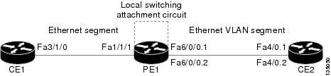
The following configuration uses the network topology shown in Figure 2.
Figure 2 NSF/SSO: Layer 2 Local Switching: Ethernet to Ethernet VLAN
The following example shows the configuration of the the CE interfaces to connect to the PE1 router:
The following example shows the configuration of the PE1 router with NSF/SSO and the PE interfaces to the CE routers:
The following example shows the configuration of ICMP Router Discovery Protocol (IRDP) on the CE router for Interworking IP for ARP mediation:
interface FastEthernet3/1/0
ip irdp
ip irdp maxadvertinterval 0
interface FastEthernet4/0.1
ip irdp
ip irdp maxadvertinterval 0
The following example shows the configuration of OSPF on the CE routers:
The following example shows the configuration of local switching on the PE1 router for interworking Ethernet:
connect eth-vlan1 fa1/1/1 fa6/0/0.1 interworking ethernet
connect eth-vlan2 fa4/0/0 fa6/0/0.2 interworking ethernet
The following example shows the configuration of local switching on the PE1 router for interworking IP:
connect eth-vlan1 fa1/1/1 fa6/0/0.1 interworking ip
connect eth-vlan2 fa4/0/0 fa6/0/0.2 interworking ip
Additional References
The following sections provide references related to the Layer 2 Local Switching feature.
Related Documents
High availability for Any Transport over MPLS
L2VPN interworking
Frame Relay-to-ATM interworking
Frame Relay-to-Frame Relay local switching
Layer 2 Tunnel Protocol Version 3
Any Transport over MPLS
Layer 2 Local Switching for the Cisco 10000 series router
Cisco 10000 Series Router Broadband Aggregation, Leased-Line, and MPLS Configuration Guide
Standards
MIBs
RFCs
Technical Assistance
Command Reference
This section documents new and modified commands only.
•
•
connect (L2VPN local switching)
To create Layer 2 data connections between two ports on the same router, use the connect command in global configuration mode. To remove such connections, use the no form of this command.
connect connection-name interface [dlci | pvc | pvp] interface [dlci | pvc | pvp] [interworking ip | ethernet]
no connect connection-name interface [dlci | pvc | pvp] interface [dlci | pvc | pvp] [interworking ip | ethernet]
Syntax Description
Command Default
No default behavior or values
Command Modes
Global configuration
Command History
Examples
The following example shows an Ethernet interface configured for Ethernet, plus an ATM interface configured for AAL5SNAP encapsulation. The connect command allows local switching between these two interfaces and specifies the interworking type as IP mode.
Router(config)# interface atm0/0/0Router(config-if)# pvc 0/100 l2transportRouter(cfg-if-atm-l2trans-pvc)# encapsulation aal5snapRouter(config)# interface fastethernet6/0/0.1Router(config-subif)# encapsulation dot1q 100Router(config)# connect atm-eth-con atm0/0/0 0/100 fastethernet6/0/0.1 interworking ipRelated Commands
encapsulation (Layer 2 local switching)
To configure the ATM adaptation layer (AAL) for a Layer 2 local switching ATM permanent virtual circuit (PVC), use the encapsulation command in ATM PVC L2transport configuration mode. To remove an encapsulation from a PVC, use the no form of this command.
encapsulation layer-type
no encapsulation layer-type
Syntax Description
layer-type
Adaptation layer type. The values are:
•
•
•
•
•
Command Default
If you do not create a PVC, one is created for you. The default encapsulation types for autoprovisioned PVCs are as follows:
•
•
Command Modes
ATM PVC L2transport configuration
Command History
Usage Guidelines
The pvc command and the encapsulation command work together. The use of these commands with Layer 2 local switching is slightly different from the use of these commands with other applications. The following list highlights the differences:
•
•
Table 1 shows the encapsulation types supported for each transport type:
Examples
The following example shows how to configure a PVC to transport AAL0 packets for Layer 2 local switching:
pvc 1/100 l2transportencapsulation aal0Related Commands
show connection
To display the status of interworking connections, use the show connection command in privileged EXEC mode.
show connection [all | element | id ID | name name | port port]
Syntax Description
Command Modes
Privileged EXEC
Command History
Examples
The following example shows the local interworking connections on a router:
Router# show connectionID Name Segment 1 Segment 2 State========================================================================1 conn1 ATM 1/0/0 AAL5 0/100 ATM 2/0/0 AAL5 0/100 UP2 conn2 ATM 2/0/0 AAL5 0/300 Serial0/1 16 UP3 conn3 ATM 2/0/0 AAL5 0/400 FA 0/0.1 10 UP4 conn4 ATM 1/0/0 CELL 0/500 ATM 2/0/0 CELL 0/500 UP5 conn5 ATM 1/0/0 CELL 100 ATM 2/0/0 CELL 100 UPTable 1 describes the significant fields shown in the display.
Related Commands
Feature Information for Layer 2 Local Switching
Table 3 lists the release history for this feature.
Not all commands may be available in your Cisco IOS software release. For release information about a specific command, see the command reference documentation.
Cisco IOS software images are specific to a Cisco IOS software release, a feature set, and a platform. Use Cisco Feature Navigator to find information about platform support and Cisco IOS software image support. Access Cisco Feature Navigator at http://www.cisco.com/go/fn. You must have an account on Cisco.com. If you do not have an account or have forgotten your username or password, click Cancel at the login dialog box and follow the instructions that appear.
Note
Table 3 Feature Information for Layer 2 Local Switching
Layer 2 Local Switching
12.0(27)S
12.2(25)S
12.0(30)S
12.0(31)S2
12.0(32)SY
12.2(28)SB
12.4(11)T
12.2(33)SRB
12.2(33)SXHThe Layer 2 Local Switching feature allows you to switch Layer 2 data between two interfaces on the same router, and in some cases to switch Layer 2 data between two circuits on the same interface port.
The feature was introduced in Cisco IOS Release 12.0(27)S on the Cisco 7200 and 7500 series routers.
The feature was integrated into Cisco IOS Release 12.2(25)S.
In Cisco IOS Release 12.0(30)S, support for same-port switching was added. Support for Layer 2 interface-to-interface local switching was added on the Cisco 12000 series router.
In Cisco IOS Release 12.0(31)S2, support was added for customer-facing IP Service Engine (ISE) interfaces on the Cisco 12000 series router.
In Cisco IOS Release 12.0(32)SY, support was added for customer-facing interfaces on Engine 5 shared port adapters (SPAs) and SPA Interface Processors (SIPs) on the Cisco 12000 series router.
In Cisco IOS Release 12.2(28)SB, this feature was updated to include NSF/SSO support on the Cisco 7500 series routers for the following local switching types on nonstop forwarding/stateful switchover (NSF/SSO):
•
•
In Cisco IOS Release 12.4(11)T, support was added for the following local switching types:
•
•
•
•
In Cisco IOS Release 12.2(28)SB, for information about Layer 2 Local Switching on the Cisco 10000 series routers, see the "Configuring Layer 2 Local Switching" section of the Cisco 10000 Series Router Broadband Aggregation, Leased-Line, and MPLS Configuration Guide at the following URL:
http://www.cisco.com/univercd/cc/td/doc/product/aggr/10000/swconfig/cfggdes/bba/localsw.htm
In Cisco IOS Release 12.2(33)SXH, support was added for like-to-like Local Switching (that is, ATM to ATM, and FR to FR only) on 6500 series switches and 7600 series routers. Same-port switching was not added on those devices.
CCVP, the Cisco logo, and the Cisco Square Bridge logo are trademarks of Cisco Systems, Inc.; Changing the Way We Work, Live, Play, and Learn is a service mark of Cisco Systems, Inc.; and Access Registrar, Aironet, BPX, Catalyst, CCDA, CCDP, CCIE, CCIP, CCNA, CCNP, CCSP, Cisco, the Cisco Certified Internetwork Expert logo, Cisco IOS, Cisco Press, Cisco Systems, Cisco Systems Capital, the Cisco Systems logo, Cisco Unity, Enterprise/Solver, EtherChannel, EtherFast, EtherSwitch, Fast Step, Follow Me Browsing, FormShare, GigaDrive, HomeLink, Internet Quotient, IOS, iPhone, IP/TV, iQ Expertise, the iQ logo, iQ Net Readiness Scorecard, iQuick Study, LightStream, Linksys, MeetingPlace, MGX, Networking Academy, Network Registrar, Packet, PIX, ProConnect, ScriptShare, SMARTnet, StackWise, The Fastest Way to Increase Your Internet Quotient, and TransPath are registered trademarks of Cisco Systems, Inc. and/or its affiliates in the United States and certain other countries.
All other trademarks mentioned in this document or Website are the property of their respective owners. The use of the word partner does not imply a partnership relationship between Cisco and any other company. (0705R)
Any Internet Protocol (IP) addresses used in this document are not intended to be actual addresses. Any examples, command display output, and figures included in the document are shown for illustrative purposes only. Any use of actual IP addresses in illustrative content is unintentional and coincidental.
Copyright © 2003-2007 Cisco Systems, Inc. All rights reserved.