Downloads |
 Feedback Feedback
|
Table Of Contents
Prerequisites for Any Transport over MPLS
Restrictions for Any Transport over MPLS
Information About Any Transport over MPLS
How AToM Transports Layer 2 Packets
AToM Configuration Commands Prior to Cisco IOS Release 12.0(25)S
MPLS Traffic Engineering Fast Reroute
Maximum Transmission Unit Guidelines for Estimating Packet Size
Estimating Packet Size: Example
Frame Relay over MPLS and DTE, DCE, and NNI Connections
Local Management Interface and Frame Relay over MPLS
QoS Features Supported with AToM
How to Configure Any Transport over MPLS
Configuring the Pseudowire Class
Configuring ATM AAL5 over MPLS on PVCs
Configuring ATM AAL5 over MPLS in VC Class Configuration Mode
Configuring OAM Cell Emulation for ATM AAL5 over MPLS
Configuring OAM Cell Emulation for ATM AAL5 over MPLS on PVCs
Configuring OAM Cell Emulation for ATM AAL5 over MPLS in VC Class Configuration Mode
Configuring ATM Cell Relay over MPLS in VC Mode
Configuring ATM Cell Relay over MPLS in VC Mode Using VC Class Configuration Mode
Configuring ATM Cell Relay over MPLS in PVP Mode
Configuring ATM Cell Relay over MPLS in Port Mode
Configuring ATM Single Cell Relay over MPLS
Configuring ATM Packed Cell Relay over MPLS
Configuring ATM Packed Cell Relay over MPLS in VC Mode
Configuring ATM Packed Cell Relay over MPLS in VC Mode Using VC Class Configuration Mode
Configuring ATM Packed Cell Relay over MPLS in VP Mode
Configuring ATM Packed Cell Relay over MPLS in Port Mode
Configuring Ethernet over MPLS in VLAN Mode
Configuring Ethernet over MPLS in Port Mode
Configuring Ethernet over MPLS with VLAN ID Rewrite
Configuring Ethernet over MPLS with MTU Values in xconnect Configuration Mode
Configuring Frame Relay over MPLS with DLCI-to-DLCI Connections
Configuring Frame Relay over MPLS with Port-to-Port Connections
Configuring HDLC and PPP over MPLS
Setting Experimental Bits with AToM
Setting the Frame Relay Discard Eligibility Bit on the Cisco 7200 and 7500 Series Routers
Matching the Frame Relay DE Bit on the Cisco 7200 and 7500 Series Routers
Configuration Examples for Any Transport over MPLS
Ethernet over MPLS with MPLS Traffic Engineering Fast Reroute: Example
Configuring MTU Values in xconnect Configuration Mode for AToM: Example
Configuring MTU Values in xconnect Configuration Mode for L2VPN Interworking: Example
encapsulation (Any Transport over MPLS)
Feature Information for Any Transport over MPLS
Any Transport over MPLS
First Published: January 1, 2001Last Updated: July 13, 2007Any Transport over MPLS (AToM) transports data link layer (Layer 2) packets over a Multiprotocol Label Switching (MPLS) backbone. AToM enables service providers to connect customer sites with existing Layer 2 networks by using a single, integrated, packet-based network infrastructure—a Cisco MPLS network. Instead of using separate networks with network management environments, service providers can deliver Layer 2 connections over an MPLS backbone. AToM provides a common framework to encapsulate and transport supported Layer 2 traffic types over an MPLS network core.
AToM supports the following like-to-like transport types:
•
ATM Adaptation Layer Type-5 (AAL5) over MPLS
•
•
•
•
•
Finding Feature Information in This Module
Your Cisco IOS software release may not support all of the features documented in this module. To reach links to specific feature documentation in this module and to see a list of the releases in which each feature is supported, use the "Feature Information for Any Transport over MPLS" section.
Finding Support Information for Platforms and Cisco IOS and Catalyst OS Software Images
Use Cisco Feature Navigator to find information about platform support and Cisco IOS and Catalyst OS software image support. To access Cisco Feature Navigator, go to http://www.cisco.com/go/cfn. An account on Cisco.com is not required.
Contents
•
•
•
•
•
•
Prerequisites for Any Transport over MPLS
Before configuring AToM, ensure that the network is configured as follows:
•
•
•
•
•
–
–
•
–
–
•
–
–
–
–
–
–
•
•
•
Restrictions for Any Transport over MPLS
The following general restrictions pertain to all transport types under AToM:
•
•
•
•
The following restrictions pertain to ATM Cell Relay over MPLS:
•
•
In Cisco IOS Release 12.0(25)S, when you configured the Cisco 12000 series 8-port OC-3 STM-1 ATM line card for ATM Cell Relay over MPLS, two ports were reserved. That is no longer true. Only one port is reserved now.
In addition, in Cisco IOS Release 12.0(25)S, if you configured an 8-port OC-3 STM-1 ATM port for ATM AAL5 over MPLS and then configured ATM single cell relay over MPLS on that port, the VCs and VPs for AAL5 on the port and its corresponding port were removed. Starting in Cisco IOS Release 12.0(26)S, this behavior no longer occurs. ATM AAL5 over MPLS and ATM single cell relay over MPLS are supported on the same port. The Cisco 12000 series 8-port OC-3 STM-1 ATM line cards now support, by default, the ATM single cell relay over MPLS feature in both VP and VC modes and ATM AAL5 over MPLS on the same port.
•
The following restrictions pertain to the Ethernet over MPLS feature:
•
•
•
•
Caution
If the interface MTU is greater than or equal to 1524 bytes, then you can set the maximum MPLS MTU as high as the interface MTU. For example, if the interface MTU is set to 1600 bytes, then you can set the MPLS MTU to a maximum of 1600 bytes. If you set the MPLS MTU higher than the interface MTU, traffic is dropped.
For interfaces that do not allow you to configure the interface MTU value and the interface MTU is 1500 bytes, the MPLS MTU range is 64 to 1524 bytes.
If you upgrade to Cisco IOS Release 12.2(25)S from an earlier release and you have an MPLS MTU setting that does not conform to these guidelines, the command is rejected. See the "Maximum Transmission Unit Guidelines for Estimating Packet Size" section for more information.
The following restrictions pertain to the Frame Relay over MPLS feature:
•
•
Information About Any Transport over MPLS
To configure AToM, you must understand the following concepts:
•
•
•
•
•
•
How AToM Transports Layer 2 Packets
AToM encapsulates Layer 2 frames at the ingress PE and sends them to a corresponding PE at the other end of a pseudowire, which is a connection between the two PE routers. The egress PE removes the encapsulation and sends out the Layer 2 frame.
The successful transmission of the Layer 2 frames between PE routers is due to the configuration of the PE routers. You set up the connection, called a pseudowire, between the routers. You specify the following information on each PE router:
•
•
•
The following example shows the basic configuration steps on a PE router that enable the transport of Layer 2 packets. Each transport type has slightly different steps.
Step 1 defines the interface or subinterface on the PE router:
Router# interface interface-type interface-numberStep 2 specifies the encapsulation type for the interface, such as dot1q:
Router(config-if)# encapsulation encapsulation-typeStep 3 does the following:
•
•
The combination of the peer router ID and the VC ID must be unique on the router. Two circuits cannot use the same combination of peer router ID and VC ID.
•
Router(config-if)# xconnect peer-router-id vcid encapsulation mplsAs an alternative, you can set up a pseudowire class to specify the tunneling method and other characteristics. See the "Configuring the Pseudowire Class" section for more information.
AToM Configuration Commands Prior to Cisco IOS Release 12.0(25)S
In releases of AToM previous to Cisco IOS 12.0(25)S, the command used to configure AToM circuits was mpls l2 transport route. This command has been replaced with the xconnect command.
No enhancements will be made to the mpls l2transport route command. Enhancements will be made to either the xconnect command or pseudowire-class command. Therefore, Cisco recommends that you use the xconnect command to configure AToM circuits.
Configurations from releases previous to Cisco IOS 12.0(25)S that use the mpls l2transport route command are still supported.
Benefits of AToM
The following list explains some of the benefits of enabling Layer 2 packets to be sent in the MPLS network:
•
•
•
MPLS Traffic Engineering Fast Reroute
AToM can use MPLS traffic engineering (TE) tunnels with fast reroute (FRR) support. AToM VCs can be rerouted around a failed link or node at the same time as MPLS and IP prefixes.
Enabling fast reroute on AToM does not require any special commands; you can use standard fast reroute commands. At the ingress PE, an AToM tunnel is protected by fast reroute when it is routed to an FRR-protected TE tunnel. Both link and node protection are supported for AToM VCs at the ingress PE. For more information on configuring MPLS TE fast reroute, see the following document:
MPLS Traffic Engineering (TE)—Link and Node Protection, with RSVP Hellos Support
Note
For the Cisco 12000 series routers, fast reroute uses three or more labels, depending on where the TE tunnel ends:
•
•
Engine 0 ATM line cards support three or more labels, although performance degrades. Engine 2 Gigabit Ethernet line cards and engine 3 line cards support three or more labels and can work with the fast reroute feature.
You can issue the debug mpls l2transport fast-reroute command to debug fast reroute with AToM.
Note
Cisco 12000 series line cards. This command does not display output for the Cisco 7500 (both Route Processor (RP) and VIP) series routers, Cisco 7200 series routers, and Cisco 12000 series RP.In the following example, the primary link is disabled, which causes the backup tunnel (Tunnel 1) to become the primary path. In the following example, bolded output show the status of the tunnel:
Router# execute-on slot 3 debug mpls l2transport fast-reroute========= Line Card (Slot 3) =========AToM fast reroute debugging is onSLOT 3:Sep 16 17:58:56.346: AToM SMGR: Processing TFIB FRR event for 10.4.0.1SLOT 3:Sep 16 17:58:56.346: AToM SMGR: Finished processing TFIB FRR event for 10.4.0.1SLOT 3:Sep 16 17:58:56.346: AToM SMGR: Processing TFIB FRR event for Tunnel41SLOT 3:Sep 16 17:58:56.346: AToM SMGR: Finished processing TFIB FRR event for Tunnel41Sep 16 17:58:58.342: %LINK-3-UPDOWN: Interface POS0/0, changed state to downSep 16 17:58:58.342: %OSPF-5-ADJCHG: Process 1, Nbr 10.0.0.1 on POS0/0 from FULL to DOWN, Neighbor Down: Interface down or detachedSep 16 17:58:59.342: %LINEPROTO-5-UPDOWN: Line protocol on Interface POS0/0, changed state to downMaximum Transmission Unit Guidelines for Estimating Packet Size
The following calculation helps you determine the size of the packets traveling through the core network. You set the maximum transmission unit (MTU) on the core-facing interfaces of the P and PE routers to accommodate packets of this size. The MTU should be greater than or equal to the total bytes of the items in the following equation:
Core MTU >= (Edge MTU + Transport header + AToM header + (MPLS label stack * MPLS label size))
The following sections describe the variables used in the equation.
Edge MTU
The edge MTU is the MTU for the customer-facing interfaces.
Transport Header
The Transport header depends on the transport type. Table 1 lists the specific sizes of the headers.
AToM Header
The AToM header is 4 bytes (control word). The control word is optional for Ethernet, PPP, HDLC, and cell relay transport types. However, the control word is required for Frame Relay and ATM AAL5 transport types.
MPLS Label Stack
The MPLS label stack size depends on the configuration of the core MPLS network:
•
•
•
•
•
•
•
Other circumstances can increase the MPLS label stack size. Therefore, analyze the complete data path between the AToM tunnel endpoints and determine the maximum MPLS label stack size for your network. Then multiply the label stack size by the size of the MPLS label.
Estimating Packet Size: Example
Thee size of packets is estimate in the following example, which uses the following assumptions:
•
•
•
•
Edge MTU + Transport header + AToM header + (MPLS label stack * MPLS label) = Core MTU1500 + 18 + 0 + (2 * 4 ) = 1526You must configure the P and PE routers in the core to accept packets of 1526 bytes.
Once you determine the MTU size to set on your P and PE routers, you can issue the mtu command on the routers to set the MTU size. The following example specifies an MTU of 1526 bytes:
Router(config-if)# mtu 1526mpls mtu Command Changes
Some interfaces (such as FastEthernet) require the mpls mtu command to change the MTU size.
In Cisco IOS Release 12.2(25)S, the behavior of the mpls mtu command changed.If the interface MTU is ferwer than 1524 bytes, you can set the maximum MPLS MTU to 24 bytes more than the interface MTU. For example, if the interface MTU is set to 1510 bytes, then you can set the maximum MPLS MTU to 1534 bytes (1510 + 24).
Caution
If the interface MTU is greater than or equal to 1524 bytes, then you can set the maximum MPLS MTU as high as the interface MTU. For example, if the interface MTU is set to 1600 bytes, then you can set the MPLS MTU to a maximum of 1600 bytes. If you set the MPLS MTU higher than the interface MTU, traffic is dropped.
For interfaces that do not allow you to configure the interface MTU value and the interface MTU is
1500 bytes, the MPLS MTU range is 64 to 1524 bytes.If you upgrade to Cisco IOS Release 12.2(25)S and you have an MPLS MTU setting that does not conform to these guidelines, the command is rejected.
For Cisco IOS Release 12.2(27)SBC, 12.2(33)SRA, 12.4(11)T, 12.2(33)SXH, and later releases, you cannot set the MPLS MTU greater than the interface MTU. This eliminates problems, such as dropped packets, data corruption, and high CPU rates. See the MPLS MTU Command Changes document for more information.
Frame Relay over MPLS and DTE, DCE, and NNI Connections
You can configure an interface as a DTE device or a DCE switch, or as a switch connected to a switch with network-to-network interface (NNI) connections. Use the following command in interface configuration mode:
frame-relay intf-type [dce | dte | nni]
The keywords are explained in Table 2.
Local Management Interface and Frame Relay over MPLS
Local Management Interface (LMI) is a protocol that communicates status information about PVCs. When a PVC is added, deleted, or changed, the LMI notifies the endpoint of the status change. LMI also provides a polling mechanism that verifies that a link is up.
How LMI Works
To determine the PVC status, LMI checks that a PVC is available from the reporting device to the Frame Relay end-user device. If a PVC is available, LMI reports that the status is "Active," which means that all interfaces, line protocols, and core segments are operational between the reporting device and the Frame Relay end-user device. If any of those components is not available, the LMI reports a status of "Inactive."
Note
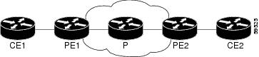
Figure 1 is a sample topology that helps illustrate how LMI works.
Figure 1 Sample Topology
In Figure 1, note the following:
•
•
•
•
The LMI protocol behavior depends on whether you have DLCI-to-DLCI or port-to-port connections.
DLCI-to-DLCI Connections
If you have DLCI-to-DLCI connections, LMI runs locally on the Frame Relay ports between the PE and CE devices:
•
•
–
–
–
For DTE or DCE configurations, the following LMI behavior exists: The Frame Relay device accessing the network (DTE) does not report PVC status. Only the network device (DCE) or NNI can report status. Therefore, if a problem exists on the DTE side, the DCE is not aware of the problem.
Port-to-Port Connections
If you have port-to-port connections, the PE routers do not participate in the LMI status-checking procedures. LMI operates between the CE routers only. The CE routers must be configured as DCE-DTE or NNI-NNI.
For information about LMI, including configuration instructions, see the "Configuring the LMI" section of the Configuring Frame Relay document.
QoS Features Supported with AToM
For information about configuring QoS features on the Cisco 12000 series routers, see the following feature module:
Any Transport over MPLS (AToM): Layer 2 QoS for the Cisco 12000 Series Router (Quality of Service)
The following tables list the QoS features supported by AToM on the Cisco 7200 and 7500 series routers:
•
•
•
How to Configure Any Transport over MPLS
This section explains how to perform a basic AToM configuration and includes the following procedures:
•
•
•
•
•
•
•
•
•
•
•
•
•
•
•
•
•
•
•
•
•
•
•
Configuring the Pseudowire Class
The successful transmission of the Layer 2 frames between PE routers is due to the configuration of the PE routers. You set up the connection, called a pseudowire, between the routers.
Note
The pseudowire-class configuration group specifies the following characteristics of the tunneling mechanism:
•
•
•
For more information about the pseudowire-class command, see the following feature module:
Layer 2 Tunnel Protocol Version 3
You must specify the encapsulation mpls command as part of the pseudowire class or as part of the xconnect command for the AToM VCs to work properly. If you omit the encapsulation mpls command as part of the xconnect command, you receive the following error:
% Incomplete command.Once you specify the encapsulation mpls command, you cannot remove it using the no encapsulation mpls command. Nor can you change the command's setting using the encapsulation l2tpv3 command. Those methods result in the following error message:
Encapsulation changes are not allowed on an existing pw-class.To remove the command, you must delete the pseudowire with the no pseudowire-class command. To change the type of encapsulation, remove the pseudowire with the no pseudowire-class command and reestablish the pseudowire and specify the new encapsulation type.
SUMMARY STEPS
1.
2.
3.
4.
DETAILED STEPS
Configuring ATM AAL5 over MPLS on PVCs
ATM AAL5 over MPLS for permanent virtual circuits encapsulates ATM AAL5 service data unit (SDUs) in MPLS packets and forwards them across the MPLS network. Each ATM AAL5 SDU is transported as a single packet.
Restrictions
AAL5 over MPLS is supported only in SDU mode.
SUMMARY STEPS
1.
2.
3.
4.
5.
6.
7.
8.
9.
10.
DETAILED STEPS
Examples
The following example enables ATM AAL5 over MPLS on an ATM PVC:
enableconfigure terminalinterface atm1/0pvc 1/200 l2transportencapsulation aal5xconnect 10.13.13.13 100 encapsulation mplsThe following is example output from the show mpls l2transport vc, which shows that ATM AAL5 over MPLS is configured on a PVC:
Router# show mpls l2transport vcLocal intf Local circuit Dest address VC ID Status--------- ------------- ------------ ----- ------ATM1/0 ATM AAL5 1/100 10.4.4.4 100 UPConfiguring ATM AAL5 over MPLS in VC Class Configuration Mode
You can create a VC class that specifies the AAL5 encapsulation and then attach the encapsulation type to an interface, subinterface, or PVC. The following task creates a VC class and attaches it to a main interface.
Restriction
AAL5 over MPLS is supported only in SDU mode.
SUMMARY STEPS
1.
2.
3.
4.
5.
6.
7.
8.
9.
10.
11.
12.
13.
DETAILED STEPS
Examples
The following example configures ATM AAL5 over MPLS in VC class configuration mode. The VC class is then applied to an interface.
enableconfigure terminalvc-class atm aal5classencapsulation aal5interface atm1/0class-int aal5classpvc 1/200 l2transportxconnect 10.13.13.13 100 encapsulation mplsThe following example configures ATM AAL5 over MPLS in VC class configuration mode. The VC class is then applied to a PVC.
enableconfigure terminalvc-class atm aal5classencapsulation aal5interface atm1/0pvc 1/200 l2transportclass-vc aal5classxconnect 10.13.13.13 100 encapsulation mplsIn the following example, the command output of the show atm class-links command verifies that ATM AAL5 over MPLS is configured as part of a VC class. The command output shows the type of encapsulation and that the VC class was applied to an interface.
Router# show atm class-links 1/100Displaying vc-class inheritance for ATM1/0.0, vc 1/100:no broadcast - Not configured - using defaultencapsulation aal5 - VC-class configured on main interfaceConfiguring OAM Cell Emulation for ATM AAL5 over MPLS
If a PE router does not support the transport of Operation, Administration, and Maintenance (OAM) cells across a label switched path (LSP), you can use OAM cell emulation to locally terminate or loop back the OAM cells. You configure OAM cell emulation on both PE routers, which emulates a VC by forming two unidirectional LSPs. You use the oam-ac emulation-enable and oam-pvc manage commands on both PE routers to enable OAM cell emulation.
After you enable OAM cell emulation on a router, you can configure and manage the ATM VC in the same manner as you would a terminated VC. A VC that has been configured with OAM cell emulation can send loopback cells at configured intervals toward the local CE router. The endpoint can be either of the following:
•
•
The OAM cells include the following cells:
•
•
These cells identify and report defects along a VC. When a physical link or interface failure occurs, intermediate nodes insert OAM AIS cells into all the downstream devices affected by the failure. When a router receives an AIS cell, it marks the ATM VC down and sends an RDI cell to let the remote end know about the failure.
This section contains two tasks:
•
•
Configuring OAM Cell Emulation for ATM AAL5 over MPLS on PVCs
Perform this task to configure OAM cell emulation for ATM AAL5 over MPLS on a PVC.
Note
SUMMARY STEPS
1.
2.
3.
4.
5.
6.
7.
8.
9.
10.
11.
12.
DETAILED STEPS
Examples
The following example enables OAM cell emulation on an ATM PVC:
interface ATM 1/0/0pvc 1/200 l2transportencapsulation aal5xconnect 10.13.13.13 100 encapsulation mplsoam-ac emulation-enableoam-pvc manageThe following example sets the rate at which an AIS cell is sent every 30 seconds:
interface ATM 1/0/0pvc 1/200 l2transportencapsulation aal5xconnect 10.13.13.13 100 encapsulation mplsoam-ac emulation-enable 30oam-pvc manageThe output of the show atm pvc command in the following example shows that OAM cell emulation is enabled on the ATM PVC:
Router# show atm pvc 5/500ATM4/1/0.200: VCD: 6, VPI: 5, VCI: 500UBR, PeakRate: 1AAL5-LLC/SNAP, etype:0x0, Flags: 0x34000C20, VCmode: 0x0OAM Cell Emulation: enabled, F5 End2end AIS Xmit frequency: 1 second(s)OAM frequency: 0 second(s), OAM retry frequency: 1 second(s)OAM up retry count: 3, OAM down retry count: 5OAM Loopback status: OAM DisabledOAM VC state: Not ManagedVerifiedILMI VC state: Not ManagedInPkts: 564, OutPkts: 560, InBytes: 19792, OutBytes: 19680InPRoc: 0, OutPRoc: 0InFast: 4, OutFast: 0, InAS: 560, OutAS: 560InPktDrops: 0, OutPktDrops: 0CrcErrors: 0, SarTimeOuts: 0, OverSizedSDUs: 0Out CLP=1 Pkts: 0OAM cells received: 26F5 InEndloop: 0, F5 InSegloop: 0, F5 InAIS: 0, F5 InRDI: 26OAM cells sent: 77F5 OutEndloop: 0, F5 OutSegloop: 0, F5 OutAIS: 77, F5 OutRDI: 0OAM cell drops: 0Status: UPConfiguring OAM Cell Emulation for ATM AAL5 over MPLS in VC Class Configuration Mode
The following steps explain how to configure OAM cell emulation as part of a VC class. You can then apply the VC class to an interface, a subinterface, or a VC. When you configure OAM cell emulation in VC class configuration mode and then apply the VC class to an interface, the settings in the VC class apply to all the VCs on the interface, unless you specify a different OAM cell emulation value at a lower level, such as the subinterface or VC level. For example, you can create a VC class that specifies OAM cell emulation and sets the rate of AIS cells to every 30 seconds. You can apply the VC class to an interface. Then, for one PVC, you can enable OAM cell emulation and set the rate of AIS cells to every 15 seconds. All the PVCs on the interface use the cell rate of 30 seconds, except for the one PVC that was set to 15 seconds.
Perform this task to enable OAM cell emulation as part of a VC class and apply it to an interface.
Note
SUMMARY STEPS
1.
2.
3.
4.
5.
6.
7.
8.
9.
10.
11.
DETAILED STEPS
Examples
The following example configures OAM cell emulation for ATM AAL5 over MPLS in VC class configuration mode. The VC class is then applied to an interface.
enableconfigure terminalvc-class atm oamclassencapsulation aal5oam-ac emulation-enable 30oam-pvc manageinterface atm1/0class-int oamclasspvc 1/200 l2transportxconnect 10.13.13.13 100 encapsulation mplsThe following example configures OAM cell emulation for ATM AAL5 over MPLS in VC class configuration mode. The VC class is then applied to a PVC.
enableconfigure terminalvc-class atm oamclassencapsulation aal5oam-ac emulation-enable 30oam-pvc manageinterface atm1/0pvc 1/200 l2transportclass-vc oamclassxconnect 10.13.13.13 100 encapsulation mplsThe following example configures OAM cell emulation for ATM AAL5 over MPLS in VC class configuration mode. The VC class is then applied to an interface. One PVC is configured with OAM cell emulation at an AIS rate of 10. That PVC uses the AIS rate of 10 instead of 30.
enableconfigure terminalvc-class atm oamclassencapsulation aal5oam-ac emulation-enable 30oam-pvc manageinterface atm1/0class-int oamclasspvc 1/200 l2transportoam-ac emulation-enable 10xconnect 10.13.13.13 100 encapsulation mplsConfiguring ATM Cell Relay over MPLS in VC Mode
Perform this task to configure ATM cell relay on the permanent virtual circuits.
SUMMARY STEPS
1.
2.
3.
4.
5.
6.
7.
8.
9.
10.
DETAILED STEPS
Example
The output of the following show atm vc command shows that the interface is configured for VC mode cell relay:
Router# show atm vc 7ATM3/0: VCD: 7, VPI: 23, VCI: 100UBR, PeakRate: 149760AAL0-Cell Relay, etype:0x10, Flags: 0x10000C2D, VCmode: 0x0OAM Cell Emulation: not configuredInBytes: 0, OutBytes: 0Status: UPConfiguring ATM Cell Relay over MPLS in VC Mode Using VC Class Configuration Mode
You can create a VC class that specifies the ATM cell relay encapsulation and then attach the VC class to an interface, subinterface, or VC. The following task creates a VC class that specifies the ATM cell relay encapsulation and attaches it to a main interface.
Note
SUMMARY STEPS
1.
2.
3.
4.
5.
6.
7.
8.
9.
DETAILED STEPS
Examples
The following example configures ATM cell relay over MPLS in VC class configuration mode. The VC class is then applied to an interface.
enableconfigure terminalvc-class atm cellrelayencapsulation aal0interface atm1/0class-int cellrelaypvc 1/200 l2transportxconnect 10.13.13.13 100 encapsulation mplsThe following example configures ATM cell relay over MPLS in VC class configuration mode. The VC class is then applied to a PVC.
enableconfigure terminalvc-class atm cellrelayencapsulation aal0interface atm1/0pvc 1/200 l2transportclass-vc cellrelayxconnect 10.13.13.13 100 encapsulation mplsConfiguring ATM Cell Relay over MPLS in PVP Mode
VP mode allows cells coming into a predefined PVP on the ATM interface to be transported over the MPLS backbone to a predefined PVP on the egress ATM interface. You can use VP mode to send single cells or packed cells over the MPLS backbone.
To configure VP mode, you must specify the following:
•
•
When configuring ATM cell relay over MPLS in VP mode, use the following guidelines:
•
•
•
•
•
•
•
Perform this task to configure ATM cell relay in PVP mode.
SUMMARY STEPS
1.
2.
3.
4.
5.
6.
7.
8.
9.
DETAILED STEPS
Examples
The following example transports single ATM cells over a virtual path:
pseudowire-class vp-cell-relayencapsulation mplsint atm 5/0atm pvp 1 l2transportxconnect 10.0.0.1 123 pw-class vp-cell-relayThe following show atm vp command in the following example shows that the interface is configured for VP mode cell relay:
Router# show atm vp 1ATM5/0 VPI: 1, Cell Relay, PeakRate: 149760, CesRate: 0, DataVCs: 1, CesVCs: 0, Status: ACTIVEVCD VCI Type InPkts OutPkts AAL/Encap Status6 3 PVC 0 0 F4 OAM ACTIVE7 4 PVC 0 0 F4 OAM ACTIVETotalInPkts: 0, TotalOutPkts: 0, TotalInFast: 0, TotalOutFast: 0,TotalBroadcasts: 0 TotalInPktDrops: 0, TotalOutPktDrops: 0Configuring ATM Cell Relay over MPLS in Port Mode
Port mode cell relay allows cells coming into an ATM interface to be packed into an MPLS packet and transported over the MPLS backbone to an egress ATM interface.
To configure port mode, issue the xconnect command from an ATM main interface and specify the destination address and the VC ID. The syntax of the xconnect command is the same as for all other transport types. Each ATM port is associated with one unique pseudowire VC label.
When configuring ATM cell relay over MPLS in port mode, use the following guidelines:
•
•
•
•
SUMMARY STEPS
1.
2.
3.
4.
5.
6.
7.
8.
DETAILED STEPS
Examples
The following example shows interface ATM 5/0 set up to transport ATM cell relay packets:
pseudowire-class atm-cell-relayencapsulation mplsinterface atm 5/0xconnect 10.0.0.1 123 pw-class atm-cell-relayThe show atm route command in the following example displays port mode cell relay state. The following example shows that atm interface 1/0 is for cell relay, the VC ID is 123 and the tunnel is down.
Router# show atm routeInput Intf Output Intf Output VC StatusATM1/0 ATOM Tunnel 123 DOWNThe show mpls l2transport vc command in the following example also shows configuration information.
Router# show mpls l2transport vcLocal intf Local circuit Dest address VC ID Status------------- -------------------- --------------- ---------- ----------AT1/0 ATM CELL ATM1/0 10.1.1.121 1121 UPTroubleshooting Tips
The debug atm l2transport and debug mpls l2transport vc display troubleshooting information.
Configuring ATM Single Cell Relay over MPLS
The single cell relay feature allows you to insert one ATM cell in each MPLS packet. You can use single cell relay in both VP and VC mode. The configuration steps show how to configure single cell relay in VC mode. For VP mode, see the "Configuring ATM Cell Relay over MPLS in PVP Mode" section.
SUMMARY STEPS
1.
2.
3.
4.
5.
6.
DETAILED STEPS
Configuring ATM Packed Cell Relay over MPLS
The packed cell relay feature allows you to insert multiple concatenated ATM cells in an MPLS packet. The packed cell relay feature is more efficient than single cell relay, because each ATM cell is 52 bytes, and each AToM packet is at least 64 bytes.
At a high level, packed cell relay configuration consists of the following steps:
1.
2.
Restrictions
•
•
•
•
•
•
•
See the following sections for configuration information:
•
•
•
•
Configuring ATM Packed Cell Relay over MPLS in VC Mode
Perform this task to configure the ATM packed cell relay over MPLS feature in VC mode.
SUMMARY STEPS
1.
2.
3.
4.
5.
6.
7.
8.
9.
10.
DETAILED STEPS
Examples
The following example shows that ATM PVC 1/100 is an AToM cell relay PVC. There are three timers set up, with values of 1000 milliseconds, 800 milliseconds, and 500 milliseconds, respectively. The cell-packing command specifies that five ATM cells are to be packed into an MPLS packet. The cell-packing command also specifies that timer 1 is to be used.
int atm 1/0shutdownatm mcpt-timer 1000 800 500no shutdownpvc 1/100 l2transportencapsulation aal0xconnect 10.0.0.1 123 encapsulation mplscell-packing 5 mcpt-timer 1Configuring ATM Packed Cell Relay over MPLS in VC Mode Using VC Class Configuration Mode
You can create a VC class that specifies the ATM cell relay encapsulation and the cell packing parameters and then attach the VC class to an interface, subinterface, or VC. The following task creates a VC class that specifies the ATM cell relay encapsulation and cell packing and attaches it to a main interface.
Note
When you configure cell packing in VC class configuration mode and then apply the VC class to an interface, the settings in the VC class apply to all the VCs on the interface, unless you specify a different cell packing value at a lower level, such as the subinterface or VC level. For example, you can create a VC class that specifies three cells to be packed. You can apply the VC class to an interface. Then, for one PVC, you can specify two cells to be packed. All the PVCs on the interface pack three cells, except for the one PVC that was set to set two cells.
SUMMARY STEPS
1.
2.
3.
4.
5.
6.
7.
8.
9.
10.
11.
12.
13.
DETAILED STEPS
Examples
The following example configures ATM cell relay over MPLS with cell packing in VC class configuration mode. The VC class is then applied to an interface.
enableconfigure terminalvc-class atm cellpackingencapsulation aal0cell-packing 10 mcpt-timer 1interface atm1/0shutdownatm mcpt-timers 100 200 250no shutdownclass-int cellpackingpvc 1/200 l2transportxconnect 10.13.13.13 100 encapsulation mplsThe following example configures ATM cell relay over MPLS in VC class configuration mode. The VC class is then applied to a PVC.
enableconfigure terminalvc-class atm cellpackingencapsulation aal0cell-packing 10 mcpt-timer 1interface atm1/0shutdownatm mcpt-timers 100 200 250no shutdownpvc 1/200 l2transportclass-vc cellpackingxconnect 10.13.13.13 100 encapsulation mplsConfiguring ATM Packed Cell Relay over MPLS in VP Mode
Perform this task to configure the ATM cell-packing feature in VP mode.
SUMMARY STEPS
1.
2.
3.
4.
5.
6.
7.
8.
9.
DETAILED STEPS
Examples
The following example shows packed cell relay enabled on an interface set up for PVP mode. The cell-packing command specifies that 10 ATM cells are to be packed into an MPLS packet. The cell-packing command also specifies that timer 2 is to be used.
interface atm 1/0shutdownatm mcpt-timer 1000 800 500no shutdownatm pvp 100 l2transportxconnect 10.0.0.1 234 encapsulation mplscell-packing 10 mcpt-timer 2Configuring ATM Packed Cell Relay over MPLS in Port Mode
Perform this task to configure ATM packed cell relay over MPLS in port mode.
SUMMARY STEPS
1.
2.
3.
4.
5.
6.
7.
8.
9.
10.
11.
12.
DETAILED STEPS
Examples
The following example shows packed cell relay enabled on an interface set up for port mode. The cell-packing command specifies that 10 ATM cells are to be packed into an MPLS packet. The cell-packing command also specifies that timer 2 is to be used.
interface atm 5/0shutdownatm mcpt-timer 1000 800 500no shutdowncell-packing 10 mcpt-timer 2xconnect 10.0.0.1 123 encapsulation mplsThe show atm cell-packing command in the following example displays the following statistics:
•
•
•
Router# show atm cell-packingaverage averagecircuit local nbr of cells peer nbr of cells MCPTtype MNCP rcvd in one pkt MNCP sent in one pkt (us)==============================================================================atm 1/0 vc 1/200 20 15 30 20 60atm 1/0 vp 2 25 21 30 24 100The show atm vp command in the following example displays the cell packing information at the end of the output:
Router# show atm vp 12ATM5/0 VPI: 12, Cell Relay, PeakRate: 149760, CesRate: 0, DataVCs: 1, CesVCs: 0, Status: ACTIVEVCD VCI Type InPkts OutPkts AAL/Encap Status6 3 PVC 0 0 F4 OAM ACTIVE7 4 PVC 0 0 F4 OAM ACTIVETotalInPkts: 0, TotalOutPkts: 0, TotalInFast: 0, TotalOutFast: 0,TotalBroadcasts: 0 TotalInPktDrops: 0, TotalOutPktDrops: 0Local MNCP: 5, average number of cells received: 3Peer MNCP: 1, average number of cells sent: 1Local MCPT: 100 usTroubleshooting Tips
To debug ATM cell packing, issue the debug atm cell-packing command.
Configuring Ethernet over MPLS in VLAN Mode
A VLAN is a switched network that is logically segmented by functions, project teams, or applications regardless of the physical location of users. Ethernet over MPLS allows you to connect two VLAN networks that are in different locations. You configure the PE routers at each end of the MPLS backbone and add a point-to-point VC. Only the two PE routers at the ingress and egress points of the MPLS backbone know about the VCs dedicated to transporting Layer 2 VLAN traffic. All other routers do not have table entries for those VCs. Ethernet over MPLS in VLAN mode transports Ethernet traffic from a source 802.1Q VLAN to a destination 802.1Q VLAN over a core MPLS network.
Note
SUMMARY STEPS
1.
2.
3.
4.
5.
DETAILED STEPS
Configuring Ethernet over MPLS in Port Mode
Port mode allows a frame coming into an interface to be packed into an MPLS packet and transported over the MPLS backbone to an egress interface. The entire Ethernet frame without the preamble or FCS is transported as a single packet. To configure port mode, you use the xconnect command in interface configuration mode and specify the destination address and the VC ID. The syntax of the xconnect command is the same as for all other transport types. Each interface is associated with one unique pseudowire VC label.
When configuring Ethernet over MPLS in port mode, use the following guidelines:
•
•
SUMMARY STEPS
1.
2.
3.
4.
5.
6.
7.
DETAILED STEPS
Examples
The following example configures VC 123 in Ethernet port mode:
pseudowire-class ethernet-portencapsulation mplsint gigabitethernet1/0xconnect 10.0.0.1 123 pw-class ethernet-portThe command output in the following example shows two VCs for Ethernet over MPLS:
•
•
Router# show mpls l2transport vcLocal intf Local circuit Dest address VC ID Status------------- -------------------- --------------- ---------- ----------Gi4/0.1 Eth VLAN 2 10.1.1.1 2 UPGi8/0/1 Ethernet 10.1.1.1 8 UPIf you issue the show mpls l2transport vc detail command, the output is similar:
Router# show mpls l2transport vc detailLocal interface: Gi4/0.1 up, line protocol up, Eth VLAN 2 upDestination address: 10.1.1.1, VC ID: 2, VC status: up...Local interface: Gi8/0/1 up, line protocol up, Ethernet upDestination address: 10.1.1.1, VC ID: 8, VC status: upConfiguring Ethernet over MPLS with VLAN ID Rewrite
The VLAN ID rewrite feature enables you to use VLAN interfaces with different VLAN IDs at both ends of the tunnel.
The Cisco 12000 series router requires you to configure VLAN ID rewrite manually, as described in the following sections.
The following routers automatically perform VLAN ID rewrite on the disposition PE router. No configuration is required:
•
•
•
•
The following sections explain how to configure the VLAN ID rewrite feature:
Configuring Ethernet over MPLS with VLAN ID Rewrite for the Cisco 12000 Series Routers for
Cisco IOS Releases 12.0(29)S and Earlier ReleasesUse the following guidelines for the VLAN ID rewrite feature for the Cisco 12000 series routers in
Cisco IOS releases earlier than 12.0(29)S:•
•
The VLAN ID rewrite functionality requires that both ends of the Ethernet over MPLS connections be provisioned with the same line cards. Make sure that both edge-facing ends of the virtual circuit use either the engine 2 or ISE Ethernet line card. The following example shows the system flow with the VLAN ID rewrite feature:
•
Traffic flows from VLAN1 on CE1 to VLAN2 on CE2. As the frame reaches the edge-facing line card of the disposition router PE2, the VLAN ID in the dot1Q header changes to the VLAN ID assigned to VLAN2.
•
Traffic flows from VLAN1 on CE1 to VLAN2 on CE2. As the frame reaches the edge-facing line card of the imposition router PE1, the VLAN ID in the dot1Q header changes to the VLAN ID assigned to VLAN2.
For the Cisco 12000 series router engine 2 3-port Gigabit Ethernet line card, you must issue the remote circuit id command as part of the Ethernet over MPLS VLAN ID rewrite configuration.
Configuring Ethernet over MPLS with VLAN ID Rewrite for the Cisco 12000 Series Routers for
Cisco IOS Releases 12.0(30)S and Later ReleasesIn Cisco IOS Release 12.0(30)S, the following changes to VLAN ID rewrite were implemented:
•
•
•
Cisco IOS release and the remote circuit id command, the other PE can run Cisco IOS
Release 12.0(30)S and still perform VLAN ID rewrite.•
Table 6 Supported Line Cards for VLAN ID Rewrite Feature:
SUMMARY STEPS
1.
2.
3.
4.
5.
6.
7.
8.
9.
10.
DETAILED STEPS
Examples
The following example configures VLAN ID rewrite on peer PE routers with Cisco 12000 series router engine 2 3-port Gigabit Ethernet line cards.
The command output of the show controllers eompls forwarding-table command in the following example shows VLAN ID rewrite configured on the Cisco 12000 series routers with an engine 2 3-port Gigabit Ethernet line card. In the following example, the bolded command output show the VLAN ID rewrite information.
On PE1
Router# execute slot 0 show controllers eompls forwarding-table 0 2Port # 0, VLAN-ID # 2, Table-index 2EoMPLS configured: 1tag_rew_ptr = D001BB58Leaf entry? = 1FCR index = 20**tagrew_psa_addr = 0006ED60**tagrew_vir_addr = 7006ED60**tagrew_phy_addr = F006ED60[0-7] loq 8800 mtu 4458 oq 4000 ai 3 oi 04019110 (encaps size 4)cw-size 4 vlanid-rew 3gather A30 (bufhdr size 32 EoMPLS (Control Word) Imposition profile 81)2 tag: 18 18counters 1182, 10 reported 1182, 10.Local OutputQ (Unicast): Slot:2 Port:0 RED queue:0 COS queue:0Output Q (Unicast): Port:0 RED queue:0 COS queue:0On PE2
Router# execute slot 0 show controllers eompls forwarding-table 0 3Port # 0, VLAN-ID # 3, Table-index 3EoMPLS configured: 1tag_rew_ptr = D0027B90Leaf entry? = 1FCR index = 20**tagrew_psa_addr = 0009EE40**tagrew_vir_addr = 7009EE40**tagrew_phy_addr = F009EE40[0-7] loq 9400 mtu 4458 oq 4000 ai 8 oi 84000002 (encaps size 4)cw-size 4 vlanid-rew 2gather A30 (bufhdr size 32 EoMPLS (Control Word) Imposition profile 81)2 tag: 17 18counters 1182, 10 reported 1182, 10.Local OutputQ (Unicast): Slot:5 Port:0 RED queue:0 COS queue:0Output Q (Unicast): Port:0 RED queue:0 COS queue:0Configuring Ethernet over MPLS with MTU Values in xconnect Configuration Mode
Cisco IOS Release 12.2(33)SRC introduces the ability to specify MTU values in xconnect configuration mode. When you use xconnect configuration mode to set the MTU value, you establish a pseudowire connection for situations where the interfaces have different MTU values, which cannot be changed.
If you specify an MTU value in xconnect configuration mode that is outside the range of supported MTU values (64 bytes to the maximum number of bytes supported by the interface), the command might be rejected. If you specify an MTU value that is out of range in xconnect configuration mode, the router enters the command in subinterface configuration mode.
For example, if you specify an MTU of 1501 in xconnect configuration mode, and that value is out of range, the router enters the command in subinterface configuration mode, where it is accepted:
router# configure terminalrouter(config)# interface gigabitethernet0/2.1router(config-subif)# xconnect 10.10.10.1 100 encapsulation mplsrouter(config-subif-xconn)# mtu ?<64 - 1500> MTU size in bytesrouter(config-subif-xconn)# mtu 1501router(config-subif)#router(config-subif)# mtu ?<64 - 17940> MTU size in bytesIf the MTU value is not accepted in either xconnect configuration mode or subinterface configuration mode, then the command is rejected, as shown in the following example:
router# configure terminalrouter(config)# interface gigabitethernet0/2.1router(config-subif)# xconnect 10.10.10.1 100 encapsulation mplsrouter(config-subif-xconn)# mtu ?<64 - 1500> MTU size in bytesrouter(config-subif-xconn)# mtu 63% Invalid input detected at ^ markerRestrictions
Configuring the MTU value in xconnect configuration mode has the following restrictions:
•
–
–
–
•
–
–
–
•
•
•
SUMMARY STEPS
1.
2.
3.
4.
5.
6.
7.
8.
9.
10.
DETAILED STEPS
Configuring Frame Relay over MPLS with DLCI-to-DLCI Connections
Frame Relay over MPLS encapsulates Frame Relay PDUs in MPLS packets and forwards them across the MPLS network. For Frame Relay, you can set up data-link connection identifier (DLCI)-to-DLCI connections or port-to-port connections. With DLCI-to-DLCI connections, the PE routers manipulate the packet by removing headers, adding labels, and copying control word elements from the header to the PDU.
Perform this task to configure Frame Relay over MPLS with DLCI-to-DLCI connections.
SUMMARY STEPS
1.
2.
3.
4.
5.
6.
7.
8.
9.
DETAILED STEPS
Configuring Frame Relay over MPLS with Port-to-Port Connections
Frame Relay over MPLS encapsulates Frame Relay PDUs in MPLS packets and forwards them across the MPLS network. For Frame Relay, you can set up DLCI-to-DLCI connections or port-to-port connections. With port-to-port connections, you use HDLC mode to transport the Frame Relay encapsulated packets. In HDLC mode, the whole HDLC packet is transported. Only the HDLC flags and FCS bits are removed. The contents of the packet are not used or changed, including the backward explicit congestion notification (BECN), forward explicit congestion notification (FECN) and discard eligibility (DE) bits.
Perform this task to set up Frame Relay port-to-port connections.
SUMMARY STEPS
1.
2.
3.
4.
5.
DETAILED STEPS
Configuring HDLC and PPP over MPLS
With HDLC over MPLS, the whole HDLC packet is transported. The ingress PE router removes only the HDLC flags and FCS bits. The contents of the packet are not used or changed.
With PPP over MPLS, the ingress PE router removes the flags, address, control field, and the FCS.
Restrictions
The following restrictions pertain to the HDLC over MPLS feature:
•
•
The following restrictions pertain to the PPP over MPLS feature:
•
•
•
•
SUMMARY STEPS
1.
2.
3.
4.
5.
DETAILED STEPS
Configuring Tunnel Selection
The tunnel selection feature allows you to specify the path that traffic uses. You can specify either an MPLS TE tunnel or destination IP address or domain name server (DNS) name.
You also have the option of specifying whether the VCs should use the default path (the path LDP uses for signaling) if the preferred path is unreachable. This option is enabled by default; you must explicitly disable it.
You configure tunnel selection when you set up the pseudowire class. You enable tunnel selection with the preferred-path command. Then, you apply the pseudowire class to an interface that has been configured to transport AToM packets.
The following guidelines provide more information about configuring tunnel selection:
•
•
•
•
•
•
SUMMARY STEPS
1.
2.
3.
4.
5.
6.
7.
8.
9.
DETAILED STEPS
Examples
The following example sets up two preferred paths for PE1. One preferred path specifies an MPLS traffic engineering tunnel. The other preferred path specifies an IP address of a loopback address on PE2. There is a static route configured on PE1 that uses a TE tunnel to reach the IP address on PE2.
PE1 Configuration
mpls label protocol ldpmpls traffic-eng tunnelstag-switching tdp router-id Loopback0pseudowire-class pw1encapsulation mplspreferred-path interface Tunnel1 disable-fallback!pseudowire-class pw2encapsulation mplspreferred-path peer 10.18.18.18!interface Loopback0ip address 10.2.2.2 255.255.255.255no ip directed-broadcastno ip mroute-cache!interface Tunnel1ip unnumbered Loopback0no ip directed-broadcasttunnel destination 10.16.16.16tunnel mode mpls traffic-engtunnel mpls traffic-eng priority 7 7tunnel mpls traffic-eng bandwidth 1500tunnel mpls traffic-eng path-option 1 explicit name path-tu1!interface Tunnel2ip unnumbered Loopback0no ip directed-broadcasttunnel destination 10.16.16.16tunnel mode mpls traffic-engtunnel mpls traffic-eng priority 7 7tunnel mpls traffic-eng bandwidth 1500tunnel mpls traffic-eng path-option 1 dynamic!interface gigabitethernet0/0/0no ip addressno ip directed-broadcastno negotiation auto!interface gigabitethernet0/0/0.1encapsulation dot1Q 222no ip directed-broadcastxconnect 10.16.16.16 101 pw-class pw1!interface ATM1/0/0no ip addressno ip directed-broadcastno atm enable-ilmi-trapno atm ilmi-keepalivepvc 0/50 l2transportencapsulation aal5xconnect 10.16.16.16 150 pw-class pw2!interface Ethernet2/0/1ip address 10.0.0.1 255.255.255.0no ip directed-broadcasttag-switching ipmpls traffic-eng tunnelsip rsvp bandwidth 15000 15000!router ospf 1log-adjacency-changesnetwork 10.0.0.0 0.0.0.255 area 0network 10.2.2.2 0.0.0.0 area 0mpls traffic-eng router-id Loopback0mpls traffic-eng area 0!ip route 10.18.18.18 255.255.255.255 Tunnel2!ip explicit-path name path-tu1 enablenext-address 10.0.0.1index 3 next-address 10.0.0.1PE2 Configuration
mpls label protocol ldpmpls traffic-eng tunnelsmpls ldp router-id Loopback0interface Loopback0ip address 10.16.16.16 255.255.255.255no ip directed-broadcastno ip mroute-cache!interface Loopback2ip address 10.18.18.18 255.255.255.255no ip directed-broadcast!interface Ethernet3/1ip address 10.0.0.2 255.255.255.0no ip directed-broadcastmpls traffic-eng tunnelsmpls ipno cdp enableip rsvp bandwidth 15000 15000!interface Ethernet3/3no ip addressno ip directed-broadcastno cdp enable!interface Ethernet3/3.1encapsulation dot1Q 222no ip directed-broadcastno cdp enablempls l2transport route 10.2.2.2 101!interface ATM5/0no ip addressno ip directed-broadcastno atm enable-ilmi-trapno atm ilmi-keepalivepvc 0/50 l2transportencapsulation aal5xconnect 10.2.2.2 150 encapsulation mpls!router ospf 1log-adjacency-changesnetwork 10.0.0.0 0.0.0.255 area 0network 10.16.16.16 0.0.0.0 area 0mpls traffic-eng router-id Loopback0mpls traffic-eng area 0In the following example, the show mpls l2transport vc command shows the following information about the VCs:
•
•
In the following example, command output that is bolded shows the preferred path information.
Router# show mpls l2transport vc detailLocal interface: Gi0/0/0.1 up, line protocol up, Eth VLAN 222 upDestination address: 10.16.16.16, VC ID: 101, VC status: upPreferred path: Tunnel1, activeDefault path: disabledTunnel label: 3, next hop point2pointOutput interface: Tu1, imposed label stack {17 16}Create time: 00:27:31, last status change time: 00:27:31Signaling protocol: LDP, peer 10.16.16.16:0 upMPLS VC labels: local 25, remote 16Group ID: local 0, remote 6MTU: local 1500, remote 1500Remote interface description:Sequencing: receive disabled, send disabledVC statistics:packet totals: receive 10, send 10byte totals: receive 1260, send 1300packet drops: receive 0, send 0Local interface: AT1/0/0 up, line protocol up, ATM AAL5 0/50 upDestination address: 10.16.16.16, VC ID: 150, VC status: upPreferred path: 10.18.18.18, activeDefault path: readyTunnel label: 3, next hop point2pointOutput interface: Tu2, imposed label stack {18 24}Create time: 00:15:08, last status change time: 00:07:37Signaling protocol: LDP, peer 10.16.16.16:0 upMPLS VC labels: local 26, remote 24Group ID: local 2, remote 0MTU: local 4470, remote 4470Remote interface description:Sequencing: receive disabled, send disabledVC statistics:packet totals: receive 0, send 0byte totals: receive 0, send 0packet drops: receive 0, send 0Troubleshooting Tips
You can use the debug mpls l2transport vc event command to troubleshoot tunnel selection. For example, if the tunnel interface that is used for the preferred path is shut down, the default path is enabled. The debug mpls l2transport vc event command provides the following output:
AToM SMGR [10.2.2.2, 101]: Processing imposition update, vc_handle 62091860, update_action
3, remote_vc_label 16
AToM SMGR [10.2.2.2, 101]: selected route no parent rewrite: tunnel not upAToM SMGR [10.2.2.2, 101]: Imposition Programmed, Output Interface: Et3/2Setting Experimental Bits with AToM
MPLS AToM uses the three experimental bits in a label to determine the queue of packets. You statically set the experimental bits in both the VC label and the LSP tunnel label, because the LSP tunnel label might be removed at the penultimate router. The following sections explain the transport-specific implementations of the EXP bits.
Note
Release 12.0(30)S, see the AToM: L2 QoS feature module.For configuration steps and examples, see the "Setting Experimental Bits with AToM" section.
Restrictions
The following restrictions apply to ATM AAL5 over MPLS with EXP bits:
•
•
•
The following restrictions apply to ATM Cell Relay over MPLS with EXP bits:
•
•
•
The following restrictions apply to Ethernet over MPLS with EXP bits:
On the Cisco 7200 and 7500 Series Routers
•
–
–
•
•
On the Cisco 10720 Internet Router
Table 7 lists the commands that are supported on the Cisco 10720 Internet router for Ethernet over MPLS. The letter Y means that the command is supported on that interface. A dash (—) means that command is not supported on that interface.
Note
The following restrictions apply to Frame Relay over MPLS and EXP bits:
•
•
The following restrictions apply to HDLC over MPLS and PPP over MPLS and EXP bits:
•
•
Set the experimental bits in both the VC label and the LSP tunnel label. You set the experimental bits in the VC label, because the LSP tunnel label might be removed at the penultimate router. Perform this task to set the experimental bits.
SUMMARY STEPS
1.
2.
3.
4.
5.
6.
7.
8.
9.
10.
11.
12.
13.
14.
DETAILED STEPS
Setting the Frame Relay Discard Eligibility Bit on the Cisco 7200 and 7500 Series Routers
You can use the DE bit in the address field of a Frame Relay frame to prioritize frames in congested Frame Relay networks. The Frame Relay DE bit has only one bit and can therefore only have two settings, 0 or 1. If congestion occurs in a Frame Relay network, frames with the DE bit set to 1 are discarded before frames with the DE bit set to 0. Therefore, important traffic should have the DE bit set to 0, and less important traffic should be forwarded with the DE bit set at 1. The default DE bit setting is 0. You can change the DE bit setting to 1 with the set fr-de command.
Note
Perform this task to set the Frame Relay DE bit on the Cisco 7200 and 7500 series routers.
SUMMARY STEPS
1.
2.
3.
4.
5.
DETAILED STEPS
Examples
The following example shows how to configure the service policy called set-de and attach it to an interface. In this example, the class map called data evaluates all packets exiting the interface for an IP precedence value of 1. If the exiting packet has been marked with the IP precedence value of 1, the packet's DE bit is set to 1.
class-map datamatch ip precedence 1policy-map set-declass dataset fr-deinterface Serial0/0/0encapsulation frame-relayinterface Serial0/0/0.1 point-to-pointip address 192.168.249.194 255.255.255.252frame-relay interface-dlci 100service output set-deMatching the Frame Relay DE Bit on the Cisco 7200 and 7500 Series Routers
You can use the match fr-de command to enable frames with a DE bit setting of 1 to be considered a member of a defined class and forwarded according to the specifications set in the service policy.
Perform this task to match frames with the FR DE bit set to 1.
SUMMARY STEPS
1.
2.
3.
4.
DETAILED STEPS
Examples
The following example shows how to configure the service policy called match-de and attach it to an interface. In this example, the class map called data evaluates all packets entering the interface for a DE bit setting of 1. If the entering packet has been a DE bit value of 1, the packet's EXP bit setting is set to 3.
class-map datamatch fr-depolicy-map match-declass dataset mpls exp 3ip routingip cef distributedmpls label protocol ldpinterface Loopback0ip address 10.20.20.20 255.255.255.255interface Ethernet1/0/0ip address 10.0.0.2 255.255.255.0mpls ipinterface Serial4/0/0encapsulation frame-relayservice input match-deconnect 100 Serial4/0/0 100 l2transportxconnect 10.10.10.10 100 encapsulation mplsConfiguration Examples for Any Transport over MPLS
This section contains the following configuration examples:
•
•
•
ATM over MPLS: Example
Example 1 shows the configuration of ATM over MPLS on two PE routers.
Example 1 ATM over MPLS Configuration Example
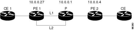
Ethernet over MPLS with MPLS Traffic Engineering Fast Reroute: Example
The following configuration example and Figure 2 show the configuration of Ethernet over MPLS with fast reroute on AToM PE routers.
Routers PE1 and PE2 have the following characteristics:
•
•
•
Figure 2 Fast Reroute Configuration
PE1 Configurationmpls label protocol ldpmpls traffic-eng tunnelsmpls ldp router-id Loopback1 force!pseudowire-class T41encapsulation mplspreferred-path interface Tunnel41 disable-fallback!pseudowire-class IP1encapsulation mplspreferred-path peer 10.4.0.1 disable-fallback!interface Loopback1ip address 10.0.0.27 255.255.255.255!interface Tunnel1ip unnumbered Loopback1tunnel destination 10.0.0.1tunnel mode mpls traffic-engtunnel mpls traffic-eng priority 1 1tunnel mpls traffic-eng bandwidth 10000tunnel mpls traffic-eng path-option 1 explicit name FRR!interface Tunnel41ip unnumbered Loopback1tunnel destination 10.0.0.4tunnel mode mpls traffic-engtunnel mpls traffic-eng priority 1 1tunnel mpls traffic-eng bandwidth 1000tunnel mpls traffic-eng path-option 1 explicit name name-1tunnel mpls traffic-eng fast-reroute!interface POS0/0description pe1name POS8/0/0ip address 10.1.0.2 255.255.255.252mpls traffic-eng tunnelsmpls traffic-eng backup-path Tunnel1crc 16clock source internalpos ais-shutpos report lrdiip rsvp bandwidth 155000 155000!interface POS0/3description pe1name POS10/1/0ip address 10.1.0.14 255.255.255.252mpls traffic-eng tunnelscrc 16clock source internalip rsvp bandwidth 155000 155000!interface gigabitethernet3/0.1encapsulation dot1Q 203xconnect 10.0.0.4 2 pw-class IP1!interface gigabitethernet3/0.2encapsulation dot1Q 204xconnect 10.0.0.4 4 pw-class T41!router ospf 1network 10.0.0.0 0.255.255.255 area 0mpls traffic-eng router-id Loopback1mpls traffic-eng area 0!ip classlessip route 10.4.0.1 255.255.255.255 Tunnel41!ip explicit-path name xxxx-1 enablenext-address 10.4.1.2next-address 10.1.0.10P Configuration
ip cefmpls traffic-eng tunnels!interface Loopback1ip address 10.0.0.1 255.255.255.255!interface FastEthernet1/0/0ip address 10.4.1.2 255.255.255.0mpls traffic-eng tunnelsip rsvp bandwidth 10000 10000!interface POS8/0/0description xxxx POS0/0ip address 10.1.0.1 255.255.255.252mpls traffic-eng tunnelspos ais-shutpos report lrdiip rsvp bandwidth 155000 155000!interface POS10/1/0description xxxx POS0/3ip address 10.1.0.13 255.255.255.252mpls traffic-eng tunnelsip rsvp bandwidth 155000 155000!router ospf 1network 10.0.0.0 0.255.255.255 area 0mpls traffic-eng router-id Loopback1mpls traffic-eng area 0PE2 Configuration
ip cefmpls label protocol ldpmpls traffic-eng tunnelsmpls ldp router-id Loopback1 force!interface Loopback1ip address 10.0.0.4 255.255.255.255!interface loopback 2ip address 10.4.0.1 255.255.255.255!interface Tunnel27ip unnumbered Loopback1tunnel destination 10.0.0.27tunnel mode mpls traffic-engtunnel mpls traffic-eng autoroute announcetunnel mpls traffic-eng priority 1 1tunnel mpls traffic-eng bandwidth 1000tunnel mpls traffic-eng path-option 1 explicit name xxxx-1!interface FastEthernet0/0.2encapsulation dot1Q 203xconnect 10.0.0.27 2 encapsulation mpls!interface FastEthernet0/0.3encapsulation dot1Q 204xconnect 10.0.0.27 4 encapsulation mpls!interface FastEthernet1/1ip address 10.4.1.1 255.255.255.0mpls traffic-eng tunnelsip rsvp bandwidth 10000 10000!router ospf 1network 10.0.0.0 0.255.255.255 area 0mpls traffic-eng router-id Loopback1mpls traffic-eng area 0!ip explicit-path name xxxx-1 enablenext-address 10.4.1.2next-address 10.1.0.10Configuring MTU Values in xconnect Configuration Mode for AToM: Example
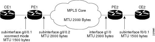
Figure 3 shows a configuration that enables matching MTU values between VC endpoints.
As shown in Figure 3, PE1 is configured in xconnect mode with an MTU value of 1500 bytes in order to establish an end-to-end VC with PE2, that also has an MTU value of 1500 bytes. If PE1 was not set with an MTU value of 1500 bytes, in xconnect mode, the subinterface would inherit the MTU value of 2000 bytes set on the interface. This would cause a mismatch in MTU values between the VC endpoints and the VC would not come up.
Figure 3 Configuring MTU Values in xconnect Configuration Mode
The following examples show the router configurations in Figure 3:
CE1 configuration
interface g0/0mtu 1500no ip address!interface g0/0.1encapsulation dot1Q 100ip address 10.181.182.1 255.255.255.0PE1 configuration
interface g0/0mtu 2000no ip address!interface g0/0.1encapsulation dot1Q 100xconnect 10.1.1.152 100 encapsulation mplsmtu 1500!interface g0/0.2encapsulation dot1Q 200ip address 10.151.100.1 255.255.255.0mpls ipPE2 configuration
interface g1/0mtu 2000no ip address!interface g1/0.2encapsulation dot1Q 200ip address 10.100.152.2 255.255.255.0mpls ip!interface f0/0no ip address!interface f0/0.1description default MTU of 1500 for FastEthernetencapsulation dot1Q 100xconnect 10.1.1.151 100 encapsulation mplsCE2 configuration
interface f0/0no ip addressinterface f0/0.1encapsulation dot1Q 100ip address 10.181.182.2 255.255.255.0The show mpls l2transport binding command, issued from router PE1, shows a matching MTU value of 1500 bytes on both the local and remote routers:
Router# show mpls l2transport bindingDestination Address: 10.1.1.152, VC ID: 100Local Label: 100Cbit: 1, VC Type: Ethernet, GroupID: 0MTU: 1500, Interface Desc: n/aVCCV: CC Type: CW [1], RA [2]CV Type: LSPV [2]Remote Label: 202Cbit: 1, VC Type: Ethernet, GroupID: 0MTU: 1500, Interface Desc: n/aVCCV: CC Type: RA [2]CV Type: LSPV [2]Router# show mpls l2transport vc detailLocal interface: Gi0/0.1 up, line protocol up, Eth VLAN 100 upDestination address: 10.1.1.152, VC ID: 100, VC status: upOutput interface: Gi0/0.2, imposed label stack {202}Preferred path: not configuredDefault path: activeNext hop: 10.151.152.2Create time: 1d11h, last status change time: 1d11hSignaling protocol: LDP, peer 10.1.1.152:0 upTargeted Hello: 10.1.1.151(LDP Id) -> 10.1.1.152MPLS VC labels: local 100, remote 202Group ID: local 0, remote 0MTU: local 1500, remote 1500Remote interface description:Sequencing: receive disabled, send disabledVC statistics:packet totals: receive 41, send 39byte totals: receive 4460, send 5346packet drops: receive 0, send 0Configuring MTU Values in xconnect Configuration Mode for L2VPN Interworking: Example
The following example shows an L2VPN Interworking example. The PE1 router has a serial interface configured with an MTU value of 1492 bytes. The PE2 router uses xconnect configuration mode to set a matching MTU of 1492 bytes, which allows the two routers to form an interworking VC. If the PE2 router did not set the MTU value in xconnect configuration mode, the interface would be set to 1500 bytes by default and the VC would not come up.
PE1 Configuration
pseudowire-class atom-ipiwencapsulation mplsinterworking ip!interface Loopback0ip address 10.1.1.151 255.255.255.255!interface Serial2/0mtu 1492no ip addressencapsulation pppno fair-queueserial restart-delay 0xconnect 10.1.1.152 123 pw-class atom-ipiw!interface Serial4/0ip address 10.151.100.1 255.255.255.252encapsulation pppmpls ipserial restart-delay 0!router ospf 1log-adjacency-changesnetwork 10.1.1.151 0.0.0.0 area 0network 10.151.100.0 0.0.0.3 area 0!mpls ldp router-id Loopback0PE2 Configuration
pseudowire-class atom-ipiwencapsulation mplsinterworking ip!interface Loopback0ip address 10.1.1.152 255.255.255.255!interface Ethernet0/0no ip addressxconnect 10.1.1.151 123 pw-class atom-ipiwmtu 1492!interface Serial4/0ip address 10.100.152.2 255.255.255.252encapsulation pppmpls ipserial restart-delay 0!router ospf 1log-adjacency-changesnetwork 10.1.1.152 0.0.0.0 area 0network 10.100.152.0 0.0.0.3 area 0!mpls ldp router-id Loopback0The show mpls l2transport binding command shows that the MTU value for the local and remote routers is 1492 bytes.
PE1
Router# show mpls l2transport bindingDestination Address: 10.1.1.152, VC ID: 123Local Label: 105Cbit: 1, VC Type: PPP, GroupID: 0MTU: 1492, Interface Desc: n/aVCCV: CC Type: CW [1], RA [2]CV Type: LSPV [2]Remote Label: 205Cbit: 1, VC Type: Ethernet, GroupID: 0MTU: 1492, Interface Desc: n/aVCCV: CC Type: RA [2]CV Type: LSPV [2]Router# show mpls l2transport vc detailLocal interface: Se2/0 up, line protocol up, PPP upMPLS VC type is PPP, interworking type is IPDestination address: 10.1.1.152, VC ID: 123, VC status: upOutput interface: Se4/0, imposed label stack {1003 205}Preferred path: not configuredDefault path: activeNext hop: point2pointCreate time: 00:25:29, last status change time: 00:24:54Signaling protocol: LDP, peer 10.1.1.152:0 upTargeted Hello: 10.1.1.151(LDP Id) -> 10.1.1.152Status TLV support (local/remote) : enabled/supportedLabel/status state machine : established, LruRruLast local dataplane status rcvd: no faultLast local SSS circuit status rcvd: no faultLast local SSS circuit status sent: no faultLast local LDP TLV status sent: no faultLast remote LDP TLV status rcvd: no faultMPLS VC labels: local 105, remote 205Group ID: local n/a, remote 0MTU: local 1492, remote 1492Remote interface description:Sequencing: receive disabled, send disabledVC statistics:packet totals: receive 30, send 29byte totals: receive 2946, send 3364packet drops: receive 0, send 0PE2
Router# show mpls l2transport bindingDestination Address: 10.1.1.151, VC ID: 123Local Label: 205Cbit: 1, VC Type: Ethernet, GroupID: 0MTU: 1492, Interface Desc: n/aVCCV: CC Type: RA [2]CV Type: LSPV [2]Remote Label: 105Cbit: 1, VC Type: Ethernet, GroupID: 0MTU: 1492, Interface Desc: n/aVCCV: CC Type: CW [1], RA [2]CV Type: LSPV [2]Router# show mpls l2transport vc detailLocal interface: Et0/0 up, line protocol up, Ethernet upMPLS VC type is Ethernet, interworking type is IPDestination address: 10.1.1.151, VC ID: 123, VC status: upOutput interface: Se4/0, imposed label stack {1002 105}Preferred path: not configuredDefault path: activeNext hop: point2pointCreate time: 00:25:19, last status change time: 00:25:19Signaling protocol: LDP, peer 10.1.1.151:0 upTargeted Hello: 10.1.1.152(LDP Id) -> 10.1.1.151Status TLV support (local/remote) : enabled/supportedLabel/status state machine : established, LruRruLast local dataplane status rcvd: no faultLast local SSS circuit status rcvd: no faultLast local SSS circuit status sent: no faultLast local LDP TLV status sent: no faultLast remote LDP TLV status rcvd: no faultMPLS VC labels: local 205, remote 105Group ID: local n/a, remote 0MTU: local 1492, remote 1492Remote interface description:Sequencing: receive disabled, send disabledVC statistics:packet totals: receive 29, send 30byte totals: receive 2900, send 3426packet drops: receive 0, send 0Additional References
The following sections provide references related to the Any Transport over MPLS feature.
Related Documents
Any Transport over MPLS
Overview: Cisco Any Transport over MPLS
Any Transport over MPLS for the Cisco 10000 series router
Cisco 10000 Series Router Broadband Aggregation, Leased-Line, and MPLS Configuration Guide
Layer 2 Tunnel Protocol Version 3 (L2TPv3): Provides the ability to tunnel any Layer 2 payload over an IP core network using Layer 2 virtual private networks (L2VPNs)
L2VPN interworking
Standards
MIBs
RFCs
Technical Assistance
Command Reference
This section documents only commands that are new or modified.
•
cell-packing
To enable ATM over Multiprotocol Label Switching (MPLS) or Layer 2 Tunneling Protocol Version 3 (L2TPv3) to pack multiple ATM cells into each MPLS or L2TPv3 packet, use the cell-packing command in the appropriate configuration mode. To disable cell packing, use the no form of this command.
cell-packing [cells] [mcpt-timer timer]
no cell-packing
Syntax Description
Command Default
Cell packing is disabled.
Command Modes
Interface configuration
L2transport VC configuration—for ATM VC
L2transport VP configuration—for ATM VP
VC class configurationCommand History
Usage Guidelines
The cell-packing command is available only if you configure the ATM VC or virtual path (VP) with ATM adaptation layer 0 (AAL0) encapsulation. If you specify ATM adaptation layer 5 (AAL5) encapsulation, the command is not valid.
Only cells from the same VC or VP can be packed into one MPLS or L2TPv3 packet. Cells from different connections cannot be concatenated into the same packet.
When you change, enable, or disable the cell-packing attributes, the ATM VC or VP and the MPLS or L2TPv3 emulated VC are reestablished.
If a provider edge (PE) router does not support cell packing, the PE routers sends only one cell per MPLS or L2TPv3 packet.
The number of packed cells need not match between the PE routers. The two PE routers agree on the lower of the two values. For example, if PE1 is allowed to pack 10 cells per MPLS or L2TPv3 packet and PE2 is allowed to pack 20 cells per MPLS or L2TPv3 packet, the two PE routers would agree to send no more than 10 cells per packet.
If the number of cells packed by the peer PE router exceeds the limit, the packet is dropped.
If you issue the cell-packing command without first specifying the atm mcpt-timers command, you get the following error:
Please set mcpt values firstExamples
The following example shows cell packing enabled on an interface set up for VP mode. The cell-packing command specifies that ten ATM cells be packed into each MPLS packet. The command also specifies that the second maximum cell-packing timeout (MCPT) timer be used.
Router> enableRouter# configure terminalRouter(config)# interface atm1/0Router(config-if)# atm mcpt-timers 1000 800 500Router(config-if)# atm pvp 100 l2transportRouter(config-if-atm-l2trans-pvp)# xconnect 10.0.0.1 234 encapsulation mplsRouter(config-if-atm-l2trans-pvp)# cell-packing 10 mcpt-timer 2The following example configures ATM cell relay over MPLS with cell packing in VC class configuration mode. The VC class is then applied to an interface.
Router> enableRouter# configure terminalRouter(config)# vc-class atm cellpackingRouter(config-vc-class)# encapsulation aal0Router(config-vc-class)# cell-packing 10 mcpt-timer 1Router(config-vc-class)# exitRouter(config)# interface atm1/0Router(config-if)# atm mcpt-timers 100 200 250Router(config-if)# class-int cellpackingRouter(config-if)# pvc 1/200 l2transportRouter(config-if-atm-l2trans-pvc)# xconnect 10.13.13.13 100 encapsulation mplsThe following example configures ATM AAL5 over L2TPv3 in VC class configuration mode. The VC class is then applied to an interface.
Router(config)# vc-class atm aal5classRouter(config-vc-class)# encapsulation aal5!Router(config)# interface atm1/0Router(config-if)# class-int aal5classRouter(config-if)# pvc 1/200 l2transportRouter(config-if-atm-l2trans-pvc)# xconnect 10.13.13.13 100 encapsulation l2tpv3Related Commands
encapsulation (Any Transport over MPLS)
To configure the ATM adaptation layer (AAL) encapsulation for an Any Transport over MPLS (AToM), use the encapsulation command in the appropriate configuration mode. To remove the ATM encapsulation, use the no form of this command.
encapsulation layer-type
no encapsulation layer-type
Syntax Description
layer-type
The adaptation layer type, which is one of the following:
•
•
Command Default
The default encapsulation is AAL5.
Command Modes
L2transport VC configuration—for ATM PVCs
VC class configuration—for VC classCommand History
Usage Guidelines
In L2transport VC configuration mode, the pvc command and the encapsulation command work together. Use the commands for AToM differently than for all other applications. Table 8 shows the differences in how the commands are used.
The following list highlights the differences:
•
•
•
When you use the aal5 keyword, incoming cells (except Operation, Administration, and Maintenance [OAM] cells) on that PVC are treated as AAL5 encapsulated packets. The router reassembles the packet from the incoming cells. The router does not check the contents of the packet, so it does not need to know the encapsulation type (such as aal5snap and aal5mux). After imposing the Multiprotocol Label Switching (MPLS) label stack, the router sends the reassembled packet over the MPLS core network.
When you use the aal0 keyword, the router strips the header error control (HEC) byte from the cell header and adds the MPLS label stack. The router sends the cell over the MPLS core network.
Examples
The following example shows how to configure a PVC to transport ATM cell relay packets for AToM:
Router> enableRouter# configure terminalRouter(config)# interface atm1/0Router(config-if)# pvc 1/100 l2transportRouter(config-if-atm-l2trans-pvc)# encapsulation aal0Router(config-if-atm-l2trans-pvc)# xconnect 10.13.13.13 100 encapsulation mplsThe following example shows how to configure ATM AAL5 over MPLS in VC class configuration mode. The VC class is applied to a PVC.
Router> enableRouter# configure terminalRouter(config)# vc-class atm aal5classRouter(config-vc-class)# encapsulation aal5Router(config)# interface atm1/0Router(config-if)# pvc 1/200 l2transportRouter(config-if-atm-l2trans-pvc)# class-vc aal5classRouter(config-if-atm-l2trans-pvc)# xconnect 10.13.13.13 100 encapsulation mplsRelated Commands
oam-ac emulation-enable
To enable Operation, Administration, and Maintenance (OAM) cell emulation on ATM adaptation layer 5 (AAL5) over Multiprotocol Label Switching (MPLS) or Layer 2 Tunnel Protocol Version 3 (L2TPv3), use the oam-ac emulation-enable command in the appropriate configuration mode on both provider edge (PE) routers. To disable OAM cell emulation, use the no form of this command on both routers.
oam-ac emulation-enable [seconds]
no oam-ac emulation-enable [seconds]
Syntax Description
Command Default
OAM cell emulation is disabled.
Command Modes
L2transport VC configuration—for an ATM PVC
VC class configuration mode—for a VC classCommand History
Usage Guidelines
This command is used with AAL5 over MPLS or L2TPv3 and is not supported with ATM cell relay over MPLS or L2TPv3.
Examples
The following example shows how to enable OAM cell emulation on an ATM permanent virtual circuit (PVC):
Router# interface ATM 1/0/0Router(config-if)# pvc 1/200 l2transport
Router(config-if-atm-l2trans-pvc)# oam-ac emulation-enableThe following example shows how to set the rate at which an AIS cell is sent every 30 seconds:
Router# interface ATM 1/0/0Router(config-if)# pvc 1/200 l2transport
Router(config-if-atm-l2trans-pvc)# oam-ac emulation-enable 30The following example configures OAM cell emulation for ATM AAL5 over MPLS in VC class configuration mode. The VC class is then applied to an interface.
Router> enableRouter# configure terminalRouter(config)# vc-class atm oamclassRouter(config-vc-class)# encapsulation aal5Router(config-vc-class)# oam-ac emulation-enable 30
Router(config-vc-class)# oam-pvc manage
Router(config)# interface atm1/0Router(config-if)# class-int oamclassRouter(config-if)# pvc 1/200 l2transportRouter(config-if-atm-l2trans-pvc)# xconnect 10.13.13.13 100 encapsulation mplsRelated Commands
Feature Information for Any Transport over MPLS
Table 9 lists the release history for this feature.
Not all commands may be available in your Cisco IOS software release. For release information about a specific command, see the command reference documentation.
Cisco IOS software images are specific to a Cisco IOS software release, a feature set, and a platform. Use Cisco Feature Navigator to find information about platform support and Cisco IOS software image support. Access Cisco Feature Navigator at http://www.cisco.com/go/fn. You must have an account on Cisco.com. If you do not have an account or have forgotten your username or password, click Cancel at the login dialog box and follow the instructions that appear.
Note
Table 9 Feature Information for Any Transport over MPLS
Any Transport over MPLS
12.0(10)ST
Any Transport over MPLS: ATM AAL5 over MPLS was introduced on the Cisco 12000 series routers.
12.1(8a)E
In 12.1(8a)E, Ethernet over MPLS was introduced on the Cisco 7600 series Internet router.
12.0(21)ST
Any Transport over MPLS: Ethernet over MPLS was introduced on the Cisco 12000 series routers. ATM AAL5 over MPLS was updated.
12.0(22)S
In 12.0(22)S, Ethernet over MPLS was integrated into this release. Support for the Cisco 10720 Internet router was added. ATM AAL5 over MPLS was integrated into this release for the Cisco 12000 series routers.
12.0(23)S
In 12.0(23)S, the following new features were introduced:
•
•
•
•
These features were supported on the Cisco 7200 and 7500 series routers.
The Cisco 12000, 7200, and 7500 series routers added support for the following features:
•
•
12.2(14)S
The AToM features were integrated into Cisco IOS Release 12.2(14)S.
12.2(15)T
The AToM features were integrated into Cisco IOS Release 12.2(15)T.
12.0(25)S
In 12.0(25)S, the following new features were introduced:
•
•
•
•
•
•
•
•
•
•
12.0(26)S
In 12.0(26)S, the following new features were introduced:
•
•
•
12.0(27)S
In 12.0(27)S, the following new features were introduced:
•
Cisco 12000 series router.•
12.2(25)S
This feature was integrated into Cisco IOS Release 12.2(25)S for the Cisco 7200 and 7500 series routers.
12.0(29)S
In 12.0(29)S, the "Any Transport over MPLS Sequencing Support" feature was added for the Cisco 7200 and 7500 series routers. See the Any Transport over MPLS (AToM) Sequencing Support document for more information.
12.0(30)S
In 12.0(30)S, the following new features were introduced:
•
•
12.0(31)S
In 12.0(31)S, the Cisco 12000 series router introduced the following enhancements:
•
•
12.0(32)S
In 12.0(32)S, the Cisco 12000 series router added engine 5 line card support for the following transport types:
•
•
•
•
12.2(28)SB
This feature was integrated into Cisco IOS Release 12.2(28)SB on the Cisco 10000 series routers. Platform-specific configuration information is contained in the "Configuring Any Transport over MPLS" section of the Cisco 10000 Series Router Broadband Aggregation, Leased-Line, and MPLS Configuration Guide.
12.4(11)T
Any Transport over MPLS was integrated into Cisco IOS Release 12.4(11)T and supports the following features:
•
•
•
•
•
•
12.2(33)SRB
This feature was integrated into Cisco IOS Release 12.2(33)SRB to support the following features on the Cisco 7600 router:
•
•
•
•
Platform-specific configuration information is contained in the following documents:
•
•
•
•
•
•
12.2(33)SXH
This feature was integrated into Cisco IOS Release 12.2(33)SXH and supports the following features:
•
•
•
•
•
•
•
•
•
12.2(33)SRC
This feature was integrated into Cisco IOS Release 12.2(33)SRC and supports the following features:
•
•
•
CCVP, the Cisco logo, and the Cisco Square Bridge logo are trademarks of Cisco Systems, Inc.; Changing the Way We Work, Live, Play, and Learn is a service mark of Cisco Systems, Inc.; and Access Registrar, Aironet, BPX, Catalyst, CCDA, CCDP, CCIE, CCIP, CCNA, CCNP, CCSP, Cisco, the Cisco Certified Internetwork Expert logo, Cisco IOS, Cisco Press, Cisco Systems, Cisco Systems Capital, the Cisco Systems logo, Cisco Unity, Enterprise/Solver, EtherChannel, EtherFast, EtherSwitch, Fast Step, Follow Me Browsing, FormShare, GigaDrive, HomeLink, Internet Quotient, IOS, iPhone, IP/TV, iQ Expertise, the iQ logo, iQ Net Readiness Scorecard, iQuick Study, LightStream, Linksys, MeetingPlace, MGX, Networking Academy, Network Registrar, Packet, PIX, ProConnect, ScriptShare, SMARTnet, StackWise, The Fastest Way to Increase Your Internet Quotient, and TransPath are registered trademarks of Cisco Systems, Inc. and/or its affiliates in the United States and certain other countries.
All other trademarks mentioned in this document or Website are the property of their respective owners. The use of the word partner does not imply a partnership relationship between Cisco and any other company. (0705R)
Any Internet Protocol (IP) addresses used in this document are not intended to be actual addresses. Any examples, command display output, and figures included in the document are shown for illustrative purposes only. Any use of actual IP addresses in illustrative content is unintentional and coincidental.
© 2001-2007 Cisco Systems, Inc. All rights reserved.