-
Cisco 7304 Router Modular Services Card and Shared Port Adapter Hardware Installation Guide
-
Title Page
-
Preface
-
MSCs and SPA Product Overview
-
Overview: Cisco 7304 Router Carrier Cards
-
Overview: Cisco 7304 Router Shared Port Adapters
-
Preparing to Install a Modular Services Card or a Shared Port Adapter
-
Installing and Removing a Carrier Card
-
Installing and Removing a Shared Port Adapter
-
Troubleshooting the Installation
-
 Feedback
Table Of Contents
Overview: Cisco 7304 Router Shared Port Adapters
Checking Hardware and Software Compatibility
Cables, Connectors, and Pinouts
Cables, Connectors, and Pinouts
SFP Module Cabling and Connection Equipment
2-Port and 4-Port OC-3c/STM-1 POS SPA LEDs
2-Port and 4-Port OC-3c/STM-1 POS SPA Interface Specifications
2-Port and 4-Port OC-3c/STM-1 POS SPA Optical Transceiver Modules and Cables
1-Port OC-12c/STM-4 POS SPA LEDs
1-Port OC-12c/STM-4 POS SPA Interface Specifications
1-Port OC-12c/STM-4 POS SPA SFP Optical Transceiver Modules and Cables
2-Port and 4-Port T3/E3 Serial SPA LEDs
2-Port and 4-Port T3/E3 Serial SPA Interface Specifications
2-Port and 4-Port T3/E3 Serial SPA Cables and Connectors
Overview: Cisco 7304 Router Shared Port Adapters
This chapter describes the shared port adapters (SPAs) that are supported on the Cisco 7304 router and contains the following sections:
•
OC-12 POS SPA Overview, page 3-12
•
SPA Summary
Summary descriptions of the SPAs that are supported on the Cisco 7304 router are shown in Table 3-1.
Table 3-1 SPA Summary for Cisco 7304 Routers
Checking Hardware and Software Compatibility
To check the minimum software requirements of Cisco IOS software with the hardware installed on your router, Cisco maintains the Software Advisor tool on Cisco.com. This tool does not verify whether MSCs or SPAs within a system are compatible, but it does provide the minimum Cisco IOS requirements for individual hardware modules or components.
Note
To access Software Advisor, click Login at Cisco.com, type "Software Advisor" in the SEARCH box, and click GO. Click the link for the Software Advisor tool.
Choose a product family or enter a specific product number to search for the minimum supported software release needed for your hardware.
Bandwidth Oversubscription
For information on bandwidth oversubscription on the Cisco 7304 router, including information on how SPAs and carrier cards impact the overall bandwidth of the router, see Bandwidth Information for Cisco 7304 Routers.
FastEthernet SPA Overview
The following sections describe the SPA-4FE-7304:
•
•
LEDs
The SPA-4FE-7304 has the LEDs shown in Figure 3-1.
Figure 3-1 SPA-4FE-7304 Faceplate
The SPA-4FE-7304 LEDs are described in Table 3-2.
Table 3-2
STATUS
Green
On
The SPA is online.
Yellow
On
The SPA is receiving power and bootstrapping.
Off
Off
The SPA is offline and deactivated.
Port Number (0, 1, 2, or 3)1
Green
On
The port is enabled and the link is up.
Yellow
On
The port is enabled and the link is down.
Off
Off
The port is disabled.
1 In this case, port number refers to the numbered LEDs on the SPA-4FE-7304 (0, 1, 2, or 3). Each LED number on the FastEthernet SPA references a port on the SPA.
SPA-4FE-7304 LEDs
Cables, Connectors, and Pinouts
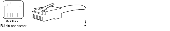
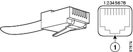
The interface connectors on the SPA-4FE-7304 are four individual RJ-45 receptacles. You can use all four interface connectors simultaneously. Each connection supports IEEE 802.3 and Ethernet 10BASE-T interfaces compliant with appropriate standards. The RJ-45 connections require external transceivers. Cisco Systems does not supply Category 5 unshielded twisted-pair (UTP) RJ-45 cables; these cables are available commercially.
Figure 3-2 shows the RJ-45 connector. Table 3-3 lists the pinouts and signals for the RJ-45 connector.
Figure 3-2 RJ-45 Connections, Plug, and Receptacle
Table 3-3 RJ-45 Connector Pinout
1
Transmit data + (TxD+)
2
TxD-
3
Receive data + (RxD+)
6
RxD-
Note
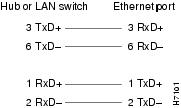
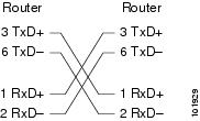
Depending on your RJ-45 interface cabling requirements, use the pinouts in Figure 3-3 and Figure 3-4.
Figure 3-3 Straight-Through Cable Pinout, RJ-45 Connection to a Hub or Repeater
Figure 3-4 Crossover Cable Pinout, RJ-45 Connections Between Routers
GigabitEthernet SPA Overview
The following sections describe the SPA-2GE-7304:
•
•
•
LEDs
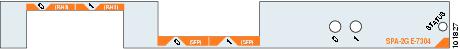
The SPA-2GE-7304 has three LEDs, as shown in Figure 3-5.
Figure 3-5 SPA-2GE-7304 Faceplate
The SPA-2GE-7304 LEDs are described in Figure 3-5.
Table 3-4 SPA-2GE-7304 LEDs
STATUS
Green
On
The SPA is online.
Yellow
On
The SPA is receiving power and bootstrapping.
Off
Off
The SPA is offline and deactivated.
Port Number (0 or 1)1
Green
On
The port is enabled and the link is up.
Yellow
On
The port is enabled and the link is down.
Off
Off
The port is disabled.
1 In this case, port number refers to the numbered LEDs on the SPA-2GE-7304 (0 or 1). Each LED number on the GigabitEthernet SPA references a port on the SPA.
Cables, Connectors, and Pinouts
The interface connectors on the SPA-2GE-7304 are two individual RJ-45 receptacles and two fiber optic receivers that support SFPs. It is import to note that the SPA-2GE-7304 can only send and receive traffic from two ports, port 0 and port 1. Each port can send and receive traffic using either the RJ-45 port or the optical fiber connection.
The following sections describe the cable, connection, and pinout requirements for the SPA-2GE-7304:
RJ-45 Connectors
The SPA-2GE-7304 router has two RJ-45 ports for 10/100/1000 Ethernet/FastEthernet/GigabitEthernet connections. The RJ-45 ports support IEEE 802.3ab (Gigabit Ethernet) and IEEE 802.3u (Fast Ethernet) interfaces compliant with 10BASE-T, 100BASE-TX, and 1000BASE-T specifications.
The RJ-45 ports support standard straight-through and crossover Category 5 UTP cables with RJ-45 connectors. Cisco Systems does not supply Category 5 UTP cables; these cables are available commercially.
Warning
Figure 3-6 shows an RJ-45 connector. Table 3-5 lists the pinouts and signals for the RJ-45 port.
Figure 3-6 RJ-45 Port and Connector
Table 3-5 RJ-45 Receptacle Pinouts
1
Tx A+1
2
Tx A-
3
Rx B+2
4
Tx C+
5
Tx C-
6
Rx B-
7
Rx D+
8
Rx D-
1 TX DATA = Transmit Data
2 RX DATA = Receive Data
SFP Connections
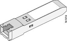
The small form-factor pluggable (SFP) module is an input/output (I/O) device that plugs into the Gigabit Ethernet optical slot on the SPA-2GE-7304, linking the port with a 1000BASE-X fiber-optic network. An SFP module is shown in Figure 3-7.
Note
SFP modules exist for technologies other than Gigabit Ethernet and for products other than the SPA-2GE-7304. However, the information in this document pertains only to SFP modules that plug into the SPA-2GE-7304 fiber-optic ports.Figure 3-7 SFP Module
The SFP module has a receiver port (RX) and a transmitter port (TX) that compose one optical interface. Table 3-6, Table 3-7, and Table 3-8 provide SFP module information and specifications.
Table 3-7 SFP Module Transmit Power, Receive Power, and Power Budget
SFP-FCGE-S
-9.5 dBm1
-4 dBm1
-17 dBm
0 dBm
SFP-FCGE-L
-9.5 dBm2
-3 dBm3
-19 dBm
-3 dBm
SFP-GE-Z
0 dBm
5 dBm
-23 dBm
-3 dBm
1 For fiber types 50/125 mm, NA = 0.20 fiber and 62.5/125 mm, NA = 0.275 fiber.
2 For fiber types 9/125 mm SMF.
3 For fiber types 9/125 mm SMF, 62.5/125 mm MMF, and 50/125 mm MMF.
SFP-FCGE-S Modules
The 1000BASE-SX (short wavelength) module operates on standard multimode fiber-optic link spans of up to 1804 feet (550 m). (See Table 3-9.)
SFP-FCGE-L Modules
The 1000BASE-LX/LH (long wavelength/long haul) module interfaces fully comply with the IEEE 802.3z 1000BASE-LX standard. However, their higher optical quality allows them to reach 6.2 miles (10 km) over single-mode fiber (SMF) versus the 3.1 miles (5 km) specified in the standard. (See Table 3-9.)
SFP-GE-Z Modules
The 1000BASE-ZX (extended wavelength) module operates on ordinary single-mode fiber-optic link spans of up to 43.5 miles (70 km). Link spans of up to 62.1 miles (100 km) are possible using premium single-mode fiber or dispersion-shifted single-mode fiber (premium single-mode fiber has a lower attenuation per unit length than ordinary single-mode fiber; dispersion-shifted single-mode fiber has both lower attenuation and less dispersion).
The 1000BASE-ZX module must be coupled to single-mode fiber-optic cable, which is the type of cable typically used in long-haul telecommunications applications. The 1000BASE-ZX module will not operate correctly when coupled to multimode fiber, and it is not intended to be used in environments where multimode fiber is frequently used (for example, building backbones, or horizontal cabling).
The 1000BASE-ZX module is intended to be used as a Physical Medium Dependent (PMD) component for Gigabit Ethernet interfaces found on various switch and router products. It operates at a signaling rate of 1250 Mbaud, transmitting and receiving 8B/10B encoded data.
When shorter lengths of single-mode fiber are used, it may be necessary to insert an in-line optical attenuator in the link to avoid overloading the receiver.
•
•
SFP Module Cabling and Connection Equipment
Table 3-9 provides cabling specifications for the SFP modules that can be installed on the SPA-2GE-7304. Note that all SFP ports have LC-type connectors.
The minimum cable distance for the SFP-FCGE-S is 6.5 feet (2 m), and the minimum link distance for the SFP-GE-Z is 6.2 miles (10 km) with an 8-dB attenuator installed at each end of the link. Without attenuators, the minimum link distance for the SFP-GE-Z is 24.9 miles (40 km).
Table 3-9 SFP Module Port Cabling Specifications
Cable DistanceSFP-FCGE-S
850
MMF1
62.5
160
722 ft (220 m)
62.5
200
902 ft (275 m)
50.0
400
1640 ft (500 m)
50.0
500
1804 ft (550 m)
SFP-FCGE-L
1300
MMF2 and SMF
62.5
500
1804 ft (550 m)
50.0
400
1804 ft (550 m)
50.0
500
1804 ft (550 m)
9/10
—
6.2 miles (10 km)
SFP-GE-Z
1550
SMF
9/10
—
49.7 miles (80 km)
SMF3
8
—
62.1 miles (100 km)
1 Multimode fiber (MMF) only.
2 A mode-conditioning patch cord is required.
When using the SFP-FCGE-L with 62.5-micron diameter MMF, you must install a mode-conditioning patch cord between the SFP module and the MMF cable on both the transmit and the receive ends of the link when link distances are greater than 984 ft (300 m).
We do not recommend using the SFP-FCGE-L and MMF with no patch cord for very short link distance (tens of meters). The result could be an elevated bit error rate (BER).3 Dispersion-shifted single-mode fiber-optic cable.
Note
CWDM SFPs
CWDM SFPs were first supported on the SPA-2GE-7304 in Cisco IOS Release 12.2(28)SB. CWDM SFPs for the SPA-2GE-7304 come in eight wavelengths that range from 1470 nm to 1610 nm. Color markings on the devices identify the wavelength to which the Gigabit Ethernet channel is mapped. Table 3-10 lists the CWDM SFPs with their wavelengths and color codes that are supported on the SPA-2GE-7304.
Table 3-10 CWDM SFP Wavelengths and Color Coding
For more detailed information on these CWDM SFP modules, see the Cisco CWDM GBIC and SFP Solution Data Sheet.
OC-3 POS SPA Overview
The 2-Port and 4-Port OC-3c/STM-1 POS SPA is a single-height SPA that installs into one MSC subslot. The OC-3c/STM-1 POS SPA with small form-factor pluggable (SFP) optical transceiver modules provides SONET and SDH network connectivity with a per-port bandwidth of 155.52 Mbps.
For more information about SPA bandwidth, see the "Bandwidth Oversubscription" topic in this chapter. For more information about SPAs and their compatibility with MSCs and modular optics, see the "MSC and SPA Product Overview" chapter in this guide.
The following sections describe the 2-Port and 4-Port OC-3c/STM-1 POS SPA :
•
•
•
2-Port and 4-Port OC-3c/STM-1 POS SPA LEDs
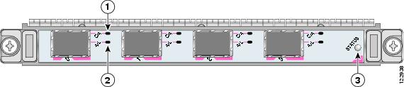
The 2-Port and 4-Port OC-3c/STM-1 POS SPA has three LEDs, as shown in Figure 3-8. There are two LEDs for each port on the SPA, and one STATUS LED.
Figure 3-8 4-Port OC-3c/STM-1 POS SPA Faceplate
The 2-Port and 4-Port OC-3c/STM-1 POS SPA LEDs are described in Table 3-11.
2-Port and 4-Port OC-3c/STM-1 POS SPA Interface Specifications
The framer processes incoming and outgoing SONET or SDH frames. The framer operates at OC-3c/STM-1 line rates (155.52 Mbps).
Packet data is transported with a user-configured encapsulation (such as Point-to-Point Protocol [PPP]) and is mapped into the STS-3c/STM-1 frame.
The 2-Port and 4-Port OC-3c/STM-1 POS SPA interface is compliant with the following RFCs:
•
•
The 2-Port and 4-Port OC-3c/STM-1 POS SPA also provides support for SNMP agent v1 (RFC 1155-1157) and RFC 1213:
•
•
•
•
2-Port and 4-Port OC-3c/STM-1 POS SPA Optical Transceiver Modules and Cables
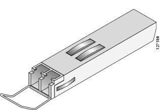
The 2-Port and 4-Port OC-3c/STM-1 POS SPA uses a small form-factor pluggable (SFP) optical transceiver module installed in each port for SONET and SDH single-mode and multimode optical fiber connection (See Figure 3-9).
Cisco Systems qualifies the optics that are approved for use with its SPAs. The 2-Port and 4-Port OC-3c/STM-1 POS SPA supports the following types of optical transceiver modules:
•
•
•
•
•
Figure 3-9 SFP Optics Module
The SFP optical transceiver modules used with the 2-Port and 4-Port OC-3c/STM-1 POS SPA provide the following optical fiber options:
•
Use a multimode optical fiber that has a core/cladding diameter of 62.5/125 microns.
•
Use a single-mode optical fiber that has a modal-field diameter of 8.7 ± 0.5 microns. (Nominal diameter is approximately 10/125 microns.)
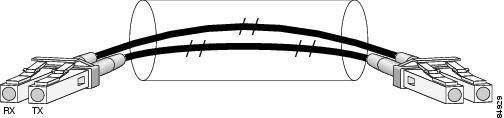
For single-mode and multimode optical fiber connections, you can use either a duplex LC-type cable (see Figure 3-10) or two simplex LC-type cables, one for transmit (TX) and one for receive (RX).
Use single-mode (for intermediate- or long-reach configurations) or multimode optical fiber cable to connect your router to a network or to connect two OC-3c/STM-1-equipped routers back-to-back.
Long-range SFP optical transceiver modules (for long-reach configurations) cannot be connected back-to-back without using an attenuator between the two of them.
Figure 3-10 LC-Type Cable
OC-12 POS SPA Overview
The 1-Port OC-12c/STM-4 POS SPA is single-height SPA that installs into one MSC subslot. The 1-Port OC-12c/STM-4 POS SPA with a small form-factor pluggable (SFP) optical transceiver module provides SONET and SDH network connectivity with a bandwidth of 622.08 Mbps.
For more information about SPA bandwidth, see the "Bandwidth Oversubscription" topic in this chapter. For more information about SPAs and their compatibility with MSCs and modular optics, see the "MSC and SPA Product Overview" chapter in this guide.
The following sections describe the 1-Port OC-12c/STM-4 POS SPA:
•
•
•
1-Port OC-12c/STM-4 POS SPA LEDs
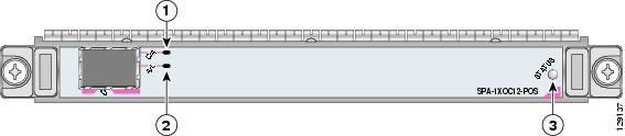
The 1-Port OC-12c/STM-4 POS SPA has three types of LEDs. There are two LEDs for each port on the SPA, and one STATUS LED. Figure 3-11 shows an example of these LEDs on a 1-Port OC-12c/STM-4 POS SPA.
Figure 3-11 1-Port OC-12c/STM-4 POS SPA Faceplate
The 1-Port OC-12c/STM-4 POS SPA LEDs are described in Table 3-12.
1-Port OC-12c/STM-4 POS SPA Interface Specifications
The framer processes incoming and outgoing SONET or SDH frames. The framer operates at OC-12c/STM-4 line rates (622.08 Mbps).
Packet data is transported with a user-configured encapsulation (such as Point-to-Point Protocol [PPP]) and is mapped into the STS-12c/STM-4 frame.
The 1-Port OC-12c/STM-4 POS SPA interface is compliant with the following RFCs:
•
•
The 1-Port OC-12c/STM-4 POS SPA also provides support for SNMP v1 agent (RFC 1155-1157) and RFC 1213:
•
•
•
•
1-Port OC-12c/STM-4 POS SPA SFP Optical Transceiver Modules and Cables
The POS SPA uses a small form-factor pluggable (SFP) optical transceiver module installed in each port for SONET and SDH single-mode and multimode optical fiber connection (see Figure 3-12).
Cisco Systems qualifies the optics that are approved for use with its SPAs. The 1-Port OC-12c/STM-4 POS SPA supports the following types of optical transceiver modules:
•
•
•
•
•
Figure 3-12 SFP Optics Module
The SFP optical transceiver modules used with the POS SPAs provide the following optical fiber options:
•
Use a multimode optical fiber that has a core/cladding diameter of 62.5/125 microns.
•
Use a single-mode optical fiber that has a modal-field diameter of 8.7 ±0.5 microns. (Nominal diameter is approximately 10/125 microns.)
For single-mode and multimode optical fiber connections, you can use either a duplex LC-type cable (see Figure 3-13) or two simplex LC-type cables, one for transmit (TX) and one for receive (RX).
Use single-mode (for intermediate- or long-reach configurations) or multimode optical fiber cable to connect your router to a network or to connect two 1-Port OC-12c/STM-4 POS SPA-equipped routers back to back.
Long-range SFP optical transceiver modules (for long-reach configurations) cannot be connected back-to-back without using an attenuator between the two of them.
Figure 3-13 LC-Type Cable
T3/E3 Serial SPA Overview
The following sections describe the 2-Port and 4-Port T3/E3 Serial SPA:
•
•
•
2-Port and 4-Port T3/E3 Serial SPA LEDs
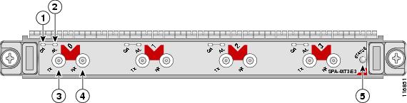
The 2-Port and 4-Port T3/E3 Serial SPA has three types of LEDs. There are two LEDs for each port on the SPA, and one STATUS LED. Figure 3-14 shows an example of these LEDs on a 4-Port T3/E3 Serial SPA.
Figure 3-14 4-Port T3/E3 Serial SPA Faceplate
C/A (Carrier/Alarm) LED
RX (Receive) connector
A/L (Active Loopback) LED
STATUS LED
TX (Transmit) connector
The 2-Port and 4-Port T3/E3 Serial SPA LEDs are described in Table 3-13.
2-Port and 4-Port T3/E3 Serial SPA Interface Specifications
The framer processes incoming and outgoing T3 (cbit, m13/m23, and unframe) and E3 (g751, g832, and unframe) frames. The framer operates at T3/E3 line rates (44.2/34.0 Mbps) depending on which mode it is configured in.
Packet data is transported with a user-configurable encapsulation (such as Point-to-Point Protocol [PPP] or High-Level Data Link Control [HDLC]), and is mapped to T3 and E3 frames. The encapsulations add transport overhead to the packet of data frames before transporting, and are stripped when a packet is transported to the far end.
The T3/E3 SPA interface is compliant with ANSI and Telco standards. The interface also provides support for Management Information Base (MIB) (RFC 2496) and T1.231.
2-Port and 4-Port T3/E3 Serial SPA Cables and Connectors
The interface connectors on the 2-Port and 4-Port T3/E3 Serial SPA are 75-ohm coaxial Siemax types, with one connector and cable for transmit (TX) and one for receive (RX).
The following cables can be used with the 2-Port and 4-Port T3/E3 Serial SPA. The cables have BNC on one end and the Siemax connectors on the other.
•
•
•
Note
Figure 3-14 shows the connectors on the 4-Port T3/E3 Serial SPA, and Table 3-14 describes the signal descriptions for these connectors.