-
Cisco 7304 Router Modular Services Card and Shared Port Adapter Hardware Installation Guide
-
Title Page
-
Preface
-
MSCs and SPA Product Overview
-
Overview: Cisco 7304 Router Carrier Cards
-
Overview: Cisco 7304 Router Shared Port Adapters
-
Preparing to Install a Modular Services Card or a Shared Port Adapter
-
Installing and Removing a Carrier Card
-
Installing and Removing a Shared Port Adapter
-
Troubleshooting the Installation
-
 Feedback
Table Of Contents
Overview: Cisco 7304 Router Carrier Cards
Carrier Card and SPA Compatibility
Checking Hardware and Software Compatibility
Carrier Card Slot Locations on the Cisco 7304 Router
SPA Slot Numbering on the MSC-100
SPA Interface Addresses on MSCs
Overview: Cisco 7304 Router Carrier Cards
This chapter describes the carrier cards that are supported on the Cisco 7304 router and contains the following sections:
•
Carrier Card and SPA Compatibility
Carrier Card and SPA Compatibility
For information on carrier card and SPA compatibility, see the "MSC and SPA Compatibility" section.
Carrier Card Summary
Summary descriptions of the carrier cards that are supported on the Cisco 7304 router are shown in Table 2-1.
Table 2-1
MSC-100
7304-MSC-100
Modular Services Card 100
2
Release 12.2(20)S2
Carrier Card Summary
Checking Hardware and Software Compatibility
To check the minimum software requirements of Cisco IOS software with the hardware installed on your router, Cisco maintains the Software Advisor tool on Cisco.com. This tool does not verify whether carrier cards or SPAs within a system are compatible, but it does provide the minimum Cisco IOS requirements for individual hardware modules or components.
Note
To access Software Advisor, click Login at Cisco.com, type "Software Advisor" in the SEARCH box, and click GO. Click the link for the Software Advisor tool.
Choose a product family or enter a specific product number to search for the minimum supported software release needed for your hardware.
SPA Blank Filler Plates
SPA blanks are available to fill and unused SPA slot.
Note
MSC-100 Overview
The following sections describe the MSC-100:
•
•
•
•
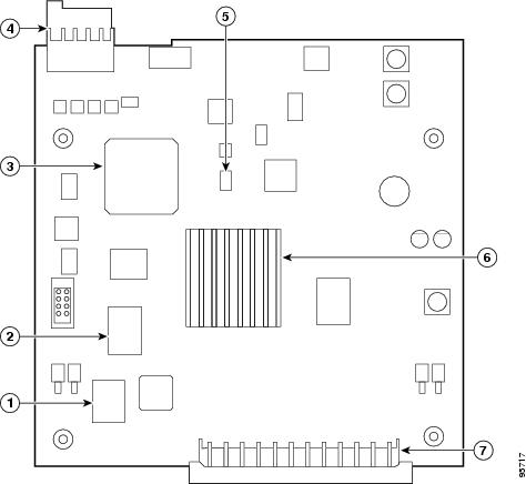
Board Components
The main MSC-100 board components are shown in Figure 2-1.
Figure 2-1 MSC-100 Board—Overhead View
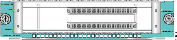
LEDs
The MSC-100 has four LEDs, as shown in Figure 2-2.
Figure 2-2 MSC-100 Faceplate
MSC-100 LEDs are described in Table 2-2.
Physical Specifications
The MSC-100 physical specifications are shown in Table 2-3.
Carrier Card Slot Locations on the Cisco 7304 Router
The MSC-100 can be installed in Cisco 7304 router module slots 2 through 5.
Figure 2-3 Module Slots on the Cisco 7304 Router
SPA Slot Numbering on the MSC-100
The MSC-100 accepts two single-height SPAs. The top subslot in the MSC is subslot 0 and the bottom subslot is subslot 1.
SPA Interface Addresses on MSCs
Interface addresses specify the physical location of each interface on a router or switch. Table 2-4 describes how to identify the interface addresses for SPAs supported on the MSC-100.
Table 2-4 Address Format