-
Cisco CMTS Feature Guide, Release 12.3BC
-
Title Pages
-
Preface
-
Admission Control for the Cisco Cable Modem Termination System
-
Cable Duplicate MAC Address Reject for the Cisco CMTS
-
Cable Interface Bundling and Virtual Interface Bundling for the Cisco CMTS
-
Cable Monitor and Intercept Features on the Cisco CMTS
-
COPS Engine Operation on the Cisco CMTS
-
DHCP, ToD, and TFTP Services for the Cisco Cable Modem Termination System
-
DOCSIS 1.1 for the Cisco CMTS
-
DOCSIS 2.0 A-TDMA Services on the Cisco CMTS
-
EtherChannel on the Cisco Cable Modem Termination System
-
Flap List Troubleshooting for the Cisco CMTS
-
Maximum CPE or Host Parameters for the Cisco Cable Modem Termination System
-
N+1 Redundancy for the Cisco Cable Modem Termination System
-
PacketCable and PacketCable Multimedia for the Cisco CMTS
-
Point-to-Point Protocol over Ethernet Support on the Cisco CMTS
-
Service Flow Admission Control for the Cisco CMTS
-
Service Flow Mapping to MPLS-VPN on the Cisco CMTS
-
Spectrum Management and Advanced Spectrum Management for the Cisco CMTS
-
Telco Return for the Cisco CMTS
-
Time-of-Day Server for the Cisco CMTS
-
Unique Device Identifier Retrieval for the Cisco CMTS
-
Upstream Scheduler Mode for the Cisco CMTS
-
Glossary
-
 Feedback
Table Of Contents
Spectrum Management and Advanced Spectrum Management for the Cisco CMTS
Prerequisites for Spectrum Management and Advanced Spectrum Management
Restrictions for Spectrum Management
Cisco IOS Releases and Cable Interface Line Card Support
Fixed-Frequency Spectrum Groups with Advanced Spectrum Management
Limitations on Upstream Modulation Parameters for PacketCable VoIP Calls
HCCP 1+1 and N+1 Redundancy Support
Intelligent and Advanced Spectrum Management Support
Information About Spectrum Management
Spectrum Management Measurements
Signal and Carrier Noise Ratios
Differences Between the SNR and CNR Values
Upstream Signal Channel Overview
Upstream Segments and Combiner Groups
Spectrum Groups and Frequency Hopping
Guidelines for Spectrum Management
Guided and Scheduled Spectrum Management
Frequency Hopping Capabilities
Dynamic Upstream Modulation (SNR-Based)
Intelligent and Advanced Hardware-Based Spectrum Management
Intelligent Spectrum Management Enhancements
Advanced Spectrum Management Support Using the Cisco uBR10-MC5X20S/U/H BPE
Guided and Scheduled Spectrum Management Benefits
Intelligent and Advanced Spectrum Management Benefits
How to Configure Spectrum Management
Guided and Scheduled Spectrum Management Configuration Tasks
Enabling Upstream Rate Limiting
Enabling Downstream Rate Limiting
Creating and Configuring Spectrum Groups
Assigning a Spectrum Group to One or More Upstream Ports
Configuring Shared Spectrum Groups (Fiber Node Groups) for DOCSIS 3.0
Configuring Dynamic Upstream Modulation (SNR-Based)
Intelligent and Advanced Spectrum Management Configuration Tasks
Configuring and Assigning Spectrum Groups
Configuring Dynamic Upstream Modulation (CNR-Based)
Configuring Proactive Channel Management
Verifying the Spectrum Management Configuration
Monitoring Spectrum Management
Upstream Traffic Shaping and Rate Limiting Examples
Configuring the Low-Peak-Rate Limit Example
Applying the Rate-Limiting Algorithm Without Rate Limiting Example
Forcing the Cable Modem to Exceed the Peak Rate Example
Downstream Traffic Shaping and Rate Limiting Examples
Downstream Rate Limiting Example
Verifying Downstream Rate Limiting Example
Spectrum Group and Combiner Group Examples
Verifying Spectrum Group Creation Example
Time-Scheduled Spectrum Group Example
Verifying Spectrum Group Configuration Example
Determining the Upstream Ports Assigned to a Combiner Group Example
Other Spectrum Management Configuration Examples
Dynamic Upstream Modulation Examples
Advanced Spectrum Management Configuration Examples
Advanced Spectrum Management for the Cisco uBR7200 Series Router Example
Advanced Spectrum Management for the Cisco uBR10012 Router Example
Spectrum Management and Advanced Spectrum Management for the Cisco CMTS
Revised: March 30, 2009This chapter describes the spectrum management features supported by the Cisco Cable Modem Termination System (CMTS) universal broadband routers. Spectrum management support is divided into two main groups:
•
Guided and scheduled spectrum management features (supported in software)
•
Cisco IOS Release 12.3(13a)BC introduces advanced spectrum management support (software and hardware) for the Cisco uBR5X20S/U/H broadband processing engine (BPE) in the Cisco uBR10012 universal broadband router.
Release 11.3(9)NA, Release 12.0(6)SC, and Release 12.1(2)EC
Guided and scheduled spectrum management was introduced on Cisco uBR7200 series routers.
Release 12.1(5)EC
Support was added for guided and scheduled spectrum management on Cisco uBR7100 series routers.
Release 12.1(10)EC1, Release 12.2(4)BC1
The SNR algorithm was corrected to display a more accurate value for upstreams.
Release 12.2(4)BC1
Support was added for guided and scheduled spectrum management on Cisco uBR10012 routers.
Release 12.2(15)BC1
Support was added for guided and scheduled spectrum management on the Cisco uBR10-MC5X20S/U/H cable interface line card.
Release 12.2(15)BC2
This release added the following support:
•
•
•
•
Release 12.3(9)BC
This release added the following support:
•
Release 12.3(13a)BC
This release added the following support:
•
Release 12.3(21)BC
This release added the following support:
•
Note
Release 12.3(23)BC7
This release added the following support:
•
•
•
•
Feature History for Spectrum Management for the Cisco CMTS
Finding Support Information for Platforms and Cisco IOS Software Images
Use Cisco Feature Navigator to find information about platform support and Cisco IOS software image support. Access Cisco Feature Navigator at http://www.cisco.com/go/fn. An account on Cisco.com is not required.
Contents
•
•
•
•
•
Note
Prerequisites for Spectrum Management and Advanced Spectrum Management
•
•
Cisco uBR7100 series (all models)
Cisco uBR7200 series router and one or more of the following cable interfaces:
–
–
Cisco uBR10012 router and one or more of the following cable interfaces:
–
•
Cisco uBR7200 series router and one or more of the following cable interfaces:
–
–
Cisco uBR10012 router and the following cable interface:
–
Note
•
–
–
Note
–
•
•
•
•
•
•
Restrictions for Spectrum Management
This section describes the restrictions for the following spectrum management features:
•
•
•
•
•
Shared Spectrum Groups
•
•
Cisco IOS Releases and Cable Interface Line Card Support
The guided and scheduled spectrum management features are available for all currently supported cable interface line cards. These features were released in phases. Table 17-1 summarizes the individual features in this basic spectrum management feature set, and the initial Cisco IOS software releases that introduced them.
Table 17-1 Summary of Guided and Scheduled Spectrum Management Features by Release
Traffic Shaping
Upstream Traffic Shaping
Downstream Traffic Shaping12.1(2)EC1, 12.2(4)BC1, and later releases
Dynamic Upstream Modulation (SNR-Based)
Guided Frequency Hopping
Time-Scheduled Frequency Hopping12.1(3a)EC1, 12.0(13)SC, 12.2(4)BC1, and later releases
12.0(6)SC, 12.1(2)EC1, 12.2(4)BC1, and later releases
Advanced Spectrum Management Support Using the Cisco uBR10-MC5X20S/U/H BPE
12.3(13a)BC and later releases
The intelligent and advanced spectrum management features were also released in phases. Table 17-2 shows the minimum software releases that are needed for these features on the cable interface line cards that support them.
Dynamic Upstream Modulation
•
•
•
•
Fixed-Frequency Spectrum Groups with Advanced Spectrum Management
When using cable interface line cards that support advanced spectrum management (such as Cisco uBR-MC16U/X, Cisco uBR-MC28U/X, and the Cisco uBR10-MC5X20S/U/H), do not configure fixed-frequency spectrum groups by specifying a frequency using the cable spectrum-group frequency command (for example, cable spectrum-group 3 frequency 76000000). If fixed-frequency spectrum groups are desired, configure a band with a starting and ending range, which, along with the desired channel width, specifies the desired center frequency. In this situation, you must also configure a static channel width so that the Dynamic Upstream Modulation feature does not attempt to hop to a different frequency using a smaller channel width.
For example, to specify a center frequency of 7.6 MHz with a 3.2-MHz channel width, specify a starting frequency of 6.0 MHz (7.6 MHz -1.6 MHz) and an ending frequency of 9.2 MHz (7.6 MHz + 1.6 MHz):
CMTS(config)# cable spectrum-group 15 band 6000000 9200000CMTS(config)# interface cable 6/0CMTS(config-if)# cable upstream 0 channel-width 3200000 3200000CMTS(config-if)# cable upstream 0 spectrum-group 15
Note
Limitations on Upstream Modulation Parameters for PacketCable VoIP Calls
We recommend the use of a channel width that is 800 KHz and above while configuring upstreams for PacketCable operations and VoIP calls. (All DOCSIS channel widths and upstream parameter combinations are supported, but not optimum when offering VoIP.)
HCCP 1+1 and N+1 Redundancy Support
Hot Standby Connection-to-Connection Protocol (HCCP) 1+1 redundancy requires that the Working and Protect cable interface line cards be identical. This ensures that the Protect interface supports the same exact configuration as the Working interface. When protecting cards that support intelligent and advanced spectrum management (Cisco uBR-MC16U/X, Cisco uBR-MC28U/X, and Cisco uBR10-MC5X20S/U/H), a switchover preserves the spectrum management configuration, and the Protect interface initially uses the same upstream frequency as the Working interface. However, the Protect interface does not begin using the advanced spectrum management features until the system stabilizes, so as to avoid any unnecessary frequency hops or channel width changes.
Intelligent and Advanced Spectrum Management Support
•
•
•
•
•
•
•
This situation no longer occurs in Cisco IOS Release 12.2(8)BC2 and later releases, because a frequency hop can occur only when both the CNR value and one of the FEC counters falls below its threshold value.
Information About Spectrum Management
Spectrum management allows a Cisco Cable Modem Termination System (CMTS) to sense both downstream and upstream plant impairments, report them to a management entity, and automatically correct them where possible. The spectrum management feature performs these functions without reducing throughput or latency and without creating additional packet overhead on the radio frequency (RF) plant.
In particular, because the cable interfaces on the router receive upstream packets, it can directly detect upstream transmission errors. The router can also indirectly monitor the condition of the plant by keeping a record of modem state changes, such as the number and frequency of cable modems that are "flapping" (modems that either miss a station maintenance message or that go offline and then come back online).
Note
Spectrum management can prevent long-term service interruptions caused by upstream noise events in the cable plant. It is also used for fault management and troubleshooting the cable network. When cable modems are detected to go online and offline by flap detectors, the cable operators can look at the flap list and spectrum tables to determine the possible causes.
Because of the nature of cable television (CATV) technology, upstream noise management is a significant issue. Frequency bands must have a sufficient carrier-to-noise ratio (CNR) and carrier-to-ingress power ratio to support the transmission of quadrature phase-shift keying (QPSK) and quadrature amplitude modulation (QAM) data. The Data-over-Cable Service Interface Specifications (DOCSIS) sets the minimum value for both of these ratios to 25 dB in the 5 to 65-MHz frequency range. If the CNR drops below 25 dB on a particular channel due to noise, the cable modem on that channel degrades and can drop off the hybrid fiber-coaxial (HFC) network.
This overview contains the following subsections:
•
•
•
•
•
•
•
Spectrum Management Measurements
Measuring the signal-to-noise ratio (SNR) and carrier-to-noise ratio (CNR) are the major ways of determining the quality of a downstream or upstream signal. The following sections provide an overview of these two ratios, as well as explaining the differences between them, and some additional values that might be useful:
•
•
Signal and Carrier Noise Ratios
Measuring the SNR and CNR of a downstream or upstream is the first step in determining the quality of the signal, and whether spectrum management needs to be performed to correct any errors. The following are brief descriptions of these two values:
•
Note
•
–
–
Tip
Differences Between the SNR and CNR Values
In a perfect network, such as a test lab where the only impairment is additive white Gaussian noise (AWGN), you can expect the CNR and SNR values to be comparable throughout all of the allowable power levels and frequency ranges. In a live network, however, it is expected that the SNR value should be a few dB lower than the CNR value, given that the SNR value takes into account noise impairments and distortions that are not accounted for by the CNR power measurements.
In general, when the CNR value is in the 15 to 25 dB range, you can expect the SNR value to have a comparable value. The difference between the SNR and CNR values is expected to be larger when the CNR value falls outside of the 15 to 25 dB range.
Table 17-3 provides a comparison for the SNR and CNR values, listing the major reasons for why the SNR and CNR values might diverge on an active network that is passing live traffic:
Additional Measurements
In addition to SNR and CNR values, you should be aware of and monitor the following indicators of signal quality:
•
A simple formula for calculating the MER value for an upstream is:
MER = 20 x log (RMS error magnitude / Average symbol magnitude)You can also calculate the Error Vector Modulation (EVM) to find the equivalent value expressed as a percentage of noise on an upstream:
EVM = Average error magnitude / Max symbol magnitude * 100See the DOCSIS 2.0 specification for more complete information on calculating and using the MER value.
•
A correctable error count of more than 1 percent can be used as a warning sign of possible physical plant or cable modem problems that might be developed. An uncorrectable error count of more than 1 percent can indicate an existing problem that is blocking traffic on the upstream. Cable interface line cards that support the intelligent and advanced spectrum management features can use the FEC counters as one of the indicators to be monitored to determine whether an upstream must change frequencies so as to correct noise problems.
•
Upstream Signal Channel Overview
The upstream channel is characterized by many cable modems transmitting to the CMTS. These signals operate in a burst mode of transmission. Time in the upstream channel is slotted. The CMTS provides time slots and controls the usage for each upstream interval. The CMTS periodically broadcasts Upstream Channel Descriptor (UCD) messages to all cable modems. The UCD message contains the upstream frequency and transmission parameters associated with an upstream channel. These messages define upstream channel characteristics including the upstream frequencies, symbol rates and modulation schemes, forward error correction (FEC) parameters, and other physical layer values.
Cisco supports all DOCSIS error-correction encoding and modulation types and formats. Upstream signals are demodulated using QPSK or QAM. QPSK carries information in the phase of the signal carrier, whereas QAM uses both phase and amplitude to carry information.
Sending data reliably in the upstream direction is an issue. Because upstream spectrum varies greatly between cable plants, select upstream parameters based on your cable plant's return paths. Select or customize upstream profiles for the maximum trade-off between bandwidth efficiency and upstream channel robustness. For example, QAM-16 requires approximately 7 dB higher CNR to achieve the same bit error rate as QPSK, but it transfers information at twice the rate of QPSK.
Note
Upstream frequencies can be assigned as follows:
•
•
•
Tip
Upstream Frequency Changes
As stated in the DOCSIS radio frequency interface (RFI) specification, RF channel migration or upstream frequency change occurs when a change in the UCD message is broadcast to all cable interfaces.
The speed of channel migration via the UCD message is typically less than 20 milliseconds (ms). During this time, upstream transmission is interrupted until the cable interface transmitter adjusts to its new frequency. Data is stored in the cable interface buffers during this time and is sent when the frequency hop is complete.
Station maintenance intervals are used to perform per-modem keepalive polling. The CMTS polls each cable modem at least once every 30 seconds, with the default being once every 25 seconds. When ingress noise causes loss of keepalive messages from a configurable percentage of all cable interfaces, resulting in missed polls, a new frequency is selected from the allocation table and a UCD update is performed. The migration time is 2 msec for any upstream UCD update. After the UCD is updated, the hop occurs. The system must wait until a hop-threshold time interval has elapsed before it can change the UCD a second time.
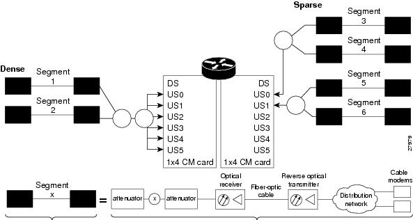
Upstream Segments and Combiner Groups
The Cisco routers divide a cable plant into downstream channels. Downstream channels contain upstream segments. Each upstream segment typically serves more than one fiber node. Upstream segments can be defined as one of the following:
•
•
Note
Defining sparse segments allows the cable operator to share upstream bandwidth among fiber nodes with fewer subscribers. Defining dense segments allows the cable operator to provide larger upstream bandwidth to fiber nodes with many subscribers.
Figure 17-1 illustrates sparse versus dense segments.
Figure 17-1 Sparse Versus Dense Segment Illustrations
As shown in Figure 17-1, the downstream segment can contain multiple upstream segments. Two fiber nodes can be in one downstream segment but in different upstream segments.
The return path of several fiber nodes can be combined at a single point to form a single RF frequency domain called a combiner group. The CMTS software allows a frequency hop table called a spectrum group to be associated with a combiner group.
Note
Frequency Management Policy
Spectrum management applies a common frequency-management policy to a set of upstream ports to ensure that data is delivered reliably over the cable plant. Cable plant operators must make noise measurements and determine the cable plant's spectrum management policy. Different modulation schemes, upstream frequency techniques, and symbol rates are used based on the cable plant characteristics and the cable interface line card in the chassis.
See the following sections for more information about these topics:
•
•
Noise Impairments
Upstream noise impairments such as signal degradation on cable networks can negatively affect service to subscribers. Two-way digital data signals are more susceptible than one-way signals to stresses in the condition of the HFC network. Degradation in video signal quality might not be noticeable in one-way cable TV service, but when two-way digital signals share the network with video signals, digital signals can be hampered by:
•
•
•
•
•
To adjust your return amplifiers and lasers, follow rigorous plant maintenance procedures documented in the NTSC Supplement on Upstream Transport Issues or appropriate cable plant standard.
Spectrum Groups and Frequency Hopping
We recommend that CMTS administrators configure upstream frequency hopping to counteract long-term, narrowband noise. Cisco CMTS routers support a combination of guided frequency hopping and time-scheduled frequency hopping.
The frequency hop to proactively avoid noise ingress is sometimes called frequency agility. Frequency agility is configured and activated using spectrum groups. Spectrum management supports the creation of a number of cable spectrum groups, allowing multiple upstream ports in a single spectrum group. Each spectrum group defines the table of frequencies to be used in a specific frequency plan. Upstream frequencies can be a fixed single frequency, a single continuous range of frequencies (band), or multiple ranges (or bands) of frequencies.
The cable interface does not operate until you assign a frequency to the upstream, which can be done either by configuring and assigning a spectrum group or assigning a fixed frequency. The spectrum group takes precedence, so if you configure both a spectrum group and a fixed frequency on an upstream, the spectrum group overrides the fixed upstream frequency setting.
From the interface point of view, a spectrum group also represents the set of upstreams connected to the same group of fiber nodes. The spectrum manager software in Cisco routers examines all the RF parameters that have been configured on an upstream to determine whether the upstream frequencies need to be managed together. For example, if you configure a spectrum group with several fixed frequencies, but those frequencies are all within the configured channel width, the spectrum manager software combines the frequencies into a single band.
The upstream ports use the spectrum group to determine which frequencies are available if frequency hopping is needed to deal with noise or other path impairments. The types of frequency hopping techniques are guided, time-scheduled, and combined guided and time-scheduled. See the "Frequency Hopping Capabilities" section for more information on the types of frequency hopping techniques.
Note
Guidelines for Spectrum Management
In general, when defining your spectrum, use the following guidelines:
•
•
•
•
•
•
•
Guided and Scheduled Spectrum Management
Guided and scheduled spectrum management constitutes a set of basic features for all currently supported cable interface line cards. These features are considered basic because they are available for all cable interfaces, and constitute the elementary, cornerstone features upon which the intelligent and advanced spectrum management features are built.
See the following sections for more information about each feature:
•
•
Traffic Shaping
Traffic shaping basically uses queues to limit data surges that can congest a network. The data is buffered and then sent into the network in regulated amounts to ensure that the traffic fits within the expected traffic envelope for the particular connection.
Traffic shaping reduces the chance that information must be retransmitted to hosts on the cable plant. When cable modems (CMs) have rate limits established, the CMTS typically drops data packets to enforce the rate limit. Dropping packets from the requesting CM causes the host sending the information to retransmit its information, which wastes bandwidth on the network. If both hosts sending and requesting information are on the cable plant, the upstream bandwidth is wasted as well.
Traffic shaping allows the CMTS to perform upstream and downstream rate limiting on the DOCSIS upstream and downstream channels. Rate limiting restricts the data rate to and from a CM; the MAC scheduler supports traffic-shaping capabilities for downstream and upstream traffic. Rate limiting ensures that no single CM consumes all of the channel bandwidth and allows a CMTS administrator to configure different maximum data rates for different subscribers. Subscribers requiring higher peak rates and willing to pay for higher rates can be configured with higher peak rate limits in their CM DOCSIS configuration file over regular subscribers, who pay less and get lower rate limits.
Each time a packet belonging to a flow is transmitted on an output channel, the token-bucket policer function checks the rate limit status of the flow, passing the following parameters:
•
•
•
•
•
•
•
Every flow has its own shaping buffer where rate-exceeded packets are typically held back in first-in/first-out (FIFO) order for later transmission.
Tip
Upstream Traffic Shaping
Upstream traffic shaping allows the CMTS to perform rate limiting on a DOCSIS upstream channel. The upstream traffic shaping feature delays the scheduling of the upstream packet, which in turn, causes the packet to be buffered on the cable modem device, instead of being dropped. This allows the user TCP/IP stack to pace the application traffic appropriately and approach throughput commensurate with the subscriber's defined quality of service (QoS) levels. Upstream traffic shaping enables the CMTS to enforce the peak upstream rate for each CM without degrading overall TCP performance for the subscriber CMs.
When you do not enable the shaping option for upstream rate limiting, the CMTS upstream-rate-policing code drops bandwidth requests from cable modems that are found to have exceeded their configured-peak-upstream rate (using different local drop policies). The effect of bandwidth requests (eventually upstream packets) being dropped causes degraded throughput performance of window-based protocols (like TCP) for these rate-exceeded modems because of the timeouts and retransmits that follow.
Upstream grant shaping is on a per-CM (service identifier-SID) basis. The grant shaping feature is a configurable option for the current upstream token-bucket rate-limiting algorithm.
A traffic shaping feature is restricted QoS class assignment, which allows a CMTS administrator to override the class of service provisioned for a CM. When this feature is enabled, the user-defined QoS profile is enforced on the CM attempting to register with the CMTS, regardless of the CM's provisioned class of service. Use the cable qos profile command to configure a QoS profile.
Note
For configuration task information on upstream traffic shaping, refer to the "Enabling Upstream Rate Limiting" section.
Downstream Traffic Shaping
The CMTS supports basic downstream traffic shaping by effecting data rate limiting on a per-modem basis. A downstream traffic shaping feature called downstream rate limiting with type of service (ToS) bits extends that capability by allowing the CMTS administrator to configure the ToS byte to calculate the data rate for a specified flow.
Downstream rate limiting with ToS bits enables you to partition downstream traffic for a CM into multiple classes of service and multiple data rates by using the three precedence bits in the ToS byte in the IP header to specify a class of service assignment for each packet. Those packets with the precedence bit set in the ToS field are given higher priority. Using the ToS byte, you can calculate the data rate for a specified flow, in addition to the data rate configured on a per-CM basis. By specifying a maximum data rate for a particular ToS, you can override the common maximum downstream data rate.
The administrator can override the maximum common downstream data rate limits by configuring the ToS byte.
Note
Frequency Hopping Capabilities
Noise in the upstream transmission line, that is from the consumer to the service provider, can degrade data transmission from the subscriber's home. If the noise impairment is of substantial duration, it may cause the cable modem to temporarily lose communication with the headend facility. As a contingency plan, the multiple service operators (MSOs) can reserve multiple channels or upstream frequencies for their subscribers. If one channel suffers too much interference, the CMTS requests that the cable modems "hop" to another channel.
To provide frequency hopping capability, Cisco CMTS routers contain a spectrum manager that continuously monitors the noise in unused upstream channels. If the CNR reaches an unacceptable level on a particular channel, the spectrum manager automatically assigns a new upstream channel to the cable modem using that channel.
Cisco CMTS routers support the following techniques for upstream frequency hopping when the frequency band in use is not clean:
•
•
•
Note
Time-scheduled and guided hopping techniques are independent concepts:
•
•
•
You can configure and activate frequency hopping by using spectrum groups. You can create up to 40 cable spectrum groups, each containing multiple upstream ports. The configured channel width is used for each upstream frequency.
After you have created one or more spectrum groups for your cable network, you can add characteristics to them, providing you with more definitive control over frequency usage and frequency hopping.
You can configure hopping thresholds. For example, the frequency hop threshold percentage method prevents a single failing cable modem from affecting service to other working cable modems. As long as a high enough threshold is configured, the system does not hop endlessly due to a single cable modem failing to respond to 90 percent of its station maintenance (keepalive) messages.
You can also configure the minimum period between frequency hops, with a default setting of 300 seconds. If the destination channel is expected to be impaired, you can reduce the minimum period between frequency hops to a small value, such as 10 seconds. This allows the frequency hop to continue more rapidly until a clear channel is found. If excessive frequency hop is an issue, you can increase the minimum period between hops.
To configure different techniques of frequency hopping, see the "Creating and Configuring Spectrum Groups" section.
Note
Guided Frequency Hopping
Guided frequency hopping is called "guided" because the frequency hopping uses the frequencies that are specified in the spectrum group, which can be either a set of discrete frequencies or a band. The cable interface line cards that support guided frequency hopping do not have a "look-ahead" mechanism that would allow them to determine the quality of the new frequency or band ahead of time, which is why previous documents referred to this as blind hopping. Because of this, though, the cable interface does not need to perform any search on the new potential frequencies, so the switching time between frequencies is only approximately 20 milliseconds.
You can specify some rules the system uses when hopping to another frequency when the frequency band in use is not clean. You can assign explicit frequency subbands and associated input power levels in a spectrum group. All cable modems then on the upstream port migrate to the next frequency with an assigned input power level. The number of lost station management messages exceeding a configured threshold can initiate an upstream channel frequency reassignment. For example, you can specify a frequency hop based on lost station management messages that exceed a threshold. The default threshold may be 10 to 20 percent depending on the Cisco IOS release. The frequency change occurs rapidly without data loss and with minimal latency.
Take care to reduce the spectrum allocation when it is used with small channel widths. Otherwise, there will be a large number of upstream channel slots. For example, if the allocation is from 20.0 to 28.0 MHz and an upstream port has its channel width set to 0.2 MHz, there are 40 possible slots for that channel width. Guided frequency hopping can require a long time to find the clean slot, because it tries each available slot, one at a time, for several seconds during each try.
Time-Scheduled Frequency Hopping
You can specify upstream channel frequency reassignment based on a configured time of every day or of a specific day of the week. If your cable plant has an upstream noise characteristic on a weekly cycle, use time-scheduled spectrum allocation. With a time-scheduled policy, a single frequency becomes valid at any given time.
Dynamic Upstream Modulation (SNR-Based)
The basic Dynamic Upstream Modulation feature is supported on all Cisco cable interface line cards beginning with Cisco IOS Release 12.1(3a)EC1, Cisco IOS Release 12.2(4)BC1b, and later releases. This section describes the operation of this feature, which is based on evaluating the signal-to-noise ratio (SNR) of an upstream.
Note
Feature Overview
Cisco cable interface line cards monitor the SNR values and the forward error correction (FEC) counters in the active return path of each upstream port. The Dynamic Upstream Modulation feature determines whether upstream channel signal quality can support the modulation scheme configured, and adjusts to the most robust modulation scheme when necessary. When return path conditions improve, this feature returns the upstream channel to the higher modulation scheme that includes the modulation profile.
A modulation profile is a collection of six burst profiles that are sent out in a UCD message to configure modem transmit parameters for the upstream message types: request, request/data, initial maintenance, station maintenance, short grant, and long grant. Dynamic Upstream Modulation adjusts the modulation profiles of an upstream channel based on upstream signal quality.
Dynamic Upstream Modulation can be configured on interfaces with fixed upstream frequencies or on interfaces with assigned spectrum groups. For information on commands to configure Dynamic Upstream Modulation, see the "Configuring Dynamic Upstream Modulation (SNR-Based)" section.
The following examples show two different configurations of the Dynamic Upstream Modulation feature, using two and three modulation profiles.
Example Showing Dynamic Upstream Modulation Using Two Modulation Profiles
You can configure the Dynamic Upstream Modulation feature on the Cisco CMTS router using the following primary and secondary modulation profiles:
•
•
We recommend that the primary profile use 64-QAM or QAM-16 modulation and the secondary use QPSK, but this is optional. Both modulation profiles can be either QPSK or QAM. It is not mandatory that one is QAM and the other QPSK, but modulation profile switchover is tied to the QAM and QPSK thresholds.
Example Showing Dynamic Upstream Modulation Using Three Modulation Profiles
You can configure the Dynamic Upstream Modulation feature on the Cisco CMTS router using the following primary, secondary, and tertiary modulation profiles:
•
•
•
We recommend that the primary profile use 64-QAM modulation, the secondary profile use 16-QAM, and the tertiary profile uses QPSK, but this is optional. The modulation profiles can be either QPSK or QAM. It is not mandatory that one is QPSK and the other two are QAM, but modulation profile switchover is tied to the QAM and QPSK thresholds.
Tip
Criteria for Switching Modulation Profiles
The Dynamic Upstream Modulation feature uses the following criteria to determine whether it should switch from the primary modulation profile (the more bandwidth-efficient, but less robust profile) to the other modulation profiles (more robust, but less bandwidth-efficient profile):
The modulation switch from the primary profile (high performance) to the secondary profile (mid-level performance) uses the following criteria:
•
Before switching back to the primary profile from the secondary profile, the following criteria must be satisfied:
•
The modulation switch from the secondary profile (mid-level performance) to the tertiary profile (most robust) uses the following criteria:
•
Before switching back to the secondary profile from the tertiary profile, the following criteria must be satisfied:
•
The modulation switch from the primary profile to the tertiary profile uses the following criteria:
•
If the only problem is that the upstream is experiencing a large number of uncorrectable errors, then a situation could occur where the router continues to switch back and forth between profiles. The uncorrectable errors occur with the primary profile, so the router switches to the secondary profile. The secondary profile does not experience any problems, so the router switches back to the primary profile. But the uncorrectable errors reoccur and the router switches back to the secondary profile, and this cycle continues indefinitely.
To avoid this problem, make sure that the cable plant is capable of supporting the modulation scheme being used in the primary profile (for example, 64-QAM). If you cannot guarantee successful operation on an upstream using this modulation scheme, then you should select a primary profile that uses a more bandwidth-efficient set of burst parameters (such as QPSK). The Cisco IOS software includes predefined modulation profiles that can be used for the primary, secondary, and tertiary profiles.
Input Power Levels
Upstream input power level modifications were made in Cisco IOS Releases 12.0(6)SC, 12.1(1), 12.1(1)T, 12.1(2)EC1, and 12.2(4)BC1b. The input power level, power-level-dBmV, is an option in the cable spectrum-group command. The option allows you to specify the expected upstream input power levels on the upstream receivers on the CMTS when the cable modems are hopping from one fixed frequency to another or from one band to another. Each upstream frequency has an associated upstream input power level in dBmV. The power level is the modem transmit power that each spectrum group can use when an upstream frequency change is necessary. The input power level may be set at the time of the frequency hop.
Specifying an input power level is done so that the cable modems do not have to increase or decrease their transmit power with every hop. The cable operator can perform minor power equalizations as a function of frequency. The valid range is -10 to 10dBmV. The power level value should be changed only if you want to change the power level as part of spectrum management. Some cable plants may want to change only the input power level, and not the frequency, on a daily time schedule.
For information on how to configure input power levels, see the "Configuring and Assigning Spectrum Groups" section.
Intelligent and Advanced Hardware-Based Spectrum Management
Several cable interface line cards include hardware-based spectrum management features that provide enhancements to the basic features supported by the other Cisco cable interface line cards. (See Table 17-2 for a list of supported cable interface line cards and required Cisco IOS releases.)
Intelligent Spectrum Management Enhancements
The following features are part of the intelligent spectrum management feature set:
•
•
•
•
•
•
•
•
•
•
Advanced Spectrum Management Support Using the Cisco uBR10-MC5X20S/U/H BPE
The advanced spectrum management features were introduced on the Cisco uBR10-MC5X20S/U/H BPE as a software-only upgrade. These enhancements are supported on additional line cards on the Cisco IOSReleases that are shown in Table 17-2.
The following additional features are part of the advanced spectrum management feature set:
•
•
•
Note
•
–
This logic can be expressed as the following formula:
[(CNR <= threshold) AND (SNR <= threshold)] AND
[ (correctable FEC >= threshold) OR (uncorrectable FEC >= threshold)]
This approach helps avoid unneeded channel changes due to transient noise problems that do not actually cause any errors in the data stream. The channel changes only when noise both affects the CNR and SNR of the upstream and generates an unacceptable number of FEC errors in the data. If you want channel changes to occur only in response to the CNR, you can set the SNR threshold and the FEC error threshold values to zero.
Separate CNR threshold values are configured for the primary and secondary modulation profiles. When the upstream has moved to the secondary modulation profile, further frequency hopping or channel width changes occur only when the CNR value and the SNR value falls below the user-defined threshold value for the secondary profile.
Note
•
•
•
Note
Benefits
The spectrum management features provided on the Cisco CMTS router platforms provide several key system benefits:
•
•
•
•
•
•
Guided and Scheduled Spectrum Management Benefits
The following summarizes the specific benefits of the guided and scheduled spectrum management features that are supported for all Cisco CMTS router platforms.
Upstream Traffic Shaping
The CMTS can buffer the grants for rate-exceeded modems. This grant buffering at the CMTS avoids TCP-related timeouts and retransmits, resulting in an improved TCP throughput performance for the rate-exceeded modems. Thus, traffic shaping enables the CMTS to enforce the peak upstream rate for the modem without degrading overall TCP performance for the modem.
Downstream Traffic Shaping
Allows users to configure multiple data rates (defined by the value of the IP precedence bits in the ToS byte) for a given modem. By specifying a maximum data rate for a particular ToS, users can override the common maximum downstream data rate.
Input Power Levels
Allows the cable plant operator to perform minor power level equalization as a function of frequency.
Frequency Hopping Capabilities
Proactively countermeasures upstream noise impairments by assigning a new upstream channel to the cable modem. MSOs can take advantage of this feature especially when they have less than an optimal carrier-to-noise ratio in the upstream frequencies or when their cable plants exhibit random bursts of ingress noise that affect reliability.
Dynamic Upstream Modulation
•
•
•
Intelligent and Advanced Spectrum Management Benefits
The following summarizes the specific benefits of the advanced spectrum management features that are supported on Cisco CMTS routers using supported cable interface line cards.
Dynamic Channel Width Change
•
•
•
Intelligent Frequency Hopping
•
•
•
•
•
•
Dynamic Upstream Modulation
•
•
•
•
•
SNMP Interface
•
•
•
•
•
•
How to Configure Spectrum Management
This section describes the configuration tasks that are most commonly performed when using the spectrum management features on the Cisco CMTS platforms. See the following sections for the configuration tasks that are appropriate for your platform and cable interface line cards.
•
•
Guided and Scheduled Spectrum Management Configuration Tasks
The following tasks configure the guided and scheduled spectrum management features that are supported on all Cisco CMTS platforms:
•
•
•
•
•
•
Enabling Upstream Rate Limiting
Upstream rate limiting allows upstream bandwidth requests from rate-exceeding cable modems to be buffered without incurring TCP-related timeouts and retransmits. This enables the CMTS to enforce the peak upstream rate for each cable modem without degrading overall TCP performance for the subscriber customer premises equipment (CPE) devices. Upstream grant shaping is per SID.
By default, all upstreams are configured for rate limiting that uses the token-bucket policing algorithm with traffic shaping, which enforces strict DOCSIS-compliant rate limiting. If you have previously disabled or reconfigured rate limiting on an upstream, use the following procedure to re-enable rate limiting on that upstream.
SUMMARY STEPS
1.
2.
3.
or
interface cable x/y/z4.
5.
DETAILED STEPS
Step 1
enable
Example:Router> enable
Enables privileged EXEC mode. Enter your password if prompted.
Step 2
configure terminal
Example:Router# configure terminal
Enters global configuration mode.
Step 3
interface cable x/y
orinterface cable x/y/z
Example:Router(config)# interface cable 5/1
Enters interface configuration mode for the specified cable interface.
Step 4
[no] cable upstream usport rate-limit [token-bucket [shaping]]
Example:Router(config-if)# cable upstream 0 rate-limit
Enables rate limiting for the specified upstream port.
•
•
•
Use the no version of this command to disable rate limiting on an upstream, but we do not recommend doing this.
Note
Step 5
end
Example:Router(config-if)# end
Exits interface configuration mode and returns to privileged EXEC mode.
Enabling Downstream Rate Limiting
Downstream rate limiting enables you to use the token-bucket policing algorithm with traffic shaping options or the weighted-discard policing algorithm to buffer, shape, or discard packets that exceed a set bandwidth. Downstream rate limiting is disabled by default.
To enable downstream rate limiting for a downstream port on a Cisco cable interface line card, use the following procedure.
SUMMARY STEPS
1.
2.
3.
or
interface cable x/y/z4.
5.
DETAILED STEPS
Step 1
enable
Example:Router> enable
Enables privileged EXEC mode. Enter your password if prompted.
Step 2
configure terminal
Example:Router# configure terminal
Enters global configuration mode.
Step 3
interface cable x/y
orinterface cable x/y/z
Example:Router(config)# interface cable 5/1
Enters interface configuration mode for the specified cable interface.
Step 4
[no] cable downstream rate-limit [token-bucket [shaping] [granularity msec | max-delay msec | weighted-discard exp-weight]]
Example:Router(config-if)# cable downstream rate-limit
Enables rate limiting on the downstream. You can also specify the following options:
•
•
•
•
•
Note
Step 5
end
Example:Router(config-if)# end
Exits interface configuration mode and returns to privileged EXEC mode.
Creating and Configuring Spectrum Groups
A spectrum group defines the frequencies that an upstream is allowed to use when frequency hopping is done, as well as other parameters that control the frequency hops. When creating and configuring spectrum groups, you can specify the following parameters:
•
–
–
–
•
•
•
•
•
Tip
Restrictions
•
•
To create and configure a spectrum group, use the the following procedure.
SUMMARY STEPS
1.
2.
3.
4.
5.
6.
7.
8.
DETAILED STEPS
Step 1
enable
Example:Router> enable
Enables privileged EXEC mode. Enter your password if prompted.
Step 2
configure terminal
Example:Router# configure terminal
Enters global configuration mode.
Step 3
cable spectrum-group group-number [time day hh:mm:ss] frequency up-freq-Hz [power-level-dBmV]
Example:Router(config)# cable spectrum-group 4 time Monday 12:00:00 frequency 40000000
Creates the spectrum group (if it does not already exist), and adds the specified fixed frequency to the group.
•
•
•
•
Step 4
cable spectrum-group group-number [time day hh:mm:ss] band up-freq-Hz up-freq2-Hz [power-level-dBmV]
Example:Router(config)# cable spectrum-group 4 band 20000000 24000000 13
Creates the spectrum group (if it does not already exist), and adds the specified band of frequencies to the group.
•
•
•
•
Note
Step 5
cable spectrum-group group-number hop period seconds
Example:Router(config)# cable spectrum-group 4 hop period 60
Specifies the minimum time, in seconds, between frequency hops.
•
Note
Step 6
cable spectrum-group group-number hop threshold [percent]
Example:Router(config)# cable spectrum-group 4 hop threshold 25
Specifies the frequency hop threshold for a spectrum group.
•
Step 7
cable spectrum-group group-number shared
Example:Router(config)# cable spectrum-group 4 shared
(Optional) Specifies that the upstream ports in a spectrum group should use a unique upstream frequency.
Step 8
end
Example:Router(config)# end
Exits global configuration mode and returns to privileged EXEC mode.
Assigning a Spectrum Group to One or More Upstream Ports
After a spectrum group has been created and configured, you must assign it to one or more upstream ports before the group's frequency spectrum is used for frequency hopping. You can assign a spectrum group to an upstream in the following ways:
•
•
To assign a spectrum group to one or all upstream ports on an interface, use the following procedure.
SUMMARY STEPS
1.
2.
3.
or
interface cable x/y/z4.
5.
6.
DETAILED STEPS
Step 1
enable
Example:Router> enable
Enables privileged EXEC mode. Enter your password if prompted.
Step 2
configure terminal
Example:Router# configure terminal
Enters global configuration mode.
Step 3
interface cable x/y
orinterface cable x/y/z
Example:Router(config)# interface cable 5/1
Enters interface configuration mode for the specified cable interface.
Step 4
cable spectrum-group group-number
Example:Router(config-if)# cable spectrum-group 4
Assigns the specified spectrum group as the default group for all upstreams on this cable interface. The valid range for group-number is from 1 to 32, or from 1 to 40, depending on the Cisco IOS software release.
Step 5
cable upstream n spectrum-group group-number
Example:Router(config-if)# cable upstream 1 spectrum-group 5
Assigns the specified spectrum group to this individual upstream, overriding any previous assignment that was done for all upstreams on the interface using the cable spectrum-group command.
•
•
Note
Note
Step 6
end
Example:Router(config-if)# end
Exits interface configuration mode and returns to privileged EXEC mode.
Note
Tip
Configuring Shared Spectrum Groups (Fiber Node Groups) for DOCSIS 3.0
Cisco IOS Release 12.3(21)BC, and later releases, support shared spectrum groups, otherwise known as fiber node groups, for DOCSIS 3.0 on the Cisco uBR10012 router. This feature supports shared spectrum groups that cross multiple cable interface line cards on the Cisco uBR10012 router, and shared spectrum groups within a single cable interface line card.
Refer to the following documents on Cisco.com for additional information about configuring fiber node groups on the Cisco CMTS:
•
•
•
Configuring Dynamic Upstream Modulation (SNR-Based)
To use the Dynamic Upstream Modulation feature on cable interface line cards that support only the SNR version of this feature, you must do the following:
1.
2.
3.
4.
Tip
Restrictions
•
•
•
•
•
•
–
–
To create and assign the primary, secondary, and tertiary modulation profiles to an upstream, use the following procedures.
SUMMARY STEPS
1.
2.
3.
4.
or
interface cable x/y/z5.
6.
DETAILED STEPS
Tip
Verifying Frequency Hopping
You can verify frequency hopping on the CMTS either by using the command-line interface (CLI) or by using an RF tone generator.
For Cisco IOS Release 12.3(13a)BC and later releases, two more show commands have been added:
•
•
Verifying Frequency Hopping Using CLI Commands
To verify frequency hopping using CLI commands, use the following procedure:
Step 1
Router# show interface c6/0Cable6/0 is up, line protocol is upHardware is BCM3210 ASIC, address is 000a.13e8.1ca8 (bia 000a.13e8.1ca8)Internet address is 10.20.114.33/27MTU 1500 bytes, BW 27000 Kbit, DLY 1000 usec,Step 2
Router# show interface c6/0 upstream 5Cable6/0: Upstream 5 is upReceived 8 broadcasts, 0 multicasts, 6388105 unicasts0 discards, 0 errors, 0 unknown protocol6388113 packets input, 0 uncorrectable0 noise, 0 microreflectionsTotal Modems On This Upstream Channel : 23 (22 active)Step 3
Router# show cable hop c6/0 upstream 5Upstream Port Poll Missed Min Missed Hop Hop Corr UncorrPort Status Rate Poll Poll Poll Thres Period FEC FEC(ms) Count Sample Pcnt Pcnt (sec) Errors ErrorsCable6/0/U5 16.816 Mhz 1000 0 10 0% 20% 25 0 0Step 4
Router# show cable hop c6/0/0 upstream 0 historyF = Frequency Hop, M = Modulation Change, C = Channel Width ChangeUpstream Action Chg Chg ActionPort Time Code From To ReasonC6/0/0 U0 Feb 20 12:21:29 M 142 141 SNR 28>=28 CFEC 0<=3 UnCFEC 0<=1Feb 20 12:09:08 F 0.000 24.000 Configuration changed
Note
Step 5
Router# show cable hop c6/0/0 upstream thresholdUpstream SNR(dB) CNR(dB) CorrFEC% UncorrFEC% MissedSM%Port Val Thre1 Thre2 Val Thre1 Thre2 Pcnt Thre Pcnt Thre Pcnt ThreCa6/0/0/U0 27 25 15 39 35 25 0 3 0 1 75 75Ca6/0/0/U1 31 25 15 51 35 25 0 3 0 1 90 75Ca6/0/0/U2 -- 35 25 -- 35 25 0 3 0 1 0 75Ca6/0/0/U3 -- 35 25 -- 35 25 0 3 0 1 0 75Step 6
Router# test cable hop c6/0 upstream 52w0d: %UBR7200-5-USFREQCHG: Interface Cable6/0 Port U5, frequency changed to 15.760 MHzRouter# test cable hop c6/0 upstream 52w0d: %UBR7200-5-USFREQCHG: Interface Cable6/0 Port U5, frequency changed to 26.832 MHzVerifying Frequency Hopping Using an RF Tone Generator
To verify frequency hopping using an RF tone generator, first verify that the upstream is performing properly. Then inject a tone to the upstream port at the current upstream frequency and cable modem power level.
For example, if the upstream frequency is 22.4 MHz, inject a 22.4-MHz tone at approximately the same power level as the modem. If the power level at the modem is 40 dBmV, set the tone power to 40 dBmV. The interfering carrier should shut down the channel and cause the frequency to change to the next configured value (such as 24.0 MHz).
If you do not have an RF tone generator, use another line card and modem that carries traffic. Connect the upstream to the same combiner group, and use the data carrier as an interfering signal by setting it to the same frequency. For example, to test frequency hopping on c3/0, install c4/0 and connect both upstreams together using a combiner. If the upstream frequency of c3/0 is 22.4 MHz, set c4/0 to 22.4 MHz while c4/0 is carrying traffic. This should force c3/0 to change the frequency to the next configured value.
The comparison of the number of errors versus the number of error-free packets is a measure of the link quality. The percentage of errors should be less than one percent.
Troubleshooting Spectrum Group Characteristics
To troubleshoot the configuration, make sure that you entered a valid spectrum group number, time, frequency, and input power level. Also, when defining your spectrum, use the following guidelines:
•
•
•
•
•
Intelligent and Advanced Spectrum Management Configuration Tasks
The following sections describe the configuration tasks that are needed to configure a Cisco uBR7200 series router or Cisco uBR10012 router for the intelligent and advanced spectrum management features that are available with the the Cisco uBR-MC16U/X, Cisco uBR-MC28U/X, and Cisco uBR10-MC5X20S/U/H cable interface line cards.
•
•
•
•
Configuring and Assigning Spectrum Groups
You must create and configure a spectrum group before you can use the intelligent and advanced spectrum management features. These procedures are the same as those used for guided and scheduled spectrum management, which are given in the following sections:
•
•
After the spectrum groups have been configured and assigned to upstreams, the Cisco IOS software automatically uses the advanced frequency hopping algorithms on the cable interface line cards that support it.
Note
Configuring Dynamic Upstream Modulation (CNR-Based)
Configuring the CNR-based version of the Dynamic Upstream Modulation feature is similar to configuring the SNR-version of this feature:
1.
2.
Tip
3.
After the modulation profiles have been created and assigned to upstreams, the Cisco IOS software automatically uses the advanced CNR-based version of the Dynamic Upstream Modulation feature on the cable interface line cards that support it.
Restrictions
•
•
cable modulation-profile n short 6 75 6 8 16qam scrambler 152 no-diff 144fixed uw16cable modulation-profile n long 8 220 0 8 16qam scrambler 152 no-diff 160fixed uw16
Note
•
•
To assign the primary and secondary profiles to an upstream, use the following procedure.
SUMMARY STEPS
1.
2.
3.
4.
or
interface cable x/y/z5.
6.
DETAILED STEPS
Configuring Proactive Channel Management
The cable interface line cards that support the advanced spectrum management features can be configured with the following parameters so as to fine-tune the operation of proactive channel management on the cards' upstreams:
•
•
•
These parameters all have default settings, so you do not need to perform this procedure unless you want to change these parameters to better match the characteristics of your physical plant.
A major exception to this is if you are using only one modulation profile and are using a software release prior to Cisco IOS Release 12.2(8)BC2. In these releases, a frequency hop would occur if just one of the measured values (CNR value, correctable FEC counter, or uncorrectable FEC counter) crosses the configured threshold value. Because of this, if you are using only one modulation profile (QPSK) with one of these software releases, you might need to reduce the CNR threshold value and increase the correctable FEC error value to prevent undesired frequency hopping.
Note
To configure these parameters, use the following procedure.
Note
Configuring Proactive Channel Management for Releases Prior to 12.3(13a)BC
SUMMARY STEPS
1.
2.
3.
or
interface cable x/y/z4.
or
cable upstream n hop-priority modulation frequency channel-width
or
cable upstream n hop-priority frequency channel-width modulation5.
6.
7.
DETAILED STEPS
Step 1
enable
Example:Router> enable
Enables privileged EXEC mode. Enter your password if prompted.
Step 2
configure terminal
Example:Router# configure terminal
Enters global configuration mode.
Step 3
interface cable x/y
orinterface cable x/y/z
Example:Router(config)# interface cable 5/1
Enters interface configuration mode for the specified cable interface.
Step 4
cable upstream n hop-priority frequency modulation channel-width
or
cable upstream n hop-priority modulation frequency channel-width
or
cable upstream n hop-priority frequency channel-width modulation
Example:Router(config-if)# cable upstream 0 hop-priority frequency channel-width modulation
Specifies the priority of the three types of corrective actions (modulation, frequency, and channel-width) to be taken when the noise for the upstream exceeds the threshold specified for the current modulation profile. The default priority is frequency, modulation, and channel-width.
•
Note
Step 5
cable upstream n threshold cnr-profile1 threshold1-in-dB cnr-profile2 threshold2-in-dB corr-fec fec-corrected uncorr-fec fec-uncorrected
Example:Router(config-if)# cable upstream 5 threshold cnr-profile1 20 cnr-profile2 10 corr-fec 5
uncorr-fec 1
#
Specifies the CNR threshold and FEC values for the upstream and its two modulation profiles.
•
•
•
•
•
Note
Step 6
cable upstream n channel-width first-choice-width [last-choice-width]
Example:Router(config-if)# cable upstream 0 channel-width 800000 800000
Specifies the range of allowable channel widths that can be used when ingress noise conditions require changing the channel width. The upstream begins with the first-choice channel width and decreases in half until it hits the secondary channel width.
•
–
–
–
–
–
–
•
Note
Step 7
end
Example:Router(config-if)# end
Exits interface configuration mode and returns to privileged EXEC mode.
Configuring Proactive Channel Management for Release 12.3(13a)BC
SUMMARY STEPS
1.
2.
3.
or
interface cable x/y/z4.
or
cable upstream n hop-priority modulation frequency channel-width
or
cable upstream n hop-priority frequency channel-width modulation5.
6.
7.
8.
9.
10.
11.
DETAILED STEPS
Step 1
enable
Example:Router> enable
Enables privileged EXEC mode. Enter your password if prompted.
Step 2
configure terminal
Example:Router# configure terminal
Enters global configuration mode.
Step 3
interface cable x/y
orinterface cable x/y/z
Example:Router(config)# interface cable 5/1
Enters interface configuration mode for the specified cable interface.
Step 4
cable upstream n hop-priority frequency modulation channel-width
or
cable upstream n hop-priority modulation frequency channel-width
or
cable upstream n hop-priority frequency channel-width modulation
Example:Router(config-if)# cable upstream 0 hop-priority frequency channel-width modulation
Specifies the priority of the three types of corrective actions (modulation, frequency, and channel-width) to be taken when the noise for the upstream exceeds the threshold specified for the current modulation profile. The default priority is frequency, modulation, and channel-width.
•
Note
Step 5
cable upstream n threshold cnr-profiles threshold1-in-dB threshold2-in-dB
Example:Router(config-if)#cable upstream 2 threshold cnr-profiles 23 14
(Optional) Specifies the CNR threshold and FEC values for the upstream and its two modulation profiles.
•
•
•
Step 6
cable upstream n upstream threshold snr-profiles threshold1-in-dB threshold2-in-dB
Example:Router(config-if)# cable upstream 2 threshold snr-profiles 23 14
(Optional) Specifies the SNR threshold and FEC values for the upstream and its two modulation profiles.
•
•
•
Step 7
cable upstream n threshold hysteresis
hysteresis-in-dB
Example:Router(config-if)# cable upstream 2 threshold hysteresis 3
(Optional) Specifies the hysteresis value to be used in conjunction with the dynamic modulation upgrade thresholds.
•
Step 8
cable upstream n threshold corr-fec corrfec-threshold
Example:Router(config-if)# cable upstream 5 threshold corr-fec 5
(Optional) Specifies the CNR threshold and FEC values for the upstream and its two modulation profiles.
•
•
Step 9
cable upstream n threshold uncorr-fec uncorrfec-threshold
Example:Router(config-if)# cable upstream 5 threshold uncorr-fec 1
(Optional) Specifies the CNR threshold and FEC values for the upstream and its two modulation profiles.
•
•
Note
Step 10
cable upstream n channel-width first-choice-width [last-choice-width]
Example:Router(config-if)# cable upstream 0 channel-width 800000 800000
(Optional) Specifies the range of allowable channel widths that can be used when ingress noise conditions require changing the channel width. The upstream begins with the first-choice channel width and decreases in half until it hits the secondary channel width.
•
–
–
–
–
–
–
•
Note
Step 11
end
Example:Router(config-if)# end
Exits interface configuration mode and returns to privileged EXEC mode.
Verifying the Spectrum Management Configuration
Follow the steps given below to verfiy the spectrum management configuration.
Step 1
Router# show running-configStep 2
Router# show cable modulation-profileTo display the configuration for a specific modulation profile, add the profile number to the show cable modulation-profile command in privileged EXEC mode:
Router# show cable modulation-profile 6Step 3
Router# show controllers c6/0 upstreamCable6/0 Upstream 0 is administratively downFrequency not set, Channel Width 1.600 MHz, QPSK Symbol Rate 1.280 MspsSpectrum Group is unassignedCNR - Unknown - no modems online.Nominal Input Power Level 0 dBmV, Tx Timing Offset 0Ranging Backoff automatic (Start 0, End 3)Ranging Insertion Interval automatic (60 ms)Tx Backoff Start 0, Tx Backoff End 4Modulation Profile Group 1Concatenation is enabledFragmentation is enabledpart_id=0x3137, rev_id=0x03, rev2_id=0xFFnb_agc_thr=0x0000, nb_agc_nom=0x0000Range Load Reg Size=0x58Request Load Reg Size=0x0EMinislot Size in number of Timebase Ticks is = 8Minislot Size in Symbols = 64Bandwidth Requests = 0x0Piggyback Requests = 0x0Invalid BW Requests= 0x0Minislots Requested= 0x0Minislots Granted = 0x0Minislot Size in Bytes = 16Map Advance (Dynamic) : 2180 usecsUCD Count = 0DES Ctrl Reg#0 = C000C043, Reg#1 = 0Cable6/0 Upstream 1 is upFrequency 25.008 MHz, Channel Width 1.600 MHz, 16-QAM Symbol Rate 1.280 MspsSpectrum Group 1, Last Frequency Hop Data Error: NO(0)MC16S CNR measurement - 45 dBNominal Input Power Level 0 dBmV, Tx Timing Offset 2811Ranging Backoff automatic (Start 0, End 3)Ranging Insertion Interval automatic (60 ms)Tx Backoff Start 0, Tx Backoff End 4Modulation Profile Group 1Concatenation is enabledFragmentation is enabledpart_id=0x3137, rev_id=0x03, rev2_id=0xFFnb_agc_thr=0x0000, nb_agc_nom=0x0000Range Load Reg Size=0x58Request Load Reg Size=0x0EMinislot Size in number of Timebase Ticks is = 8Minislot Size in Symbols = 64Bandwidth Requests = 0x12Piggyback Requests = 0x5Invalid BW Requests= 0x0Minislots Requested= 0xFAMinislots Granted = 0xFAMinislot Size in Bytes = 32Map Advance (Dynamic) : 2454 usecsUCD Count = 230DES Ctrl Reg#0 = C000C043, Reg#1 = 0Dynamic Services Stats:DSA: 0 REQs 0 RSPs 0 ACKs0 Successful DSAs 0 DSA FailuresDSC: 0 REQs 0 RSPs 0 ACKs0 Successful DSCs 0 DSC FailuresDSD: 0 REQs 0 RSPs0 Successful DSDs 0 DSD FailuresDCC: 0 REQs 0 RSPs 0 ACKs0 Successful DCCs 0 DCC Failures
Note
Step 4
Router# show cable hopUpstream Port Poll Missed Min Missed Hop Hop Corr UncorrPort Status Rate Poll Poll Poll Thres Period FEC FEC(ms) Count Sample Pcnt Pcnt (sec) Errors ErrorsCable3/0/U0 20.800 Mhz 105 0 20 0% 25% 45 1 4Cable3/0/U1 20.800 Mhz 105 0 48 0% 25% 45 2 19Cable3/0/U2 23.120 Mhz 105 0 45 0% 25% 45 0 5Cable3/0/U3 22.832 Mhz 105 0 26 0% 25% 45 0 6Cable3/0/U4 22.896 Mhz 105 0 43 0% 25% 45 0 7Cable3/0/U5 23.040 Mhz 105 0 54 0% 25% 45 1 3Cable4/0/U0 22.896 Mhz 117 0 26 0% 25% 45 0 2Cable4/0/U1 23.168 Mhz 117 0 87 0% 25% 45 4 2Cable4/0/U2 22.896 Mhz 117 0 23 0% 25% 45 1 0Cable4/0/U3 20.800 Mhz 117 0 54 0% 25% 45 0 0Cable4/0/U4 22.928 Mhz 117 0 22 0% 25% 45 0 1Cable4/0/U5 22.960 Mhz 117 0 0 ----- 25% 45 0 0Step 5
Router# show cable hop c8/1/1 u0 historyF = Frequency Hop, M = Modulation Change, C = Channel Width ChangeUpstream Action Chg Chg ActionPort Time Code From To ReasonC8/1/1 U0 Feb 20 12:21:29 M 142 141 SNR 28>=28 CFEC 0<=3 UnCFEC 0<=1Feb 20 12:09:08 F 0.000 24.000 Configuration changedStep 6
Router# show cable hop c8/1/1 u0 thresholdUpstream SNR(dB) CNR(dB) CorrFEC% UncorrFEC% MissedSM%Port Val Thre1 Thre2 Val Thre1 Thre2 Pcnt Thre Pcnt Thre Pcnt ThreC8/1/1 u0 33 23 14 60 25 15 0 1 0 2 0 50Step 7
Router# show cable spectrum-groupGroup Frequency Upstream Weekly Scheduled Power SharedNo. Band Port Availability Level Spectrum(Mhz) From Time: To Time: (dBmV)1 20.000-21.600 0 No1 22.000-24.000 0 No1 20.784 [1.60] Cable3/0 U0 01 20.784 [1.60] Cable3/0 U1 01 23.120 [1.60] Cable3/0 U2 01 22.832 [1.60] Cable3/0 U3 01 22.896 [1.60] Cable3/0 U4 01 23.024 [1.60] Cable3/0 U5 01 23.152 [1.60] Cable4/0 U1 01 22.896 [1.60] Cable4/0 U0 01 22.896 [1.60] Cable4/0 U2 01 20.784 [1.60] Cable4/0 U3 01 22.928 [1.60] Cable4/0 U4 01 22.960 [1.60] Cable4/0 U5 0Step 8
Router# show cable modem 5.100.1.94 cnrMAC Address IP Address I/F MAC Prim snr/cnrState Sid (dB)0018.689c.17b8 5.100.1.94 C7/0/0/U1 online 428 36.12
Note
Monitoring Spectrum Management
You can use Cisco IOS CLI commands to monitor spectrum management activity on the Cisco CMTS. If you are using Cisco IOS Release 12.2(8)BC2 or later 12.2 BC releases, you can also use SNMP to monitor the spectrum management activity. See the following sections for more information:
Note
Using CLI Commands
The following commands provide information on the spectrum condition of an upstream:
Note
Using SNMP
You can use SNMP to monitor the spectrum management activity. The SNMP manager can be a graphically-based SNMP manager such as CiscoView or the Cable Broadband Troubleshooter (Release 3.0 or later).
The CISCO-CABLE-SPECTRUM-MIB has been enhanced to provide this SNMP support using the following MIB attributes:
ccsSNRRequestTable
Table 17-4 lists the attributes in the ccsSNRRequestTable table, which contains the CNR measurements that are made for individual cable modems on an upstream.
ccsSpectrumRequestTable
Table 17-5 lists the attributes for each entry in the ccsSpectrumRequestTable table, which is used to obtain the spectrum profile for a particular cable modem or to obtain the background SNR for an entire upstream.
ccsSpectrumDataTable
Table 17-6 lists the attributes in each entry of the ccsSpectrumDataTable table, which contains the results for a spectrum request.
Note
ccsUpSpecMgmtTable
Table 17-7 lists the attributes in the ccsUpSpecMgmtTable table, which provides an entry describing each frequency hop.
ccsHoppingNotification
Table 17-8 describes the attributes contained in the notification that is sent after each frequency hop.
Configuration Examples
This section provides the following configuration examples:"
•
•
•
•
•
•
Upstream Traffic Shaping and Rate Limiting Examples
Upstream rate limiting is enabled by default in the Cisco CMTS router, so the cable upstream rate-limit command does not appear in the router's configuration file. To determine if upstream rate limiting is configured and activated, enter the show running-config command and look for the cable interface configuration information.
If upstream rate limiting is disabled, "no cable upstream rate-limit" appears in the output. You can also perform the following tasks to verify that rate limiting is enabled on the upstream channel:
Step 1
Use a regular rate-limiting algorithm on the upstream without rate shaping and note the drops of the excess bandwidth requests from this cable modem when it exceeds its peak upstream rate.
Use the show interface cx/y sid counters command to see the bandwidth request drops. Verify that the upstream rate received by that modem is less than its configured peak rate due to the timeouts and backoffs produced by the drop in bandwidth requests. Enter the show interface cx/y sid command to see the input rate at the CMTS in bps.
Step 2
Step 3
Let the pings run for a period to let averages at the CMTS settle; then view the upstream rate received by this single modem. Use the show interface cx/y command and see the input rate in bps. This value should be close to the modem's peak upstream rate. Also note the drop counts for the modem's SID by using the show interface sid counters command, and verify that the CMTS no longer drops the bandwidth requests from the cable modem.
The bandwidth request drop count (from the previous nonshaping test) remains unchanged when upstream rate shaping is used, indicating that the CMTS is actually shaping (buffering) the grants for the modem. Verify that the input rate at the CMTS (from the single rate-exceeded CM) stabilizes close to the configured peak rate of 128 Kbps.
Perform these steps if you are having difficulty with verification:
•
•
•
•
•
Configuring the Low-Peak-Rate Limit Example
Router# show cable modemInterface SID Online Timing Receive QoS IP address MAC addressState Offset PowerCable3/0/U0 1 online 3564 0.00 6 1.11.53.102 0010.7b6b.7235Router# show cable qos profile 6Service Prio Max Guarantee Max Max tx TOS TOS Create Bclass upstream upstream downstream burst mask value by privbandwidth bandwidth bandwidth enab6 7 128000 100000 4000000 0 0x0 0x0 management yesApplying the Rate-Limiting Algorithm Without Rate Limiting Example
Router(config-if)# cable upstream 0 rate-limitRouter# ping ipTarget IP address:1.11.53.100Repeat count [5]:100000Datagram size [100]:10000Timeout in seconds [2]:Extended commands [n]:Sweep range of sizes [n]:Type escape sequence to abort.Sending 100000, 10000-byte ICMP Echos to 1.11.53.100, timeout is 2 seconds:!.!.!!!.!!.!.!!!.!!.!.!!!.!!.!.!!!.!!.!.!!!.!!.!.!!!.!!.!.!!!.!!.!.!!!.!!.!.!!!.!!.!.!!!.!!.!.!!!.!!.!.!!!.!!.!.!!!.!!.!.!!!.!!.!.!!!.!!.!.!!!.!!.!.!!!.!!.!.!!!.!!.!.!!!.!!.!.!!!.!!.!.!!!.!!.!.!!!.!!.!.!!!.!!.!.!!!.!!.!.!!!.!!.!.!!!.!!.!.!!!.!!.!.!!!.!!.!.!!!.!!.!.!!!.!!.!.!!!.!!!!.!.!!!.!!.!.!!!.!!.!.!!!.!!.!.!!!.!!.!.!!!.!!.!.!!!.!!.!.!!!.!!.!.!!!.!!.!.!!!.!!.!.!!!.!!.!.!!!Router# show interface c3/0 sid 1 countersSid Inpackets Inoctets Outpackets Outoctets Ratelimit RatelimitBWReqDrop DSPktDrop1 67859 99158800 67570 98734862 2579 0Router# show interface c3/0Cable3/0 is up, line protocol is upHardware is BCM3210 ASIC, address is 0009.4553.0061 (bia 0009.4553.0061)Internet address is 1.11.53.100/27MTU 1500 bytes, BW 27000 Kbit, DLY 1000 usec,reliability 255/255, txload 1/255, rxload 1/255Encapsulation MCNS, loopback not set, keepalive not setARP type:ARPA, ARP Timeout 04:00:00Last input 00:00:00, output 00:00:00, output hang neverLast clearing of "show interface" counters neverQueueing strategy:fifoOutput queue 0/40, 0 drops; input queue 0/75, 0 drops5 minute input rate 95000 bits/sec, 9 packets/sec5 minute output rate 82000 bits/sec, 7 packets/sec70093 packets input, 100855618 bytes, 4569 no bufferReceived 992 broadcasts, 0 runts, 0 giants, 0 throttles3 input errors, 0 CRC, 0 frame, 0 overrun, 0 ignored, 0 abort68477 packets output, 100193806 bytes, 0 underruns0 output errors, 0 collisions, 1 interface resets0 output buffer failures, 0 output buffers swapped outEnabling Shaping Example
Router(config-if)# cable upstream 0 rate-limit token-bucket shapingForcing the Cable Modem to Exceed the Peak Rate Example
Router# ping ipTarget IP address:1.11.53.100Repeat count [5]:1000000Datagram size [100]:10000Timeout in seconds [2]:Extended commands [n]:Sweep range of sizes [n]:Type escape sequence to abort.Sending 1000000, 10000-byte ICMP Echos to 1.11.53.100, timeout is 2seconds:!!!!!!!!!!!!!!!!!!!!!!!!!!!!!!!!!!!!!!!!!!!!!!!!!!!!!!!!!!!!!!!!!!!!!!!!!!!!!!!!!!!!!!!!!!!!!!!!!!!!!!!!!!!!!!!!!!!!!!!!!!!!!!!!!!!!!!!!!!!!!!!!!!!!!!!!!!!!!!!!!!!!!!!!!!!!!!!!!!!!!!!!!!!!!!!!!!!!!!!!!!!!!!!!!!!!!!!!!!!!!!!!!!!!!!!!!!!!!!!!!!!!!!!!!!!!!!!!!!!!!!!!!!!!!!!!!!!!!!!!!!!!!!!!!!!!!!!!!!!!!!!!!!!!!!!!!!!!!!!!!!!!!!!!!!!!!!!!!!!!!!!!!!!!!!!!!!!!!!!!!!!!!!!!!!!!!!!!!!!!!!!!!!!!!!!!!!!!!!!!!!!!!!!!!!!!!!!!!!!!!!!!!!!!!!!!!!!!!!!!!!!!!!!!!!!!!!!!!!!!!!!!!!!!!!!!!!!!!!!!!!!!!!!!!!!!!!!!!!!!!!!!!!!!!!!!!!!!!!!!!!!!!!!!!!!!!!!!!!!!!!!!!!!!!!!!!!!!!!!!!!!!!!!!!!!!!!!!!!!!!!!!!!!!!!!!!!!!!!!!!!!!!!!!!!!!!!!!!!Router# show interface c3/0Cable3/0 is up, line protocol is upHardware is BCM3210 ASIC, address is 0009.4553.0061 (bia 0009.4553.0061)Internet address is 1.11.53.100/27MTU 1500 bytes, BW 27000 Kbit, DLY 1000 usec,reliability 255/255, txload 1/255, rxload 1/255Encapsulation MCNS, loopback not set, keepalive not setARP type:ARPA, ARP Timeout 04:00:00Last input 00:00:00, output 00:00:00, output hang neverLast clearing of "show interface" counters 00:07:45Queueing strategy:fifoOutput queue 0/40, 0 drops; input queue 0/75, 0 drops5 minute input rate 128000 bits/sec, 11 packets/sec5 minute output rate 131000 bits/sec, 11 packets/sec4098 packets input, 5860349 bytes, 0 no bufferReceived 92 broadcasts, 0 runts, 0 giants, 0 throttles0 input errors, 0 CRC, 0 frame, 0 overrun, 0 ignored, 0 abort4004 packets output, 5868720 bytes, 0 underruns0 output errors, 0 collisions, 0 interface resets0 output buffer failures, 0 output buffers swapped outRouter# show interface c3/0 sid countersSid Inpackets Inoctets Outpackets Outoctets Ratelimit RatelimitBWReqDrop DSPktDrop1 4780 6996880 4774 6987772 6244 0Router# show interface c3/0 sid countersSid Inpackets Inoctets Outpackets Outoctets Ratelimit RatelimitBWReqDrop DSPktDrop1 4866 7122488 4865 7120970 6244 0Downstream Traffic Shaping and Rate Limiting Examples
Downstream Rate Limiting Example
The following example shows how to apply the token-bucket filter algorithm:
Router(config-if)# cable downstream rate-limit token-bucket shapingVerifying Downstream Rate Limiting Example
To determine if downstream rate limiting is configured and activated, enter the show running-config command and look for the cable interface configuration information. If downstream rate limiting is configured and enabled, a rate limiting entry appears in the output. If downstream rate limiting is disabled, no rate limiting entry appears.
Router# show running-configBuilding configuration...Current configuration:!interface cable5/0/0ip address 10.254.254.254 255.0.0.0no ip directed-broadcastcable helper-address 192.168.1.1no keepalivecable downstream rate-limit token-bucket shapingcable downstream annex Bcable downstream modulation 64qamPerform these steps if you are having difficulty with verification:
•
•
•
•
•
•
Spectrum Group and Combiner Group Examples
Verifying Spectrum Group Creation Example
To verify that a spectrum group has been created, enter the show cable spectrum-group command:
Router# show cable spectrum-groupspectrum-group 1spectrum-group 2spectrum-group 3Time-Scheduled Spectrum Group Example
If your cable plant has an upstream noise characteristic on a weekly cycle, use time-scheduled spectrum allocation.
Router(config)# cable spectrum-group 1 time Mon 08:00:00 frequency 21600000Deletion is performed using the delete keyword:
Router(config)# cable spectrum-group 1 time Mon 18:00:00 delete frequency 21600000Verifying Spectrum Group Configuration Example
To verify if spectrum groups have been configured and activated, enter the show cable spectrum-group command. This command displays each spectrum group, the frequencies assigned to it, the upstream port to which it has been assigned, whether a schedule exists for it, the currently measured power level, and whether it is a shared spectrum group.
Router# show cable spectrum-group22:07:46: %SYS-5-CONFIG_I: Configured from console by consoleGroup Frequency Upstream Weekly Scheduled Power SharedNo. Band Port Availability Level Spectrum(Mhz) From Time: To Time: (dBmV)1 5.000-15.000 0 Yes1 12.000 0 Yes1 22.000 Cable6/0 U5 7 Yes2 29.000 Cable6/0 U4 6 No2 26.000 0 No3 35.000-41.000 0 No3 16.000-19.000 Cable6/0 U3 5 No5* 5.000-10.000 Thu 21:50:00 Thu 21:45:00 0 YesDetermining the Upstream Ports Assigned to a Combiner Group Example
Following is a sample topology for a CMTS with combiner groups designated A through J. Combiner groups C and E have multiple upstream ports that should be configured in a shared spectrum group. The other upstreams should be configured in a nonshared spectrum group.
In this example, ten combiner groups are served with frequency hop tables from three spectrum groups:
Cable3/0DS +-----+ Upconverter +----- laser group 1U0 +----- combiner group AU1 +----- combiner group BU2 +------combiner group CU3 +------combiner group CU4 +----- combiner group DU5 +------combiner group ECable4/0DS +-----+ Upconverter +----- laser group 2U0 +------combiner group EU1 +----- combiner group FU2 +----- combiner group GU3 +----- combiner group HU4 +----- combiner group IU5 +----- combiner group JThe laser group term refers to the set of fiber nodes that share the same downstream signal. An optical splitter is often used to create individual feeds per node.
In the downstream direction, two 6-MHz channel slots are assigned. All fiber nodes in combiner groups A through E should have a channel slot containing the downstream signal from Cable3/0. Combiner groups A through E are said to belong to laser group 1.
All fiber nodes in combiner groups E through J should have a channel slot containing the downstream signal from Cable4/0. Combiner groups E through J are said to belong to laser group 2.
Because combiner group E belongs to two laser groups, there should be two different downstream channel slots for Cable3/0 and Cable4/0.
Combiner Group Example
The following example enables spectrum management for all upstream ports, where all combiner groups use the frequency band from 20 to 26 MHz:
CMTS01(config)# cable spectrum-group 1 band 20000000 26000000CMTS01(config)# cable spectrum-group 2 sharedCMTS01(config)# cable spectrum-group 2 band 20000000 26000000CMTS01(config)# cable spectrum-group 3 sharedCMTS01(config)# cable spectrum-group 3 band 20000000 26000000CMTS01(config)# interface Cable3/0CMTS01(config-if)# cable spectrum-group 1CMTS01(config-if)# cable upstream 2 spectrum-group 2CMTS01(config-if)# cable upstream 3 spectrum-group 2CMTS01(config-if)# cable upstream 5 spectrum-group 3CMTS01(config-if)# exitCMTS01(config)# interface Cable4/0CMTS01(config-if)# cable spectrum-group 1CMTS01(config-if)# cable upstream 0 spectrum-group 3A description of the spectrum groups 1 through 3 follows:
•
Upstream Port RF DomainCable3/0 U0 combiner group ACable3/0 U1 combiner group BCable3/0 U4 combiner group DCable4/0 U1 combiner group FCable4/0 U2 combiner group GCable4/0 U3 combiner group HCable4/0 U4 combiner group ICable4/0 U5 combiner group J•
Upstream Port RF DomainCable3/0 U2 combiner group CCable3/0 U3 combiner group C•
Upstream Port RF DomainCable3/0 U5 combiner group ECable4/0 U0 combiner group EFor the 20- to 26-MHz band of each RF domain, the spectrum is channelized according to the channel width settings of each member port. For example, if the ports U2 and U3 of Cable3/0 are set to 3.2 MHz and 1.6 MHz channel widths, respectively, then spectrum group 2 uses the following channelization:
> Channel Width Start Stop Center> (Mhz) (Mhz) (Mhz) (Mhz)> 1 3.2 20.0 23.2 21.6> 2* 1.6 20.0 21.6 20.8> 3* 1.6 21.6 23.2 22.4> 4 1.6 23.2 24.8 24.0
Note
Because the group is shared, ports U2 and U3 will be assigned channels 1 and 4, respectively, to prevent overlap.
Note
> Channel Width Start Stop Center> (Mhz) (Mhz) (Mhz) (Mhz)> 1 3.2 20.0 23.2 21.6> 2 3.2 23.2 26.4 24.8> 3 1.6 20.0 21.6 20.8> 4 1.6 21.6 23.2 22.4> 5 1.6 23.2 24.8 24.0> 6 1.6 24.8 26.4 25.6> 7 1.6 26.4 28.0 27.4Try to reduce the spectrum allocation when it is used with small channel widths. Otherwise, there will be a large number of upstream channel slots, and the frequency hopping may require several minutes to find a clean slot.
Other Spectrum Management Configuration Examples
To configure differing spectrum groups, refer to the following examples:
•
Router(config)# cable spectrum-group 1 time Mon 08:00:00 frequency 21600000Use the delete keyword to delete the frequency:
Router(config)# cable spectrum-group 1 time Mon 18:00:00 delete frequency 21600000•
Router(config)# cable spectrum-group 1 frequency 6500000•
Router(config)# cable spectrum-group 1 frequency 7000000•
Router(config)# cable spectrum-group 2 frequency 7500000 5•
Router(config)# cable spectrum-group 3 band 12000000 18000000•
Router(config)# cable spectrum-group 3 band 20000000 24000000 13•
Router(config)# cable spectrum-group 4 time Monday 12:00:00 band 5000004 40000000•
Router(config)# cable spectrum-group 3 time 02:00:00 frequency 9500000 5•
Router(config)# cable spectrum-group 3 hop period 800•
Router(config)# cable spectrum-group 3 hop threshold 40•
Router(config)# cable spectrum-group 3 shared•
Router(config)# no cable spectrum-group 3•
CMTS01(config)# cable spectrum-group 1 frequency 21600000CMTS01(config)# cable spectrum-group 1 frequency 24800000 1CMTS01(config)# cable spectrum-group 1 frequency 28000000 2In this example, the upstream port receives power at 21.6 MHz with a default power level of 0 dBmV, at 24.8 MHz with a power level of 1 dBmV, and at 28.0 MHz with a power level of 2 dBmV. At any time, the power level set in the interface configuration overrides the spectrum group power level.
Dynamic Upstream Modulation Examples
The following examples describe how to display modulation profile information with the show cable modulation-profile command and to define a modulation profile with the cable modulation-profile command.
Verifying Your Settings
Step 1
Router# show running-configTo review changes you make to the configuration, use the show startup-config command in privileged EXEC mode to display the information stored in NVRAM.
Step 2
Router# show cable modulation-profile [profile] [iuc-code]This command uses the following syntax:
•
•
Valid options are:
–
–
–
–
–
Modulation Profiles Example
In Cisco IOS Release 12.1(3a)EC1 and later, the Cisco CMTS has one preconfigured modulation profile resident in memory, which defines a typical profile for QPSK modulation. To use the Dynamic Upstream Modulation feature, a second profile must be created that is unique from the first profile, and typically provides a higher, more robust modulation scheme.
The following example is a modulation profile for QAM-16, in which the initial, request, and station maintenance messages are sent as QPSK, and the short and long data packets are sent as QAM-16. The QAM-16 modulation is more bandwidth-efficient than QPSK, but QPSK is more robust than QAM-16.
Note
Router# configure terminalRouter(config)# cable modulation-profile 2 request 0 16 1 8 qpsk scrambler152 no-diff 64 fixed uw16Router(config)# cable modulation-profile 2 initial 5 34 0 48 qpsk scrambler152 no-diff 128 fixed uw16Router(config)# cable modulation-profile 2 station 5 34 0 48 qpsk scrambler152 no-diff 128 fixed uw16Router(config)# cable modulation-profile 2 short 6 75 6 8 16qam scrambler 152no-diff 72 fixed uw16Router(config)# cable modulation-profile 2 long 8 220 0 8 16qam scrambler 152no-diff 160 fixed uw16In the following example, all message types are carried with QAM-16 modulation. Although QAM-16 modulation offers a consistent modulation scheme for all five types of messages, the added length of the QAM-16 preamble offsets the increased bandwidth efficiency of the MAC data message for the station maintenance messages and bandwidth request messages.
Router# configure terminalRouter(config)# cable modulation-profile 2 request 0 16 1 8 16qam scrambler152 no-diff 128 fixed uw16Router(config)# cable modulation-profile 2 initial 5 34 0 48 16qamscrambler 152 no-diff 256 fixed uw16Router(config)# cable modulation-profile 2 station 5 34 0 48 16qamscrambler 152 no-diff 256 fixed uw16Router(config)# cable modulation-profile 2 short 5 75 6 8 16qam scrambler152 no-diff 144 fixed uw16Router(config)# cable modulation-profile 2 long 8 220 0 8 16qam scrambler152 no-diff 160 fixed uw16
Note
Add the cable upstream port-number modulation-profile primary profile-number secondary profile-number command to the appropriate interfaces. In this example, modulation profile 2 is for QAM-16 modulation and profile 1 is for QPSK modulation.
Router# configure terminalRouter(config)# interface Cable6/0Router(config-if)# cable upstream 0 modulation-profile 2 1Input Power Level Example
In the following example, the modem transmit power at 24.8 MHz is adjusted upstream by 1 dBmV and the modem transmit power at 28.0 MHz is adjusted upstream by 2 dBmV.
CMTS01(config)# cable spectrum-group 1 frequency 21600000CMTS01(config)# cable spectrum-group 1 frequency 24800000 1CMTS01(config)# cable spectrum-group 1 frequency 28000000 2Advanced Spectrum Management Configuration Examples
This section provides the following typical configurations:
•
•
Advanced Spectrum Management for the Cisco uBR7200 Series Router Example
This section provides a typical configuration example for a Cisco uBR7200 series router using the Cisco uBR-MC16U cable interface line card. This configuration does the following:
•
•
•
•
•
•
!version 12.3no service padno service password-encryptionservice udp-small-serversservice tcp-small-servers!hostname ubr7200!!! Define a frequency band for a 1.6 MHz channel around center frequency of 20.800 MHzcable spectrum-group 1 band 19750000 21850000 0! Define a frequency band for a 1.6 MHz channel around center frequency of 23.200 MHzcable spectrum-group 1 band 22150000 24250000 0! Hop period set to 30 sec to avoid modems going offline before initiating a hop prioritycable spectrum-group 1 hop period 30! Percentage of missed station maintenance from modemscable spectrum-group 1 hop threshold 20!cable modulation-profile 1 initial 5 34 0 48 qpsk scrambler 152 no-diff 128 fixed uw16cable modulation-profile 1 station 5 34 0 48 qpsk scrambler 152 no-diff 128 fixed uw16! Create second modulation profile numbered 4cable modulation-profile 4 request 0 16 0 8 qpsk scrambler 152 no-diff 64 fixed uw16cable modulation-profile 4 initial 5 34 0 48 qpsk scrambler 152 no-diff 128 fixed uw16cable modulation-profile 4 station 5 34 0 48 qpsk scrambler 152 no-diff 128 fixed uw16cable modulation-profile 4 short 6 75 6 8 16qam scrambler 152 no-diff 144 shortened uw16cable modulation-profile 4 long 8 220 0 8 16qam scrambler 152 no-diff 160 shortened uw16! Create two modulation profiles using the default QPSK and QPSK/16-QAM profilescable modulation-profile 3 qpskcable modulation-profile 5 mix!no cable qos permission createno cable qos permission updatecable qos permission modemscable time-serverclock calendar-validno ip subnet-zerono ip domain-lookup!!!interface FastEthernet0/0no ip addressno ip mroute-cacheshutdownmedia-type MIIfull-duplex!interface Ethernet1/0ip address 10.11.10.1 255.0.0.0no ip mroute-cachehalf-duplex!interface Cable3/0ip address 255.255.255.0 secondaryip address 255.255.255.0no keepalivecable map-advance staticcable bundle 1 mastercable downstream annex Bcable downstream modulation 64qamcable downstream interleave-depth 32cable downstream frequency 687000000! Assign upstream to spectrum groupcable upstream 0 spectrum-group 1! Set channel-width to be fixed at 1.6 MHzcable upstream 0 channel-width 1600000 1600000! Set priority of corrective actionscable upstream 0 hop-priority frequency channel-width modulation! Set the thresholds for corrective actioncable upstream 0 threshold cnr-profiles 23 15cable upstream 0 threshold Corr-Fec 5cable upstream 0 threshold Uncorr-Fec 2! Assign modulation profiles to upstream port in order of preferencecable upstream 0 modulation-profile 5 1no cable upstream 0 concatenationno cable upstream 0 shutdowncable upstream 1 spectrum-group 1cable upstream 1 channel-width 1600000 1600000cable upstream 1 hop-priority frequency channel-width modulationcable upstream 1 threshold cnr-profiles 23 15cable upstream 0 threshold Corr-Fec 5cable upstream 0 threshold Uncorr-Fec 2cable upstream 1 modulation-profile 5 1no cable upstream 1 concatenationno cable upstream 1 shutdowncable upstream 2 spectrum-group 1cable upstream 2 channel-width 1600000 1600000cable upstream 2 hop-priority frequency channel-width modulationcable upstream 2 threshold cnr-profiles 23 15cable upstream 0 threshold Corr-Fec 5cable upstream 0 threshold Uncorr-Fec 2cable upstream 2 modulation-profile 5 1no cable upstream 2 concatenationno cable upstream 2 shutdowncable upstream 3 spectrum-group 1cable upstream 3 channel-width 1600000 1600000cable upstream 3 hop-priority frequency channel-width modulationcable upstream 3 threshold cnr-profiles 23 15cable upstream 0 threshold Corr-Fec 5cable upstream 0 threshold Uncorr-Fec 2cable upstream 3 modulation-profile 5 1no cable upstream 3 concatenationno cable upstream 3 shutdowncable upstream 4 spectrum-group 1cable upstream 4 channel-width 1600000 1600000cable upstream 4 hop-priority frequency channel-width modulationcable upstream 4 threshold cnr-profiles 23 15cable upstream 0 threshold Corr-Fec 5cable upstream 0 threshold Uncorr-Fec 2cable upstream 4 modulation-profile 5 1no cable upstream 4 concatenationno cable upstream 4 shutdowncable upstream 5 spectrum-group 1cable upstream 5 channel-width 1600000 1600000cable upstream 5 hop-priority frequency channel-width modulationcable upstream 5 threshold cnr-profiles 23 15cable upstream 0 threshold Corr-Fec 5cable upstream 0 threshold Uncorr-Fec 2cable upstream 5 modulation-profile 5 1no cable upstream 5 concatenationno cable upstream 5 shutdownno cable dci-responsecable dhcp-giaddr policy!interface Cable4/0no ip addressno keepalivecable map-advance staticcable bundle 1cable downstream annex Bcable downstream modulation 64qamcable downstream interleave-depth 32cable downstream frequency 687000000cable upstream 0 spectrum-group 1cable upstream 0 channel-width 1600000 1600000cable upstream 0 hop-priority frequency channel-width modulationcable upstream 5 threshold cnr-profiles 23 15cable upstream 0 threshold Corr-Fec 5cable upstream 0 threshold Uncorr-Fec 2cable upstream 0 modulation-profile 5 1no cable upstream 0 concatenationno cable upstream 0 shutdowncable upstream 1 spectrum-group 1cable upstream 1 channel-width 1600000 1600000cable upstream 1 hop-priority frequency channel-width modulationcable upstream 5 threshold cnr-profiles 23 15cable upstream 0 threshold Corr-Fec 5cable upstream 0 threshold Uncorr-Fec 2cable upstream 1 modulation-profile 5 1no cable upstream 1 concatenationno cable upstream 1 shutdowncable upstream 2 spectrum-group 1cable upstream 2 channel-width 1600000 1600000cable upstream 2 hop-priority frequency channel-width modulationcable upstream 5 threshold cnr-profiles 23 15cable upstream 0 threshold Corr-Fec 5cable upstream 0 threshold Uncorr-Fec 2cable upstream 2 modulation-profile 5 1no cable upstream 2 concatenationno cable upstream 2 shutdowncable upstream 3 spectrum-group 1cable upstream 3 channel-width 1600000 1600000cable upstream 3 hop-priority frequency channel-width modulationcable upstream 5 threshold cnr-profiles 23 15cable upstream 0 threshold Corr-Fec 5cable upstream 0 threshold Uncorr-Fec 2cable upstream 3 modulation-profile 5 1no cable upstream 3 concatenationno cable upstream 3 shutdowncable upstream 4 spectrum-group 1cable upstream 4 channel-width 1600000 1600000cable upstream 4 hop-priority frequency channel-width modulationcable upstream 5 threshold cnr-profiles 23 15cable upstream 0 threshold Corr-Fec 5cable upstream 4 threshold Uncorr-Fec 2cable upstream 4 modulation-profile 5 1no cable upstream 4 concatenationno cable upstream 4 shutdowncable upstream 5 spectrum-group 1cable upstream 5 channel-width 1600000 1600000cable upstream 5 hop-priority frequency channel-width modulationcable upstream 5 threshold cnr-profiles 23 15cable upstream 0 threshold Corr-Fec 5cable upstream 0 threshold Uncorr-Fec 2cable upstream 5 modulation-profile 5 1no cable upstream 5 concatenationno cable upstream 5 shutdownno cable dci-responsecable dhcp-giaddr primary!ip default-gateway 10.11.0.1ip classlessip route 10.11.254.254 255.255.255.255 10.11.0.1no ip http server!!snmp-server engineID local 00000009020000D0CAA7BB00snmp-server community private RWsnmp-server trap-source FastEthernet0/0snmp-server packetsize 2048snmp-server system-shutdownsnmp-server enable traps cable hoppingsnmp-server manager!!line con 0exec-timeout 0 0transport input noneline aux 0line vty 0 4no login!endAdvanced Spectrum Management for the Cisco uBR10012 Router Example
This section provides an excerpt from a typical configuration example for a Cisco uBR10012 router using the Cisco uBR10-MC5X20S/U/H cable interface line card. This configuration does the following:
•
•
•
•
Current configuration : 4899 bytes!version 12.3no service padservice timestamps debug uptimeservice timestamps log uptimeno service password-encryptionservice internal!hostname UBR10012!no logging rate-limit!redundancymain-cpuauto-sync standardcard 1/0 1gigethernet-1card 1/1 2cable-tccpluscard 4/0 1oc12pos-1card 6/1 5cable-mc520u-dcard 7/0 5cable-mc520u-dcard 8/0 5cable-mc520u-dcard 8/1 5cable-mc520u-dcable spectrum-group 1 hop period 30cable spectrum-group 1 band 6000000 11000000cable spectrum-group 2 hop period 30cable spectrum-group 2 band 12000000 17000000cable spectrum-group 3 hop period 30cable spectrum-group 3 band 18000000 23000000cable spectrum-group 4 hop period 30cable spectrum-group 4 band 24000000 31000000cable modulation-profile 2 qpskinterface Cable6/1/0ip address 10.55.0.1 255.255.0.0cable downstream annex Bcable downstream modulation 64qamcable downstream interleave-depth 32! upstream 0cable upstream 0 spectrum-group 1cable upstream 0 modulation-profile 2cable upstream 0 threshold cnr-profiles 16 5cable upstream 0 threshold Corr-Fec 1cable upstream 0 threshold Uncorr-Fec 2no cable upstream 0 shutdown! upstream 1cable upstream 1 spectrum-group 2cable upstream 1 modulation-profile 2cable upstream 0 threshold cnr-profiles 16 5cable upstream 0 threshold Corr-Fec 1cable upstream 0 threshold Uncorr-Fec 2no cable upstream 1 shutdown! upstream 2cable upstream 2 spectrum-group 3cable upstream 2 modulation-profile 2cable upstream 0 threshold cnr-profiles 16 5cable upstream 0 threshold Corr-Fec 1cable upstream 0 threshold Uncorr-Fec 2no cable upstream 2 shutdown! upstream 3cable upstream 3 spectrum-group 4cable upstream 3 modulation-profile 2cable upstream 0 threshold cnr-profiles 16 5cable upstream 0 threshold Corr-Fec 1cable upstream 0 threshold Uncorr-Fec 2no cable upstream 3 shutdownAdditional References
The following sections provide references related to Spectrum Management and Advanced Spectrum Management for the Cisco CMTS routers.
Related Documents
Standards
MIBs
To locate and download MIBs for selected platforms, Cisco IOS releases, and feature sets, use Cisco MIB Locator found at the following URL:
RFCs
No new or modified RFCs are supported by this feature, and support for existing RFCs has not been modified by this feature.
—
Technical Assistance
Cisco and the Cisco logo are trademarks or registered trademarks of Cisco and/or its affiliates in the U.S. and other countries. To view a list of Cisco trademarks, go to this URL: www.cisco.com/go/trademarks. Third-party trademarks mentioned are the property of their respective owners. The use of the word partner does not imply a partnership relationship between Cisco and any other company. (1110R)
Any Internet Protocol (IP) addresses used in this document are not intended to be actual addresses. Any examples, command display output, and figures included in the document are shown for illustrative purposes only. Any use of actual IP addresses in illustrative content is unintentional and coincidental.
© 2009 Cisco Systems, Inc. All rights reserved.