-
Cisco CMTS Feature Guide, Release 12.3BC
-
Title Pages
-
Preface
-
Admission Control for the Cisco Cable Modem Termination System
-
Cable Duplicate MAC Address Reject for the Cisco CMTS
-
Cable Interface Bundling and Virtual Interface Bundling for the Cisco CMTS
-
Cable Monitor and Intercept Features on the Cisco CMTS
-
COPS Engine Operation on the Cisco CMTS
-
DHCP, ToD, and TFTP Services for the Cisco Cable Modem Termination System
-
DOCSIS 1.1 for the Cisco CMTS
-
DOCSIS 2.0 A-TDMA Services on the Cisco CMTS
-
EtherChannel on the Cisco Cable Modem Termination System
-
Flap List Troubleshooting for the Cisco CMTS
-
Maximum CPE or Host Parameters for the Cisco Cable Modem Termination System
-
N+1 Redundancy for the Cisco Cable Modem Termination System
-
PacketCable and PacketCable Multimedia for the Cisco CMTS
-
Point-to-Point Protocol over Ethernet Support on the Cisco CMTS
-
Service Flow Admission Control for the Cisco CMTS
-
Service Flow Mapping to MPLS-VPN on the Cisco CMTS
-
Spectrum Management and Advanced Spectrum Management for the Cisco CMTS
-
Telco Return for the Cisco CMTS
-
Time-of-Day Server for the Cisco CMTS
-
Unique Device Identifier Retrieval for the Cisco CMTS
-
Upstream Scheduler Mode for the Cisco CMTS
-
Glossary
-
 Feedback
Table Of Contents
Cable Monitor and Intercept Features
for the Cisco CMTSRestrictions for Cable Monitor and Intercept
Information About Cable Monitor and Intercept
Overview of the cable intercept Command
Overview of the cable monitor Command
How to Configure Cable Intercept and Monitoring Features
Configuring the Cable Intercept Feature
Configuring the Cable Monitor Feature
Monitoring the Cable Intercept and Monitor Features
Displaying Information About Intercepted Traffic
Displaying Information About Monitored Traffic
Cable Intercept Configuration Example
Cable Monitor Configuration Example (MAC Address)
Cable Monitor Configuration Example (Ethernet, MAC-Layer, and DOCSIS-Data Packets)
Cable Monitor DOCSIS Data Packets Example
Cable Monitor Timestamped Packets Example
Cable Monitor and Intercept Features
for the Cisco CMTS
Revised: November 10, 2008, OL-1467-08
The Cable Monitor and Intercept features for Cisco Cable Modem Termination System (CMTS) routers provide a software solution for monitoring and intercepting traffic coming from a cable network. These features give service providers Lawful Intercept capabilities, such as those required by the Communications Assistance for Law Enforcement Act (CALEA).
Feature Specifications for Cable Monitor and Intercept, Support
Finding Support Information for Platforms and Cisco IOS Software Images
Use Cisco Feature Navigator to find information about platform support and Cisco IOS software image support. Access Cisco Feature Navigator at http://www.cisco.com/go/fn. You must have an account on Cisco.com. If you do not have an account or have forgotten your username or password, click Cancel at the login dialog box and follow the instructions that appear.
Contents
•
Restrictions for Cable Monitor and Intercept
•
•
•
Prerequisites
Cable Monitor and Intercept
•
Restrictions for Cable Monitor and Intercept
•
•
•
•
Information About Cable Monitor and Intercept
Cisco CMTS routers support the following two complementary commands to intercept traffic being sent or received over a cable interface:
•
•
See the following sections for more information about these commands.
Note
•
SII requires two devices: an interception device with which to intercept monitored traffic, and a mediation device (MD) that filters and reads the intercepted traffic. Here the interception device is the Cisco CMTS, and the MD is an SNMP management workstation.
Overview of the cable intercept Command
The cable intercept command forwards all traffic to and from a particular MAC address on a specific cable interface to a data collection server at a particular IP address and User Datagram Protocol (UDP) port. This command examines the source and destination MAC addresses of each Ethernet frame that is transmitted over the selected cable interface, and when a match is found, a copy of the frame is encapsulated within a UDP packet and forwarded to the specified server.
Note
This command can be used to comply with the United States Federal Communications Assistance for Law Enforcement Act (CALEA) and other Lawful Intercept requirements for voice communications. For specifics on CALEA Lawful Intercept, see the PacketCable Electronic Surveillance Specification, as listed in the "Additional References" section.
This command requires that the law enforcement agency (LEA) provide a server at the specified IP address with an application that monitors the given UDP port and collects all of the data sent to that port. The choice of this application is up to the LEA. Although this application could be as simple as a packet sniffer, typically the LEA would desire a more complex application that could reconstruct the user's original data or voice traffic.
Note
Overview of the cable monitor Command
The cable monitor command sends copies of packets for specific types of traffic that is sent over a particular cable interface to a LAN analyzer, for use in troubleshooting network problems. This command can select packets to be forwarded using one or more of the following parameters:
•
•
•
•
•
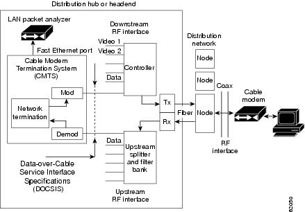
In addition, the cable monitor command can forward full DOCSIS packets, or it can strip the DOCSIS headers and forward only the Ethernet frames. Packets can also be timestamped to aid in troubleshooting. The packets are then forwarded out of the specified Ethernet or Fast Ethernet port to the LAN analyzer for additional analysis.
Figure 4-1 illustrates a LAN packet analyzer attached to a Fast Ethernet port in a DOCSIS two-way configuration.
Figure 4-1 LAN Packet Analyzer in a DOCSIS Two-Way Configuration
Note
Tip
%LINK-4-TOOBIG:Interface Ethernet2/0, Output packet size of 1518 bytes too big
This error message is typically accompanied by a traceback display. Both the error message and traceback are informational only and can be ignored. They do not indicate a traffic flow problem with the cable modem being monitored.
Overview of CISCO-TAP-MIB
There is no user-accessible CLI to support the SII feature. All interaction is implemented by means of SNMPv3, and all configurations, both for taps (SII intercepts) as well as the mediation device, are implemented by means of the CISCO-TAP-MIB.
Note
Table 4-1 lists the objects in the MIB, as well as restrictions for the Cisco uBR10012 CMTS other than those listed in the MIB itself.
Table 4-1 CISCO-TAP-MIB Objects and Restrictions
cTapMediationDestAddressType
Only IPv4 is supported (ITD restriction)
cTapMediationDestAddress
cTapMediationDestPort
cTapMediationSrcInterface
cTapMediationRtcpPort
Not supported (ITD restriction1 )
cTapMediationDscp
cTapMediationDataType
cTapMediationRetransmitType
Not supported (ITD restriction)
cTapMediationTimeout
cTapMediationTransport
UDP only (ITD restriction)
cTapMediationNotificationEnable
cTapMediationStatus
cTapMediationCapabilities
cTapStreamCapabilities
cTapStreamIpInterface
Only if interface is cable
cTapStreamIpAddrType
IPv4 only
cTapStreamIpDestinationAddress
cTapStreamIpDestinationLength
Must be 32 (no subnets)
cTapStreamIpSourceAddress
cTapStreamIpSourceLength
cTapStreamIpTosByte
cTapStreamIpTosByteMask
cTapStreamIpFlowId
Not supported (IPv6 only)
cTapStreamIpProtocol
cTapStreamIpDestL4PortMin
Must match ...DestL4PortMax, or zero
cTapStreamIpDestL4PortMax
Must match ...DestL4PortMin, or 65535
cTapStreamIpSourceL4PortMin
Must match ...SourceL4PortMin, or zero
cTapStreamIpSourceL4PortMax
Must match ...SourceL4PortMax, or 65535
cTapStreamIpInterceptEnable
cTapStreamIpInterceptedPackets
cTapStreamIpInterceptDrops
cTapStreamIpStatus
1 This means the restriction is across all Cisco platforms, not just Cisco CMTS platforms.
Benefits
The cable intercept command helps the CMTS or network administrator to:
•
•
Monitoring upstream and downstream data packets with the cable monitor command helps the CMTS or network administrator to:
•
•
SII, with SNMPv3, helps the CMTS or network administrator, in conjunction with law enforcement, to:
•
•
How to Configure Cable Intercept and Monitoring Features
See the following sections to enable and configure the cable intercept and monitoring features.
•
•
Configuring the Cable Intercept Feature
To enable the cable intercept feature on a particular cable interface, use the following procedure, starting in privileged EXEC mode.
SUMMARY STEPS
1.
2.
3.
4.
5.
6.
DETAILED STEPS
Configuring the Cable Monitor Feature
To enable cable monitoring on a particular cable interface, use the following procedure, starting in privileged EXEC mode.
Note
SUMMARY STEPS
1.
2.
3.
4.
interface interface {access-list {name | number} | mac-address address | sid sid-number}
[packet-type {data docsis | data ethernet | [mac type type] } ]5.
6.
DETAILED STEPS
Step 1
enable
Example:Router> enable
Router#
Enables privileged EXEC mode. Enter your password if prompted.
Step 2
configure terminal
Example:Router# configure terminal
Router(config)#
Enters global configuration mode.
Step 3
interface cable x/y
Example:Router(config)# interface cable 4/0
Router(config-if)#
Enters cable interface configuration mode for the specified cable interface.
Step 4
cable monitor [incoming | outbound] [timestamp] interface interface {access-list {name | number} | mac-address address | sid sid-number} [packet-type {data docsis | data ethernet | mac [type type]}]
Example:Router(config-if)# cable monitor interface e1/2 mac-address 0123.4567.89ab packet-type data docsis
Router(config-if)#
Enables cable monitoring on the cable interface with the following parameters:
•
•
•
•
Identify the packets to be monitored with one of the following:
•
•
•
You can configure the types of packets to be forwarded with the following options:
•
–
–
–
Note
Step 5
exit
Example:Router(config-if)# exit
Router(config)#
Exits interface configuration mode.
Step 6
exit
Example:Router(config)# exit
Router#
Exits global configuration mode.
Monitoring the Cable Intercept and Monitor Features
To display information about the operation of the cable intercept and cable monitor commands, use the following procedures:
•
•
Displaying Information About Intercepted Traffic
To display information about what traffic is being forwarded by the cable intercept command, use the show interface cable intercept command:
Router# show interface c6/0 interceptDestination DestinationMAC Address IP Address UDP Port00C0.0102.0DEF 10.10.10.131 7512Router#Displaying Information About Monitored Traffic
To display information about what traffic is being sent to the external LAN analyzer by the cable monitor command, use the show interface cable monitor command:
Router# show interface cable 1/0 monitorUS/ Time Outbound Flow Flow Type Flow Packet MAC MAC EncapDS Stmp Interface Type Identifier Extn. Type Extn. Type Typeall yes Et1/0 mac-addr 0050.5462.008c yes data no - Ethernetus yes Et1/0 acc-list 300 no - no - -us no Et1/0 sid 2 yes mac yes map-grant -all no Et1/0 acc-list rrr no - no - -all no Et1/0 mac-addr 0042.b013.008c yes data no - Ethernetall no Et1/0 upstream 0 yes data no - docsisRouter#Configuration Examples
The following examples illustrate sample configurations of the cable intercept and cable monitor commands and features on the Cisco CMTS:
Cable Intercept Examples
Cable Intercept Configuration Example
The following sample configuration shows traffic to and from MAC address 0003.e3fa.5e11 being forwarded to a data collection server at the IP address 172.18.73.189 and UDP port 9999:
!interface Cable3/0cable intercept 0003.e3fa.5e11 172.18.73.189 9999...Cable Monitor Examples
This section contains the following examples that illustrate the Cable Monitor feature on the Cisco CMTS:
•
•
•
•
Cable Monitor Configuration Example (MAC Address)
The following example of the cable monitor command on a Cisco uBR7114 router monitors packets with the MAC address of 0002.b9ff.8c00. Both upstream and downstream packets are forwarded to a LAN analyzer on the router's Fast Ethernet interface (FE0/0).
!interface cable 1/0cable monitor timestamp int fe0/0 mac-address 0002.b9ff.8c00 packet-type data ethernet...Cable Monitor Configuration Example (Ethernet, MAC-Layer, and DOCSIS-Data Packets)
The following example of the cable monitor command monitors Ethernet, MAC-layer, and DOCSIS-data packets with the MAC address of 0003.e3fa.5e8f, adding a timestamp to the packets before forwarding them to the LAN analyzer.
!interface Cable 3/0ip address 10.100.100.1 255.255.255.0cable monitor timestamp int e2/0 mac-address 0003.e3fa.5e8f packet-type data ethernetcable monitor timestamp int e2/0 mac-address 0003.e3fa.5e8f packet-type maccable monitor timestamp int e2/0 mac-address 0003.e3fa.5e8f packet-type data docsis...Cable Monitor DOCSIS Data Packets Example
This example shows sample DOCSIS packets that have been captured by the cable monitor command and forwarded to a LAN analyzer. The hexadecimal dump for the first packet is the following:
LLC: ----- LLC Header -----LLC:LLC: DSAP Address = E2, DSAP IG Bit = 01 (Group Address)LLC: SSAP Address = FA, SSAP CR Bit = 00 (Command)LLC: I frame, N(R) = 71, N(S) = 47, POLLLLC:DLC: Frame padding= 43 bytesADDR HEX ASCII0000:c0 00 00 1c ea 1d 00 03 fe e1 a0 54 00 03 e3 fa | ...........T....0010:5e 8f 00 0a 00 00 03 01 04 00 00 03 00 00 00 8a | ^...............0020:4d 6e 00 00 00 00 00 00 00 00 00 00 00 00 00 00 | Mn..............0030:00 00 00 00 00 00 00 00 00 00 00 00 | ............The relevant DOCSIS bytes are the following:
•
•
•
The hexadecimal dump of the next packet is the following:
LLC: ----- LLC Header -----LLC:LLC: DSAP Address = FE, DSAP IG Bit = 00 (Individual Address)LLC: SSAP Address = E0, SSAP CR Bit = 01 (Response)LLC: I frame, N(R) = 42, N(S) = 80LLC:DLC: Frame padding= 43 bytesADDR HEX ASCII0000:c2 00 00 2b 00 00 00 03 e3 fa 5e 8f 00 03 fe e1 | ...+......^.....0010:a0 54 00 19 00 00 03 01 05 00 00 03 01 01 04 00 | .T..............0020:00 00 00 02 01 00 03 02 00 00 05 01 03 00 8a 4d | ...............M0030:6e 00 00 00 00 00 00 00 00 00 00 00 | n...........This packet has a MAC message type of 05, indicating a Ranging Response (RNG-RSP) message.
Note
Cable Monitor Timestamped Packets Example
The following example shows how to interpret the four-byte timestamp that is appended to packets that are forwarded by the cable monitor command when using the timestamp option. The following hexadecimal dump shows the 64-byte contents of the first MAP message packet being examined:
0000(0000): C302003A 00000000 01E02F00 00010008...:....../.....0010(0016): 0D6F4670 00260000 03010300 01380400 .oFp.&.......8..0020(0032): 0061A1C1 0061A07C 00030004 FFFC4000 .a...a.|......@.0030(0048): 0189401F FFFC4042 0001C043 007EF4EA ..@...@B...C.~..The relevant portions of this packet are the following:
•
•
•
The following hexadecimal dump shows the second MAP message being forwarded:
0000(0000): C302003A 00000000 01E02F00 00010008 ...:....../.....0010(0016): 0D6F4670 00260000 03010300 01380400 .oFp.&.......8..0020(0032): 0061A5AE 0061A469 00030004 FFFC4000 .a...a.i......@.0030(0048): 0189401A FFFC403D 0001C03E 007EF4EF ..@...@=...>.~..In this example, the timestamp is 0x007EF4EF. Subtracting the two timestamps (0x007EF4EF-0x007EF4EA) produces the time difference between the two MAP messages in hundredths of a second (which in this case is a difference of 5, for a total time difference of 50 milliseconds).
Additional References
For additional information related to the Cable Monitor and Intercept feature, refer to the following references:
Related Documents
CMTS Command Reference
Cisco IOS CMTS Cable Command Reference, at the following URL:
http://www.cisco.com/en/US/docs/ios/cable/command/reference/cbl_book.htmlCisco IOS Release 12.2 configuration guide
Cisco IOS Release 12.2 Configuration Guides References, at the following URL:
http://www.cisco.com/en/US/products/sw/iosswrel/ps1835/products_installation_and_configuration_guides_list.htmlCisco IOS Release 12.2 command reference
Cisco IOS Release 12.2 Command References, at the following URL:
http://www.cisco.com/en/US/products/sw/iosswrel/ps1835/prod_command_reference_list.htmlCommon Open Policy Service (COPS)
COPS Engine Operation on the Cisco CMTS
PacketCable Configuration
PacketCable for the Cisco CMTS, in the Cisco CMTS Feature Guide, at the following URL:
http://www.cisco.com/en/US/docs/ios/cable/configuration/guide/cmts_pktcable_mm_ps2209_TSD_Products_Configuration_Guide_Chapter.htmlUsing the LAN analyzer
See the documentation for the LAN analyzer or other network interception software you are using for instructions on decoding DOCSIS MAC frames.
Note
CALEA Information
See the Communications Assistance for Law Enforcement Act (CALEA), which was passed by the United States Congress in 1994 and is now sections 1001 to 1010 of the United States Code Title 47 (Telegraphs, Telephones, and Radiotelegraphs).
Also see the information on Cisco's web site at the following URL:
http://www.cisco.com/wwl/regaffairs/lawful_intercept/index.htmlLawful Intercept
Lawful Intercept Technical Documentation at the following URL:
http://www.cisco.com/en/US/tech/tk583/tk799/tsd_technology_support_protocol_home.html
Standard s
Data-Over-Cable Service Interface Specifications Radio Frequency Interface Specification, version 1.1 (http://www.cablelabs.com/cablemodem)
PacketCable™ Electronic Surveillance Specification (http://www.cablelabs.com/packetcable)
1 Not all standards supported by this release are listed.
MIBs
CISCO-TAP-MIB
To locate and download MIBs for selected platforms, Cisco IOS releases, and feature sets, use Cisco MIB Locator found at the following URL:
1 Not all MIBs supported by this release are listed.
RFCs
Technical Assistance