Version 1.0

Introduction
Cisco Network Admission Control and Microsoft Network Access Protection Integration Overview
• For additional information about the Cisco NAC solution, see http://www.cisco.com/go/nac.
• For additional information about the Microsoft NAP solution, see http://www.microsoft.com/nap.
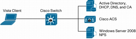
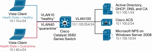
Topology
Figure 1. Basic Topology for NAC-NAP Interoperability Architecture
Configuration Scenarios
IEEE 802.1x Method
Figure 2. IEEE 802.1x Method Setup
NAC-NAP Network Hardware Requirements
Supported Cisco Catalyst Switch Platforms
Table 1. Switch Platforms Supported by NAC-NAP
NAC-NAP Client Requirements
Table 2. Client Requirements
Note: Cisco Trust Agent is not required for clients with the Microsoft Vista OS.
NAC-NAP Server Requirements
Table 3. Server Requirements
Admission Control Predeployment Checklist
Security Policy Creation and Maintenance
• What are your current security policies for each of these domains?
• Who (and what) is responsible for policy creation? Policy enforcement?
• What is the quorum for making changes?
• Will network access authorizations be based on identity or posture, or both?
• What is your policy on unmanaged and nonstandard machines on your network (labs, guests, consultants, extranets, kiosks, etc.)?
• How will you handle acquisitions that may have a different network infrastructure and policy?
Public Key Infrastructure
• Have you already deployed an enterprise public key infrastructure (PKI)? Windows 2000 Server or later, a CA vendor, or other?
• If not, will you install and manage one or purchase individual certificates from a CA vendor?
• Do you understand the long-term support, migration, and scaling requirements of self-signed certificates?
Directory Services
• Do you or will you require identity for network authorization?
• Have you already deployed directory services: Microsoft Active Directory, LDAP, or other?
• Will your existing installation scale to support the added queries or are more servers needed?
Network Access Devices
• A NAD acts as a policy-enforcement point for the authorized network access privileges that are granted to a host. Does your existing hardware support the desired NAC functions? Do you need to upgrade?
• Is a new Cisco IOS Software or Cisco Catalyst OS license required for the security (crypto) images?
• Do these NADs have enough memory for the larger Cisco IOS Software security images? Do you need a memory upgrade?
• Can these NADs run the NAC-supported versions of Cisco IOS Software and Cisco Catalyst OS or is another NAD required?
Hosts and Other Network-Attached Devices
• Do you already use IEEE 802.1x supplicants from Microsoft, Cisco, or some other vendor on a platform other than Windows Vista?
• Will an IEEE 802.1x upgrade require a supplicant purchase, OS upgrade, or hardware upgrade (printers, etc)?
• Do you need wired or wireless IEEE 802.1x supplicant functions? (The Cisco free supplicant is wired only.)
• Which authentication types are required? (The NAC-NAP Version 1 solution supports only EAP-FAST with EAP-Transport Layer Security [EAP-TLS], EAP-Generic Token Card [EAP-GTC], and EAP-Microsoft Challenge-Handshake Authentication Protocol Version 2 [EAP-MSCHAPv2] inner authorization methods.)
Nonresponsive Hosts
• Do you have nonresponsive hosts (NRHs)? Generally, an NRH is a host that does not have an IEEE 802.1x supplicant or NAP agent running to perform posture validation.
• Have you identified all of the NRH device types in your network:
– No IEEE 802.1x supplicant (unsupported or hardened OS)
– NAP agent disabled or not supported (unsupported OS or network boots)
– Otherwise unmanaged or uncontrolled devices (guests, labs, etc.)
• What is your authorization strategy for NRHs?
• Do you need to upgrade to IEEE 802.1x capabilities in your hardware or OS?
• Will you use whitelisting in Cisco Secure ACS (MAC authentication bypass [MAP] and MAC or IP wildcards)?
• Do you know the administrative and management costs of a MAP, host registration, and guest system?
Cisco Secure ACS
• Do you already use Cisco Secure ACS? Will you need to upgrade or purchase it?
• How many Cisco Secure ACSs will you need to scale the deployment based on your organization size, availability requirements, revalidation frequency, and policy size?
• How will you replicate the Cisco Secure ACS database and configuration changes: manually, periodically, scheduled, or instantly?
• Will any load-balancing hardware or software be necessary to handle a high volume of concurrent authorizations?
Third-Party Software Integration
• What existing desktop security software do you want to integrate with NAC-NAP?
• What new client software do you want to deploy because of NAC-NAP?
• Do you have the required version for NAC integration? Or is an upgrade, new purchase, or replacement required?
Patch Management
• What update, patch, or remediation software do you currently use, if any?
• Does this update software integrate with NAC-NAP?
• Will you have a remediation website for communicating the posture status to unhealthy or nonresponsive hosts?
• Will you distribute software to employees and guests from this site? How will you handle licensing?
Monitoring, Reporting, and Troubleshooting
• What is your existing monitoring and reporting framework?
• Will NAC logs and events integrate? Or is something additional needed?
• Do you have sufficient long-term storage space for all of these new logs and events?
Communications
• Have you communicated the solution to the organization for the various stages: awareness (need and benefits), readiness (what and when), and adoption (monitoring and enforcement)?
• How will you communicate: email, internal news, remediation website, support desk, etc.?
Support Desk
• Have you set up staff training for the new technology and processes?
• How will the support staff troubleshoot support calls related to NAC-NAP?
• What application development is required to resolve NAC-related issues?
• Have you reviewed the troubleshooting steps (list of required logs for opening cases, etc.)?
Configuration for NAC-NAP Integration
• Cisco Secure ACS 4.2 for Windows (Microsoft Windows Server 2008, Windows Server 2003, or Windows 2000 Server)
• Microsoft Windows Server 2008 (HCAP server including Microsoft NPS and IIS)
• Microsoft Windows Vista (Service Pack 1 is required)
• NAC-compatible Cisco Catalyst switch (such as the Cisco Catalyst 3750 Series Switch)
Cisco Secure ACS Base Configuration
Network Configuration
Task 1: Configure AAA Clients
Step 1. On the Network Configuration screen, click the hyperlink under Network Device Group. Click (Not Assigned) and move to the (Not Assigned) AAA Client screen.
Step 2. Configure the AAA clients by clicking the Add Entry button. You can define all NADs as a single AAA client using IP address wildcards. Shared Secret is an identical key string that you define for a switch RADIUS configuration. For Authenticate Using, be sure to select RADIUS (Cisco IOS/PIX 6.0). The following screenshot shows a sample configuration.
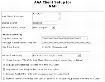
Step 3. Click Submit + Apply to save the changes.
Note: AAA client definitions with wildcards cannot overlap with other AAA client definitions, regardless of the authentication types. When adding more AAA clients with a different authentication type, avoid using wildcards and specify the AAA client IP address as needed.
Task 2: Configure AAA Servers
Note: Your AAA server is automatically populated during the installation of Cisco Secure ACS, using the hostname assigned to the host operating system.
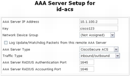
Step 1. Configure the Key setting for the AAA server as shown in the following screenshot. Choose Network Configuration > Network Device Group > (Not Assigned) and click the AAA server name hyperlink id-acs. This shared secret key is used by the remote AAA server and Cisco Secure ACS to encrypt the data. The key must be configured identically in the remote AAA server and the local Cisco Secure ACS, including case sensitivity.
Note: You can optionally assign the Cisco Secure ACS to a previously configured network device group (NDG). When adding a Cisco Secure ACS to a network device group, make sure that shared secret for NDG matches the Cisco Secure ACS's shared secret.
Interface Configuration
Task 1: Configure RADIUS Attributes
Step 1. Choose Interface Configuration from the main menu, choose RADIUS (IETF), and select the attributes shown in the screenshot. Then choose RADIUS Cisco IOS/PIX6.0 and select the attribute shown in the screenshot. Only the attributes checked are necessary for NAC. All other attributes should by unchecked to save time in later configuration steps.
|
Options |
|
|
RADIUS (IETF) |
|
|
|
|
|
|
|
|
|
|
|
|
|
|
RADIUS (Cisco IOS/PIX6.0) |
|
Note: Attributes 64, 65, and 81 are necessary only for VLAN assignments. Attributes 27 and 29 are used for IEEE 802.1X reauthentication.
Step 2. Choose Interface Configuration > Advanced Options and enable the attributes shown here.
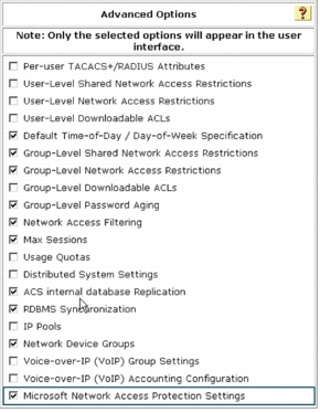
Note: Microsoft Network Access Protection Settings needs to be checked in this section to enable the HCAPv2 interface so you can configure the Microsoft NPS address.
System Configuration
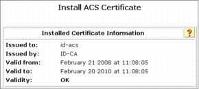
Task 1: Set Up Cisco Secure ACS Certificate and Root CA Certificate
Note: Using a production PKI and certificates signed by a production CA or registration authority is highly recommended for the most scalable NAC deployments. This part of NAC implementation has been significantly compressed and abbreviated; you will need to use an existing PKI (internal or outsourced) to securely identify the Cisco Secure ACS infrastructure to endpoint devices.
Step 1. Choose System Configuration > ACS Certificate Setup > Generate Certificate Signing Request. Fill out the required field as shown here and click the Submit button.
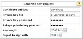
Examples of field values for the certificate signing request (CSR) are shown here.
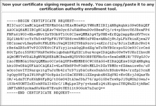
After you submit your request, your CSR is displayed in the right frame of your browser console.
Step 2. Now send the CSR to the Microsoft CA server. Copy your CSR to a temporary text file. Then access your CA server using Microsoft Internet Explorer (IE). The local Microsoft CA server can be accessed through the following URL: http://your_ca_server/certsrv/
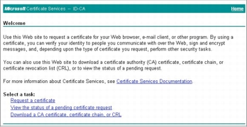
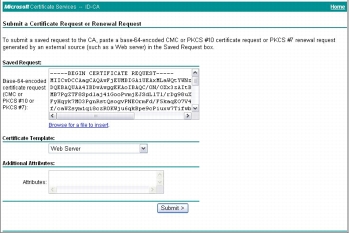
Step 3. Click Request a certificate > advanced certificate request > Submit a certificate request by using a base-64-3ncoded CMS or PKCS #10, or submit a renewal request by using a base-64-encoded PKCS #7 file.
Step 4. Paste your copied CSR from the Cisco Secure ACS web console to the Saved Request text box. For Certificate Template, choose Web Server; then click Submit.
Step 5. Select DER encoded to download your Distinguished Encoding Rules (DER) encoded certificate to your certificate directory on Cisco Secure ACS (or you may need to download the certificate to your Cisco Secure ACS Solution Engine server). Name the downloaded certificate to distinguish it from the root CA server of this Microsoft CA server. Alternatively, you may want to save the CA certificate in both DER and Base 64 encoding methods and then save them both with appropriate names.
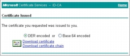
Step 6. (Optional) When you are accessing the CA web enrollment console, we recommend that you download the CA server root certificate and save it along with the Cisco Secure ACS certificate for future use. To download the CA root certificate, access your CA server with IE and click Download a CA certificate, certificate chain, or CRL under Select a task section of Welcome page.
Step 7. Make sure you choose the current CA server and then click Download certificate.
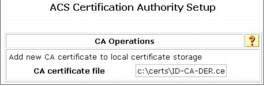
Step 8. Now you have a root CA certificate, Cisco Secure ACS certificate, and associated private key saved on your Cisco Secure ACS. You have to install those certificates and the private key on Cisco Secure ACS. First install the root CA certificate on Cisco Secure ACS. Choose System Configuration > ACS Certificate Setup > ACS Certification Authority Setup. Specify the location of the CA certificate and click the Submit button.
Step 9. After you add the new CA certificate, restart Cisco Secure ACS. Choose System Configuration > Service Control and click Restart.
Step 10. After installing the CA certificate, you should add it to the certificate trust list (CTL) as a trusted authority. To do this, select the Edit Certificate Trust List link from the ACS Certificate Setup screen, locate the name of your CA in the list, and check the box next to it and click Submit to save the changes.
Step 11. Changing the CTL requires a Cisco Secure ACS restart; choose System Configuration > Service Control and click the Restart button.
Step 12. Choose Install Certificate. Specify the location of the Cisco Secure ACS certificate and click the Submit button.
|
Install New Certificate |
|
|
Read certificate from file |
|
|
Certificate file: |
c:\certs\id-acs.cer |
|
Private key file: |
c:\certs\id-acs.pvk |
|
Private key password: |
cisco123 |
Step 13. After a successful installation of the Cisco Secure ACS certificate, you must restart Cisco Secure ACS. Choose System Configuration from the main menu, select Service Control, and click the Restart button. This completes the Cisco Secure ACS certificate installation process.
Step 14. (Optional) Choose System Configuration > ACS Certificate Setup > Generate Certificate Signing Request. Fill out the required fields as shown here and click the Submit button.
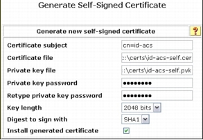
Note: Self-signed server certificates generated on Cisco Secure ACS should be used for lab testing purposes only. This certificate is valid for one year only, and the administrator is advised to not deploy a self-signed certificate for any production use.
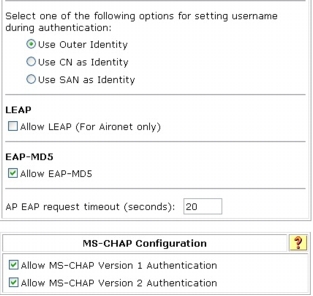
Task 2: Set Up Global Authentication
Note: Unless you have a limited deployment environment or specific security concerns, we highly recommend that you enable all protocols globally. You will have an opportunity to limit the actual protocol options later when you create the network access profiles for NAC, but if they are not enabled here, they will not be available in the network access profiles.
Step 1. Choose System Configuration > Global Authentication Setup.
Step 2. Select the global authentication parameters shown here to make them available for the network access profile authentication configuration. Note that Protected EAP (PEAP) and its inner authentication methods are also selected. PEAP is not required for NAC-NAP integration. Those methods can be disabled in the network access profile.
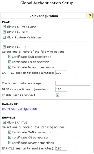
Step 3. Click Submit + Restart to save these changes.
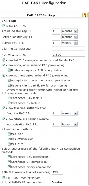
Step 4. Choose EAP-FAST Configuration to open the EAP-FAST Configuration page. Select the parameters shown here
Step 5. Click Submit + Restart to save these changes.
Task 3: Configure Attributes for Logging
Note: To log any attribute values from hosts other than NAC attribute values, you must first import the attribute definitions into Cisco Secure ACS and then select them for logging.
Step 1. To specify which log files are enabled and which event attributes are recorded within them, choose System Configuration > Logging.
The recommended log files and their logged attributes for NAC are shown here. Make sure logging for CSV Failed Attempts, CSV Passed Authentications, and CSV RADIUS Accounting are all turned on.
Administration Control Configuration
Task 1: Add Remote Administrator Access
Step 1. Choose Add Administrator and in the Administration Control section add the information shown here.
|
Add Administrator |
|
|
Administrator Name: |
administrator |
|
Password: |
cisco123 |
|
Administrator Privilege: |
Grant All |
Shared Profile Components Configuration
Note: Network access profiles are introduced in Cisco Secure ACS 4.0. They enable you to create and map individual authentication, posture validation, and authorization components depending on the access method being used.
Task 1: Configure RADIUS Authorization Components
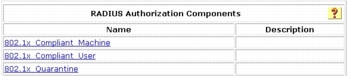
Step 1. To configure RACs, choose Shared Profile Components > RADIUS Authorization Components and click the Add button for each new RAC you want to create. Each RAC can contain one or more vendor RADIUS attributes, including Cisco IOS/PIX 6.0 and IETF.
Note: The session timeout value used for NAC deployments can significantly affect Cisco Secure ACS performance. We strongly recommended that you adjust the timeout value for the scale of your network and the Cisco Secure ACS transaction capacity.
Step 2. Specify RAC entries, attribute assignments, and values. Create these RAC configurations for a IEEE 802.1x scenario (NAC Layer 2 IEEE 802.1x).
Step 3. For the IEEE 802.1x scenario, you should have three RACs total. Now the Cisco Secure ACS service needs to compile those RACs. Choose System Configuration > Service Control > Restart to compile the RACs.
Group Setup Configuration
Task 1: Set Up User Groups
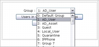
Step 1. By default, Cisco Secure ACS already has 500 user groups. You will start by renaming four of these groups. Choose Group Setup from the main Cisco Secure ACS menu. From the Group pull-down menu, choose 1: Group 1 and click Rename Group. Type AD_User and click Submit. Repeat those steps for each of the other groups using the group names shown here.
|
Group Number |
Group Name |
|
1: Group 1 |
AD_User |
|
2: Group 2 |
AD_Asset |
|
4: Group 4 |
Local_User |
|
5: Group 5 |
Quarantine |
Task 2: Set Up Users
Step 1. Choose User Setup, for User, enter Vista, and click the Add/Edit button. Under User Setup for User: vista (New User), enter cisco123 as the user's password.
Step 2. In the Group to which the user is assigned drop-down menu, assign the user to the Local_User group. Scroll to the bottom and click the Submit button.
Note: The individual RADIUS attributes will be configured and applied in the Network Access Profile section and do not need to be configured for each individual group.
External User Database Configuration
Task 1: Configure Unknown-User Policy
Step 1. Choose External User Database > Unknown User Policy.
Step 2. Click Check the following external user database.
Step 3. Use the arrow button to move Windows Database from the External Databases box to the Selected Database and then click Submit.
Task 2: Map Database Groups
Step 1. Choose External User Database > Database Group Mappings.
Step 2. Under Unknown User Group Mappings, click Windows Database.
Step 3. Click New configuration to select your domain. In this task, use domain name ID, so in the Detected Domains list, select ID (or your domain) and click Submit.
Step 4. Click ID and start Cisco Secure ACS local group and NT group mappings. Click Add mapping and under NT Groups select Domain User and then click Add to selected. In the ACS group list, select AD_User and click Submit.
Step 5. Repeat these steps with the entries shown here to map the NT groups to Cisco Secure ACS local groups.
Note: Domain computer accounts are used to authenticate devices using IEEE 802.1x against Active Directory.
Task 3: Configure External User Database
Step 1. Choose External User Database > Database Configuration > Windows Database and click the Configure button to configure more detailed options for the Windows Active Directory database.
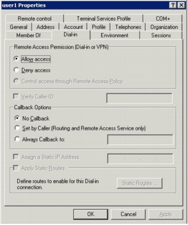
Step 2. Under Windows User Database Configuration, unselect Verify that "Grant dialin permission to user" setting has been enabled from within the Windows User Manager for users configured for Windows User Database authentication.
With this option disabled, Cisco Secure ACS will not check the Allow access remote access permission in the Active Directory user account properties. The following screenshot shows the user account properties on the Active Directory Users and Computers management console.
Note: This feature is disabled here for testing purpose only. You should revisit and evaluate this setting when deploying Cisco Secure ACS to a production network.
Step 3. Select Use the next sequential External Database in the Selected Databases list in case of an "External DB user invalid or bad password" error.
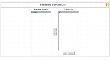
Step 4. Under Configure Domain List, use the arrow button to move your domain name, in this case, the domain name ID, from the Available Domains list to Domain List.
Note: If you are in a single domain, this operation is optional.
Step 5. Under MS-CHAP Settings, select both MS-CHAP version 1 and MS-CHAP version 2.
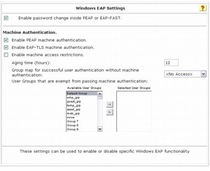
Step 6. Under Windows EAP Settings, select Enable password change inside PEAP or EAP-FAST.
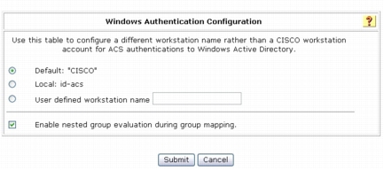
Step 7. Under Windows Authentication Configuration, select Default: "CISCO" as the workstation name and select Enable nested group evaluation during group mapping.
Posture Validation Configuration
Task 1: Set Up Cisco Secure ACS External Posture Validation
Step 1. Choose Posture Validation > External Posture Validation Setup.
Step 2. Under External Posture AAA Servers, click Add Server.
Note: Be sure to select External Posture AAA Servers, not External Posture Servers. External Posture Servers allows you to configure posture servers, which are HCAPv1 capable. External Posture AAA Servers provides an interface to the Microsoft NPS which is HCAPv2 compliant.
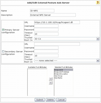
Step 3. In the Name field, add the hostname of the Microsoft NPS. In this example, the name for the Microsoft NPS is ID-NPS.
Step 4. Select Primary Server Configuration.
Step 5. Enter the URL (https://x.x.x.x/hcap/hcapext.dll) that will be used for communication between Cisco Secure ACS and the Microsoft NPS. In this example, the URL has been configured as the following: https://10.1.100.10/hcap/hcapext.dll
Step 6. Do not configure any username or password. The username and password are optional and should be used if these credentials are required by the IIS server.
Step 7. The default Timeout (Sec) value of 10 can be used. This value sets the interval between primary server failure and failover to the secondary server.
Step 8. To enable encrypted communication between Cisco Secure ACS and Microsoft NPS, an HTTPS connection can be established using a server certificate. Select the trusted root CA used for both Cisco Secure ACS and Microsoft NPS. In this example, the Trusted Root CA value is ID-CA. In the test environment, Secure Sockets Layer (SSL) communication can be turned off by changing the URL as described in Step 5 to http://x.x.x.x/hcap/hcapext.dll (the "s" is removed from https://).
Step 9. Select all the attributes in the Available Fwd Attributes box and use the arrow button to move them to the Selected Fwd Attributes box. The attributes include Endpoint-ID, Endpoint-IP-Address, Endpoint-Location, User-Group, and User-Name.
The following table shows the available attributes used in NAC-NAP IA and their definitions.
Completion of Common Cisco Secure ACS Configuration for IEEE 802.1x Scenario
Task 1: Complete the Configuration
Step 1. Choose System Configuration > Service Configuration. Under Services Log File Configuration, change the level of detail to Full. Click the Restart button to restart all Cisco Secure ACS services.
Windows Server 2008 Configuration
Note: In this document, Active Directory is running on Windows Server 2003. The CA service runs on the same server. Because some of the operations in this document require certificates for Windows Vista or Windows Server 2008 through web enrollment, we have applied the following hotfix on Windows Server 2003: http://support.microsoft.com/kb/922706
Task 1: Obtain a Computer Certificate for SSL
Note: To request an SSL certificate using the following procedure, the server must be joined to a domain with an available enterprise CA.
Step 1. Choose Start > Run, and in the Open field enter mmc. This operation opens a window called Console1.
Step 2. From the File menu, choose Add/Remove Snap-in.
Step 3. In the Add or Remove Snap-ins dialog box, click Certificates, click Add, select Computer account, click Next, and then click Finish. Then click OK to close the dialog box.
Step 4. In the left pane, double-click Certificate, right-click Personal, point to All Tasks, and then choose Request New Certificate.
Step 5. The Certificate Enrollment dialog box, opens. Click Next.
Step 6. Select the Computer check box as shown here and then click Enroll.
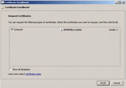
Step 7. Verify that Succeeded is displayed to indicate the status of certificate installation and then click Finish.
Step 8. Close the Console1 window.
Note: Your server may have more than one certificate in the local certificate store. Before choosing an SSL certificate, you can view the properties of these certificate by clicking a certificate in the list, then clicking Properties, and then clicking the Detail tab. A certificate used for SSL authentication must have a Subject field value that corresponds to the fully qualified domain name of the HCAP server (for example, ID-NPS.id.local), and an Enhanced Key Usage (EKU) field value of Server Authentication. The certificate must also be sent from a root CA that is trusted by the client computer. The computer certificate provisioned in this procedure meets these requirements.
Task 2: Run the Role Management Tool to Install the HCAP Server
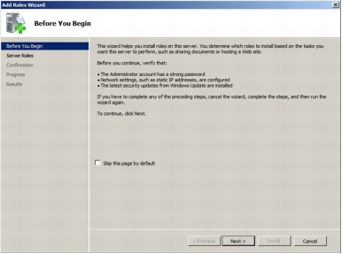
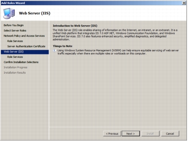
Step 1. To activate the RMT wizard, click Add Roles in the server manager user interface. The following screenshot shows the wizard's introductory page. Click Next to see the roles that can be installed on the server.
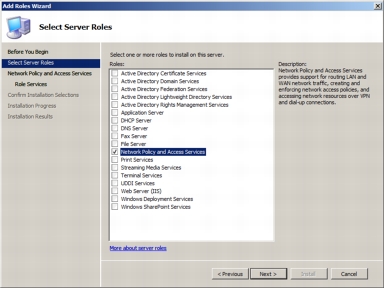
Step 2. The following screenshot shows the roles that can be selected on the server. Select the Network Policy and Access Services role and click Next.
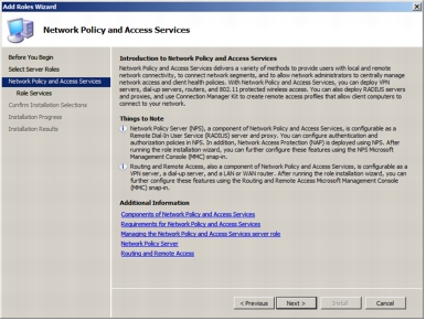
Step 3. The following screenshot shows the introductory page for the Network Policy and Access Services role. Click Next.
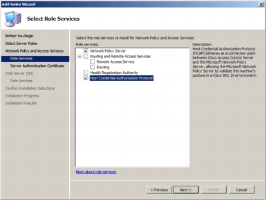
Step 4. Select Host Credential Authorization Protocol to install the HCAP server.
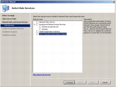
Step 5. Selecting Host Credential Authorization Protocol automatically selects Microsoft NPS.
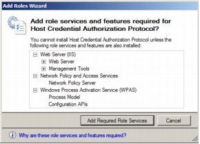
Step 6. Installation of HCAP requires dependent role services and features that will be installed automatically for the administrator. The following screenshot shows the dialog box listing all the dependent role services and features required for the HCAP server. Click Add Required Role Services.
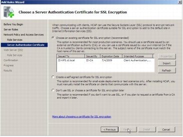
Step 7. The following screenshot shows the Server Authentication Certificate page, which allows the administrator to use an existing certificate. Select ID-NPS.id.local from the existing certificate list and click Next.
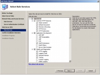
Step 8. Click Next on the Web Server (IIS) screen to get to the Select Role Services page.
Step 9. The following screenshot shows the role services that are being installed on the server. Click Next.
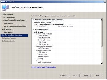
Step 10. The following screenshot shows the confirmation page before installation begins. Click Install to start the installation.
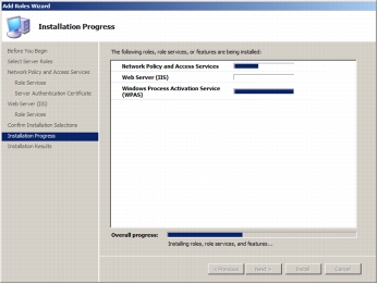
Step 11. The following screenshot shows the installation progress.
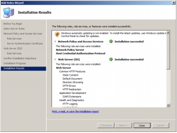
Step 12. The following screenshot shows that the installation has succeeded and that the HCAP server and its dependent components are installed.
Step 13. Open the Microsoft NPS Management Console, choose Start > Run, and in the Open field enter nps.msc. Then click OK. The following screenshot shows NPS Management Console.
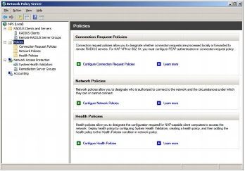
Network Policy Server Configuration
• Configure connection request policy (CRP)
• Configure system health validators (SHVs)
• Configure health policies
• Configure network policies
Task 1: Configure Connection Request Policy
Step 1. Double-click Connection Request Processing and then click Connection Request Policies.
Step 2. In the middle pane, under Name, right-click Use Windows authentication for all users and then click Delete. When a dialog box appears asking you to confirm the deletion, click OK. You will create a new connection request policy.
Step 3. Right-click Connection Request Policies, point to New, and then choose Custom.
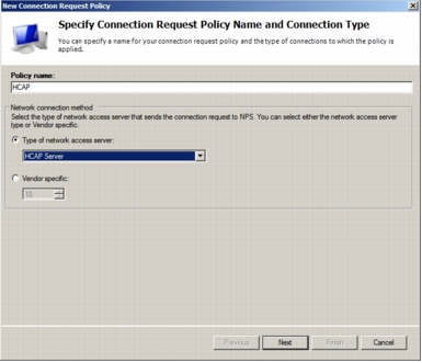
Step 4. In the New Connection Request Policy Properties box, on the Overview tab, for Policy name, type HACP. From the Type of network access server pull-down menu, choose HCAP Server. Your screen should look like the following screenshot. Click Next.
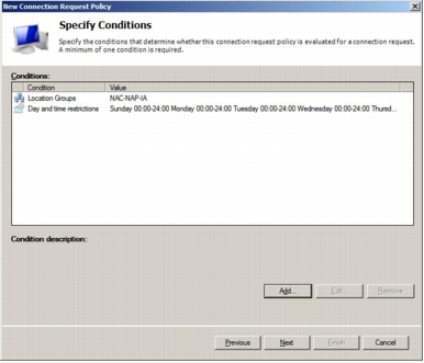
Step 5. In the New Connection Request Policy Properties box, click Add to add the conditions for the CRP to match.
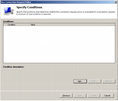
Step 6. In the Select Conditions dialog box that opens, you can select the conditions for the CRP. For this task, select the Day and Time Restriction condition to permit connections.
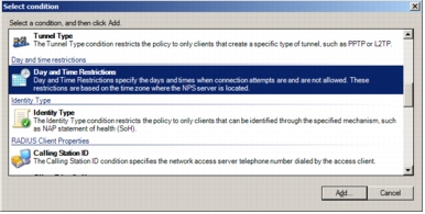
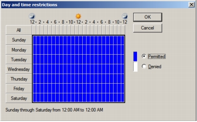
Step 7. The Day and time restrictions dialog box that opens permits all requests from the Cisco Secure ACS. Select a range as shown in the screenshot, click Permitted, and click OK.
Note: This is an example, and administrators can use whatever conditions apply to their specific deployments.
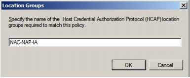
Step 8. Click the Add button again and this time choose HCAP Location Groups; then click Add.
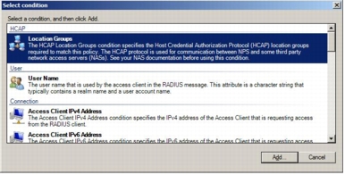
Step 9. In the Location Groups window, type the HCAP location group name: for example, NAC-NAP-IA. Microsoft NPS can use the HCAP location group name to identify HCAP requests by the specific Cisco Secure ACS. The same string is configured in the Posture section of the network access profile in the Cisco Secure ACS configuration.
Step 10. This task set up two conditions. Make sure you have the two entries for Conditions and then click Next.
Step 11. Select Authenticate requests on this server as shown here.
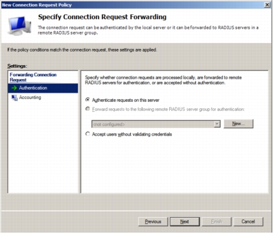
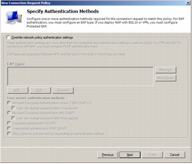
Step 12. Ensure that Override network policy authentication settings is not checked. The authentication settings should be set up in the network policies.
Step 13. On the Configure Settings page, click Next. Click Finish to complete the configuration of the CRP.
Task 2: Configure System Health Validators
Step 1. Double-click Network Access Protection and then click System Health Validators.
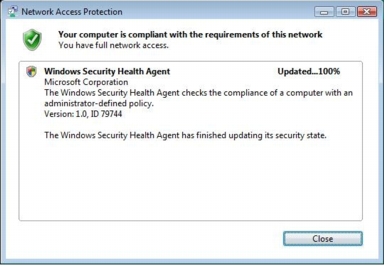
Step 2. In the middle pane, under Name, double-click Windows Security Health Validator.
Step 3. In the Windows Security Health Validator Properties dialog box, click Configure.
Step 4. Clear all check boxes except A firewall is enabled for all network connections, as shown in the following screenshot.
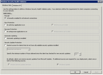
Step 5. Click OK to close the Windows Security Health Validator dialog box and then click OK to close the Windows Security Health Validator Properties dialog box.
Task 3: Configure Health Policies
Step 1. Double-click Network Access Protection.
Step 2. Right-click System Health Validator Templates and then click New.
Step 3. In the Create New SHV Template dialog box, under Name, type Compliant.
Step 4. Under Template type, verify that Client passes all SHV checks is selected.
Step 5. Under Select which SHVs must pass, select the Windows Security Health Validator check box, as shown in the following screenshot.
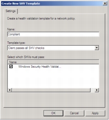
Step 6. Click OK.
Step 7. Right-click System Health Validator Templates and then click New.
Step 8. In the Create New SHV Template dialog box, under Name, type Noncompliant.
Step 9. Under Template Type, choose Client fails one or more SHV checks.
Step 10. Under Select desired SHVs, select the Windows Security Health Validator check box, as shown in the following screenshot.
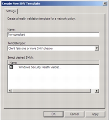
Step 11. Click OK.
Task 4: Configure Network Policies
Step 1. Click Network Policies.
Step 2. Delete the two default policies under Name by right-clicking the policies and then choosing Delete. Click OK to confirm each deletion.
Step 3. Right-click Network Policies, point to New, and choose New Network Policy.
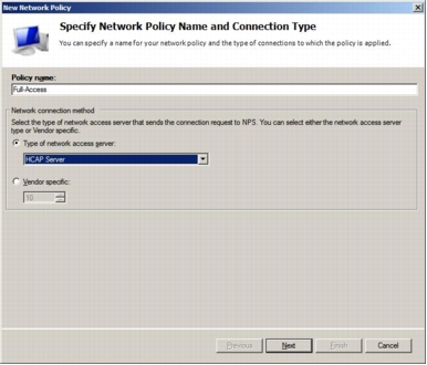
Step 4. In the New Network Policy window, under Policy name, name the new network policy; in this example, type Full-Access. Select Type of network access server and choose HCAP Server from the pull-down menu. Then click Next.
Step 5. In the Specify Condition window, click the Add button and choose Health Policies.
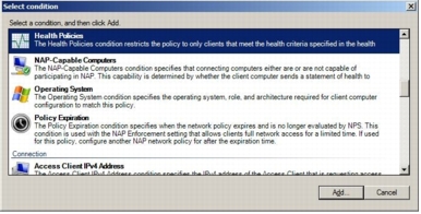
Step 6. From the Health Policies pull-down menu, choose Compliant, which was created in the previous task (Task 3). Click OK to go back to the Select Condition page and click Next.
Step 7. In the Specify Access Permission window, choose Access granted and click Next.
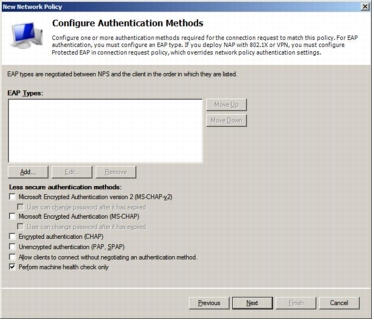
Step 8. In the Configure Authentication Methods window, deselect everything and select Perform machine health check only. Note that Microsoft NPS is used as the HCAP server, not the authentication server. Microsoft NPS is only performing a health check.
Step 9. In the Configure Constraints window, click Next and leave all options unchanged.
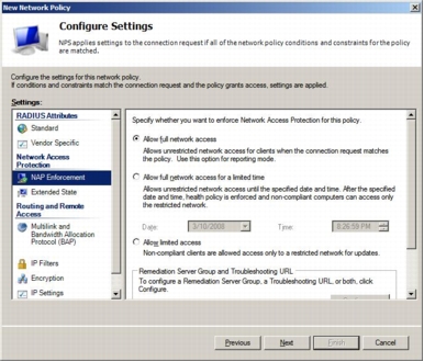
Step 10. In the Configure Settings window, first remove all predefined Standard RADIUS attributes (Framed-Protocol and Service-Type). Microsoft NPS communicates to Cisco Secure ACS using the HCAP protocol; therefore, no RADIUS attributes are involved. Then click NAP Enforcement in the settings list on the left side of the window. In NAP Enforcement settings pane that appears on the right, select Allow full network access and leave everything else deselected.
Step 11. Click Next and then click Finish to complete the Full-Access network policy.
Step 12. Repeat Steps 1 through 9 for a network policy named Restricted-Access. In the Specify Condition window, select Health Policies and then choose Noncompliant, which was created in the previous task (Task 3).
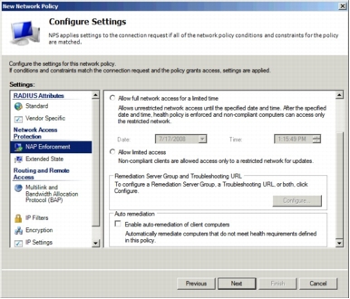
Step 13. In the Configure Settings window for a network policy named Restricted-Access, remove all predefined standard RADIUS attributes (Framed-Protocol and Service-Type). In the NAP Enforcement settings pane, select Allow limited access, and in the Auto remediation section, deselect Enable auto-remediation of client computers. Be sure to deselect the autoremediation in this section; otherwise, the NAP system changes the computer state (firewall state) immediately after IEEE 802.1x connection, and checking the switch port state (healthy or changed to quarantine VLAN ) is difficult.
Step 14. After configuring the Configure Settings window options, click Next and then click Finish to complete network policy configuration. This completes the Microsoft NPS setup.
Windows Vista Client Configuration
• Enable Network Access Protection Agent and Wired Autoconfiguration Service
• Enable EAP enforcement client and Windows Security Center
• Install and configure the Cisco EAP-FAST Module
Task 1: Enable Network Access Protection Agent and Wired AutoConfig Service
Step 1. Choose Start > All Programs > Accessories, right-click Command Prompt, and choose Run as Administrator.
Step 2. Type services.msc and press the Enter key. This operation opens a Services window.
Step 3. In the list of services, right-click Network Access Protection Agent and choose Properties.
Step 4. For Startup type, choose Automatic.
Step 5. Under Service status, click Start, wait for the service to start, and then click OK.
Step 6. In the list of services, right-click Wired AutoConfig and choose Properties.
Step 7. For Startup type, choose Automatic.
Step 8. Under Services status, click Start, wait for the service to start, and then click OK.
Step 9. Close the services window.
Task 2: Enable EAP Quarantine Enforcement Client and Windows Security Center
Step 1. Choose Start > All Programs, Accessories, right-click Command Prompt, and choose Run as Administrator.]
Step 2. Type mmc and press the Enter key. This operation opens a window called Console1.
Step 3. From the File menu, choose Add/Remove Snap-in.
Step 4. Select NAP Client Configuration and then click Add.
Step 5. In the NAP Client Configuration dialog box, click OK to accept the default selection Local computer (the computer on which this console is running).
Step 6. Select Group Policy Object Editor and then click Add.
Step 7. Click Finish to accept the default Group Policy Object selection Local Computer.
Step 8. In the Add or Remove Snap-ins dialog box, click OK.
Step 9. In the left pane of the Console1 window, double-click NAP Client Configuration (Local Computer) and then click Enforcement Clients.
Step 10. In the middle pane, right-click EAP Quarantine Enforcement Client and then click Enable.
Step 11. In the left pane, double-click Local Computer Policy, double-click Computer Configuration, double-click Administrative Templates, double-click Windows Components, and then click Security Center.
Step 12. In the middle pane, double-click Turn on Security Center (Domain PCs only).
Step 13. Select Enabled and then click OK.
Step 14. Close the Console1 window.
Step 15. Click No when prompted to save the console settings.
Note: Enable the NAP agent service on Vista. At the command prompt, enter the following command: net start napagent.
Note: Enable the NAP quarantine enforcement client (QEC) on Vista. At the command prompt, enter the following command: netsh nap cli set enforcement ID = 79623 ADMIN = "ENABLE".
Task 3: Install and Configure the Cisco EAP-FAST Module
Step 1. First, obtain EAP-FAST Module through Microsoft Windows Update. The EAP-FAST files will be installed in C:\program files\Cisco Systems\Cisco EAP-FAST Module.
Step 2. Choose Start > All Programs, Accessories, right-click Command Prompt, and choose Run as Administrator.
Step 3. Next to Open, type control netconnections and then click OK.
Step 4. Right-click Local Area Connection on the Network Connections screen and select properties.
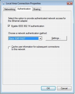
Step 5. Select the Authentication tab.
Note: This tab becomes available only when Wired AutoConfig service is started. If you do not see the Authentication tab, check the service status.
Step 6. Select the Enable IEEE 802.1x authentication check box.
Step 7. Under Choose a network authentication method, select Cisco EAP-FAST.
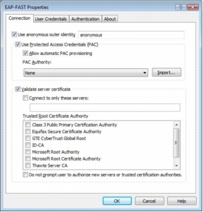
Step 8. On the Connection tab, select Use anonymous outer identity and use the default identity of anonymous.
Step 9. Select the Use Protected Access Credential option and select Allow automatic PAC provisioning. A protected access credential (PAC) authority will not be available at this point. You will first need to provision a PAC during the initial client authentication,
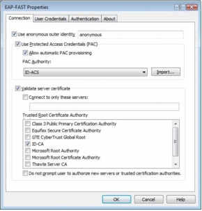
Step 10. Select Validate Server Certificate and select the appropriate CA from the Trusted Root CA drop-down list. If your trusted root CA is not in the list, select the Validate Server Certificate check box and deselect the Do not prompt user to authorize new servers or trusted certification authorities check box. The next time the user is authenticated successfully, the trusted root CA certificate will be provisioned, with a prompt to verify the provisioned certificate.
Step 11. On the User Credentials tab, the default setting Use Windows user name and password should be selected. If you are testing with a username and password that differs from the one used in the Windows logon, choose Prompt automatically for username and password.
Step 12. Select the Authentication tab. For Authentication method, select EAP-MSCHAPv2. Also select the Allow fast reconnect and Enable posture validation options.
Configuration of IEEE 802.1x on the Cisco IOS Software Switch
Task 1: Configure AAA on the NAD
Step 1. Enable AAA on the switch service using the aaa new-model global configuration command.
Step 2. Configure the switch to use RADIUS for IEEE 802.1x authentication using the aaa authentication dot1x default group radius command.
Step 3. Configure the switch to run authorization for all network-related service requests using the aaa authorization network default group radius command.
Step 4. Configure the switch to use RADIUS for IEEE 802.1x accounting using the aaa accounting dot1x default start-stop group radius command.
Step 5. Verify that the VLANs and VLAN interfaces listed here have been preconfigured on the switch for NAC L2 802.1x.
|
VLAN Name |
VLAN |
Subnets |
|
healthy |
10 |
10.1.10.x/24 |
|
guest |
20 |
10.1.20.x/24 |
|
quarantine |
40 |
10.1.40/x/24 |
|
asset |
50 |
10.1.50.x/24 |
|
voice |
99 |
10.1.99.x/24 |
Step 6. Enable IEEE 802.1x using the dot1x system-auth-control global configuration command.
Step 7. Enable IEEE 802.1x on Fast Ethernet 1/1.
Network Access Profile Configuration for NAC L2 802.1x
• Add an empty profile and configure all the necessary information.
• Use the template profiles to customize the network access profile desired with the base information included in the template.
• NAC L3 IP
• NAC L2 IP
• NAC L2 802.1x
• Microsoft IEEE 802.1x
• Wireless (NAC L2 802.1x)
• Agentless Host for L2 (802.1x fallback)
• Agentless Host for L3
• Agentless Host for L2 and L3
Task 1: Create the NAC L2 802.1x Profile from the Template
Step 1. Choose Network Access Profiles from the main menu and select Add Template Profile.
Step 2. Create a Network Access Profile for IEEE 802.1x by selecting the NAC L2 802.1x template from the Template drop-down menu. Select Active to enable the profile.
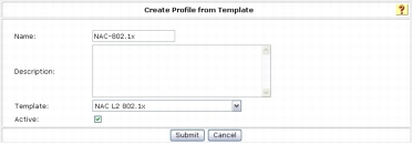
Step 3. Click Submit.
Task 2: Configure the Profile
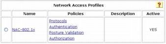
Step 1. On the Network Access Profiles screen, select the NAC-802.1x link for the new IEEE 802.1x profile.
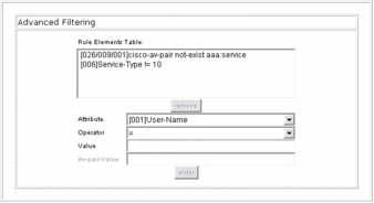
Step 2. Verify that the profile includes the following elements in Rule Elements Table under Advanced Filtering:
These elements should be automatically populated when the profile is created from the template.
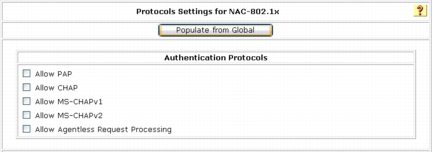
Step 3. On the Network Access Profiles screen, select the Protocols link for the new IEEE 802.1x profile.
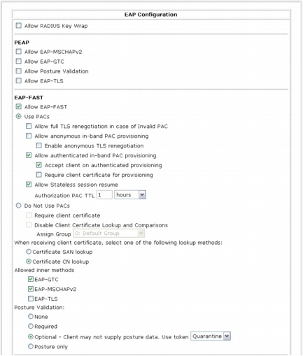
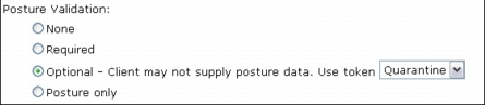
Step 4. Notice that a portion of the EAP-FAST configuration is already selected as part of the base template. Leave the default EAP-FAST configuration as is except under Posture Validation, select Optional and choose Quarantine as the token from the drop-down list.
Note: This setting is very important; if a Vista client requests access and can provide only a user or machine identity credential and cannot provide SoH information (for instance, the NAP agent is not running), then this setting can still give the user access to the quarantine VLAN, instead of rejecting network access entirely.
Step 5. Click Submit.
Step 6. Select the Authentication link from the Network Access Profile screen for the profile you created.
Step 7. Under Credential Validation Databases, use the arrow buttons to move Windows Database from Available Databases to Selected Databases. You are going to authenticate the user and machine using the IEEE 802.1x protocol against Microsoft Active Directory.
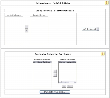
Step 8. Click Submit to apply change.
Step 9. On the Network Access Profile screen, select the Posture Validation link for the profile you created.
Step 10. Under Posture Validation Rule, click NAC-SAMPLE-POSTURE-RULE link and click Delete. This rule is automatically generated when a NAC-802.1x profile is created using the template, and you are not going to use this rule in this task.
Step 11. Click the Add Rule button for the Statement of Health Posture Validation Rule.
Step 12. In the Name field, type the name of the policy. In this example, the name is ID-NPS.
Step 13. In the Action section, enter a name for End Point Location. In this example, the name is NAC-NAP-IA. Remember that this value needs to be match the HCAP location ID that was configured in the Microsoft NPS connection request policies. Please refer to Network Policy Server Configuration, Task 1 Step 9 section to make sure the same Location Group string is used in the NPS configuration.
Step 14. Select External Posture Validation Server. In this example, the name is the name of our Microsoft NPS ID-NPS.
Step 15. Select the Reject User box. The Failure Posture Token should be dimmed.
Remember that the Reject User option for Failure Action can be turned off when the selected Microsoft NPS becomes available if Cisco Secure ACS can still send at least a posture token (in this case, a quarantine token) back to the NAD. For testing purposes, you will disable this feature and fail authentication when Microsoft NPS is not available.
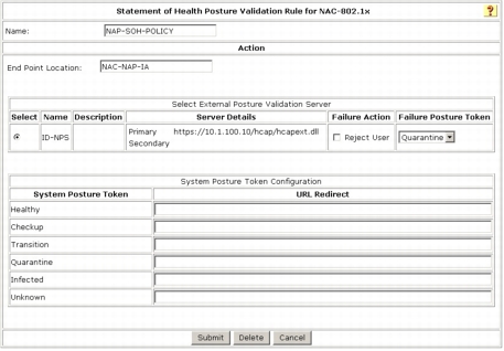
Step 16. For System Posture Token Configuration, type your remediation URL under URL Redirect. Upon quarantine, user HTTP traffic is redirected to this URL for further user notification purposes.
Step 17. Click the Submit button.
Note: We recommend the use of Failure Posture Token instead of Reject User in Failure Action. If the client responds with an empty SoH, meaning that no posture information is available on Vista, the system returns the configured token instead of rejecting the access request. It is highly likely that clients will not send SoH if the NAP agent is not configured properly or if dot3svc starts before NAP service.
Task 3: Configure Authorization section of the NAC-802.1x Profile
Step 1. Select the Authorization link for the NAC-802.1x profile.
Step 2. Enable authorization as shown in following screenshot. This configuration specifies the following conditions:
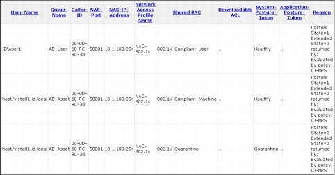
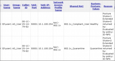
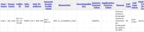
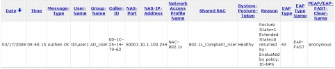
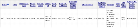
• If the user is successfully authenticated against Active Directory, and if the user's Active Directory group is mapped to Cisco Secure ACS local group AD_User, and if SoH evaluation by Microsoft NPS returns the Healthy token, then send authorization rule 802.1x_Compliant_User.
• If a device is successfully authenticated against Active Directory, and if the device's Active Directory group is mapped to Cisco Secure ACS local group AD_Machine, and if SoH evaluation by Microsoft NPS returns the Healthy token, then send authorization rule 802.1x_Compliant_Machine.
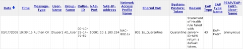
• If a user or device is authenticated successfully against Active Directory but SoH evaluation by Microsoft NPS returns the Quarantine token, then send authorization rule 802.1x_Quarantine.
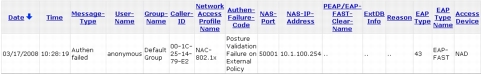
• If none of these conditions match, then reject authentication.
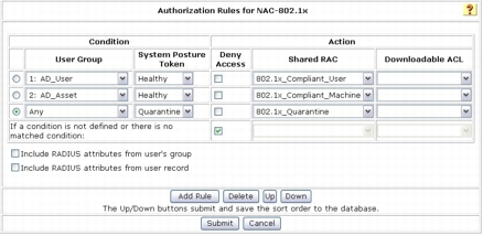
Step 3. Click Submit.
Task 6: Test Basic Client Authentication to Cisco Secure ACS
Step 1. On the Windows Vista client, choose Start > All Programs > Accessories, right-click Command Prompt, and choose Run as Administrator. In the Command Prompt console, type control netconnections to display the Network Connections window.
Step 2. In the Network Connections window, right-click Local Area Connection and select properties. If the user access control (UAC) asks permission to continue, click Continue and type your local administrator credential if necessary.
Step 3. Click the Authentication tab. (If this tab is not available, you need to enable the Wired AutoConfig supplicant service.)
Step 4. Verify that Cisco: EAP-FAST is selected as the network authentication method and then click the Settings button.
Step 5. Click the Authentication tab for EAP-FAST Properties.
Step 6. Uncheck Enable Posture Validation.
Note: Cisco Secure ACS is configured to accept access from a client that cannot provide any SoH information but return the quarantine token. If authentication succeeds with a valid user ID and password, the client PC should be assigned to the quarantine VLAN, in this case VLAN 40, and DHCP IP address scope 10.1.40.x/24 should be assigned to it.
Step 7. After successful authentication is confirmed, return EAP-FAST configuration to the original setting; that is, enable Posture Validation on the Authentication tab.
Basic authentication for EAP-FAST is complete.
Testing the NAC IEEE 802.1x Function
Task 1: Test Scenario 1
Step 1. On the Windows Vista Client, choose Start > All Program > Accessories > Command Prompt. At the Command Prompt console, type control netconnections.
Step 2. In the Network Connections window that opens, right-click Local Area Connection and select properties. If the UAC asks permission to continue, click Continue and type your local administrator credential, if necessary.
Step 3. Select the Authentication tab. (If this tab is not available, you need to enable the Wired AutoConfig supplicant service.)
Step 4. Verify that Cisco: EAP-FAST is selected as the network authentication method and then click the Settings button.
Step 5. On the User Credentials tab, select Prompt automatically for username and password.
Step 6. Connect the client to the switch port Fast Ethernet 0/1. Alternatively, enter the shut and then the no shut command in the interface. On the client, you should see a credential request from the supplicant similar to the one in the following screenshot.
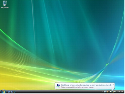
Step 7. Click the notification icon, and you will be prompted to enter user credentials.
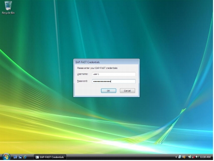
Step 8. Enter the user credentials for authentication. In this example, the username is user1, and the password is cisco123.
Step 9. View the Cisco Secure ACS Passed Authentication log to verify successful client authentication and policy assignment.
Step 10. On the switch, enter the show dot1x interface FastEthernet 0/1 details command to verify the current status of the client.
Step 11. Enter the show vlan command to verify that the switch port has been placed in the correct VLAN.
Task 2: Test Scenario 2
Step 1. Choose Start > All Programs > Accessories, right-click Command Prompt, and choose Run as administrator. Type your administrative credential at the UAC prompt and click Continue.
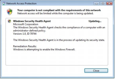
Step 2. Type netsh firewall set opmode disable to disable Windows Firewall. As soon as the command above is issued, the NAP agent is notified that the health state has changed, and it will initiate an EAPoL-Start 802.1x control packet to trigger IEEE 802.1x reauthentication with new health information. As a result of reauthentication, the client is now considered noncompliant; therefore, it is placed in the quarantine VLAN, and the user is notified that the computer does not meet the requirements of the network policy, as shown here.

Step 3. Click this balloon message. Another window appears detailing why the computer does not meet the requirements of the network policy.
Step 4. In this test, Microsoft NPS is configured to perform autoremediation when Windows Firewall is disabled. As a result, when Microsoft NPS detects that the client Windows Firewall is disabled, it tries to reenable the firewall as a remediation process. You will see this process right after you disable Windows Firewall. When the firewall is forcefully enabled as a remediation process, the user will be notified that the remediation process is complete in a balloon message as shown here.

Step 5. Click this balloon message. Another window appears detailing the remediation process, as shown here.
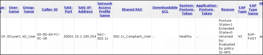
Step 6. View the Cisco Secure ACS Passed Authentication log. You can now see that the client was quarantined once and then placed back in the healthy VLAN immediately after Microsoft NPS performed the remediation process.
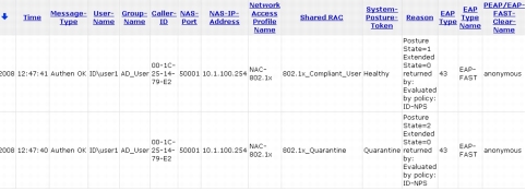
Step 7. Notice in Reason field of the Cisco Secure ACS Passed Authentication log that the Posture State value changed from 2 to 1. Posture State=2 means that the SoH information sent from the client PC did not meet the policy requirements configured on Microsoft NPS. Posture State=1 means that the client passed all health checks on Microsoft NPS.
Task 3: Test Scenario 3
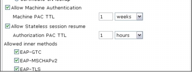
Step 1. Verify that machine authentication is enabled in Cisco Secure ACS by navigating on the Cisco Secure ACS web console to System Configuration > Global Authentication Setup > EAP-FAST Configuration.
Step 2. In the EAP-FAST settings, verify that Allow Machine Authentication is enabled.
Step 3. Verify that your Vista supplicant configuration is set to perform both machine and user authentication by entering the following command at the command prompt in Vista:
Step 4. Reboot your Windows Vista machine and wait for the CTRL + ALT + DELETE message to appears.
Step 5. On the switch, enter the show dot1x interface FastEthernet 0/1 details command to verify the current status of the client.
Step 6. Enter the show vlan command to verify that the switch port has been placed in the correct VLAN.
Step 7. Notice that although machine authentication succeeds, the Vista client is placed in quarantine VLAN 40. This behavior occurs because the Windows Vista supplicant service starts much earlier than the NAP agent. When authentication requests SoH information, the NAP agent is not available, and therefore no SoH information is sent to Cisco Secure ACS. Cisco Secure ACS performs authentication first against Active Directory; however, because there is no SoH information, it uses the Posture Optional method and immediately assigns the Quarantine token.
This behavior is why the NAD receives the quarantine VLAN for machine authentication. As soon as the NAP agent starts, it reevaluates the system and tries to reauthenticate the device. The following are the results of the show dot1x interface FastEthernet0/1 detail command after the NAP agent starts upon successful machine authentication, and also after the successful user authentication.
Here is the Cisco Secure ACS log showing the flow of those authentications by device and user.
Task 4: Test Scenario 4
Step 1. The profile can be edited using a text editor or an Extensible Markup Language (XML) editor. To export the default configuration profile, use following command:
Example: netsh lan export profile folder="c:\profiles" interface="LAN"
Use the following command to reimport the configuration profile after editing is completed:
Example: netsh lan add profile filename="c:\profiles\LAN.xml" interface="LAN"
Step 2. On the Windows Vista Client, choose Start > All Program > Accessories > Command Prompt. In the command prompt console, type netsh to enter netsh command mode.
Step 3. Type lan and show profile. Verify that the output from the previous task shows the values shown here.
Step 4. Enter the command shown here to export the profile (for this operation, the wired interface name is Local Area Connection; if the name of your interface is different, change the name here accordingly). After you export the profile, exit the netsh command line by typing bye and then start editing the XML profile with Notepad or some other text editor.
Step 5. When editing the Local Area Connection.xml file, add <authMode>machine</authMode> immediately before the <EAPConfig> element in this XML file as shown here.
|
--- Skipped ---
<OneX xmlns="http://www.microsoft.com/networking/OneX/v1">
<cacheUserData>false</cacheUserData>
<authMode>machine</authMode>
<EAPConfig>
--- Skipped ---
|
Step 6. After editing the XML file, save the change and close the text editor. Go back to the command prompt console and enter netsh lan mode.
Step 7. Type the following command to add the edited profile to the interface:
The profile was added successfully on the interface Local Area Connection.
Step 8. Verify your change in authMode so that only machine authentication is enabled.
Step 9. Reboot your Windows Vista machine and wait for the CTRL + ALT + DELETE message to appear.
Step 10. On the switch, enter the show dot1x interface FastEthernet 0/1 details command to verify the current status of the client.
Step 11. Enter the show vlan command to verify that the switch port has been placed in the correct VLAN.
Step 12. Notice that although machine authentication succeeds, the Vista client is placed in quarantine VLAN 40. This behavior occurs because the Windows Vista supplicant service starts much earlier than the NAP agent. When authentication requests SoH information, the NAP agent is not available, and therefore no SoH information is sent to Cisco Secure ACS. Cisco Secure ACS performs authentication first against Active Directory; however, because there is no SoH information, it uses the Posture Optional method and immediately assigns the Quarantine token. This behavior is why the NAD receives the quarantine VLAN for machine authentication. As soon as the NAP agent starts, it reevaluates the system and tries to reauthenticate the machine. Here are the results of the show dot1x interface FastEthernet0/1 detail command after the NAP agent starts.
Note: This is the setting for machine authentication only. Therefore, IEEE 802.1x authentication is not triggered upon Windows user logon.
Tuning the Windows Vista Supplicant Function
|
<?xml version="1.0" ?>
- <LANProfile xmlns="http://www.microsoft.com/networking/LAN/profile/v1">
- <MSM>
- <security>
<OneXEnforced>false</OneXEnforced>
<OneXEnabled>true</OneXEnabled>
- <OneX xmlns="http://www.microsoft.com/networking/OneX/v1">
<cacheUserData>false</cacheUserData>
<supplicantMode>compliant</supplicantMode>
<authMode>machine</authMode>
- <singleSignOn>
<type>preLogon</type>
<maxDelay>10</maxDelay>
<allowAdditionalDialogs>true</allowAdditionalDialogs>
<maxDelayWithAdditionalDialogs>10</maxDelayWithAddtionalDialogs>
<userBasedVirtualLan>true</userBasedVirtualLan>
</singleSignOn>
- <EAPConfig>
------- omitted ---------
</EAPConfig>
</OneX>
</security>
</MSM>
</LANProfile>
|
Task 1: Configure Supplicant with Group Policy
Step 1. On a server running Windows Server 2003, copy the adprep directory, located in <yourDVDdrive>:\sources\adprep on the Windows Server 2008 DVD, to a temporary directory on your local system. (You can create a temporary directory named temp on your C drive on a server running Windows Server 2003 and copy adprep to the directory.)
Step 2. On Windows Server 2003, launch the command prompt (choose Start > All Programs > Accessories > Command Prompt) and open the adprep directory you just copied from Windows Server 2008 DVD (cd c:\temp\adprep).
Step 3. The adprep directory contains a program called adprep.exe. You will use this program to extend your Active Directory schema. Note that this command will be applied to your Active Directory schema, so use this command with caution. We highly recommended that you test this upgrade in your testing environment first. At the command prompt, enter the following command:
Step 4. At the command prompt, you will be asked to confirm the command and change. Confirm the command by typing C and pressing the Enter key.
Step 5. On the Windows Vista SP1 client where the Cisco EAP-FAST Module is installed, you need to install another program called Group Policy Management Console (GPMC), so you can make changes to Active Directory group policy. By default, GPMC is not installed on Windows Vista SP1. From Windows Vista SP1, GPMC is included in a package called Remote Server Administrator Tool (RSAP), which can be found as KB941314 at the Microsoft website. You have to install RSAP first and enable GPMC as a Windows component. Download the RSAP installer to the desktop. Click Windows6.0-KB941314-x86 installer and follow the instructions to complete RSAP installation.
Step 6. After installing RSAP, choose Start > Control Panel > Programs > Programs and Features and select Turn Windows features on or off. Then choose Remote Server Administration Tools > Feature Administration Tools and select Group Policy Management Tools. Click OK to enable GPMC.]
Step 7. With GPMC installed, you can browse Group Policy on your Active Directory domain from Windows Vista SP1. Start GPMC by choosing Start > All Programs > Accessories > Run and typing gpmc.msc. On the User Account Control screen, click Continue to display the Group Policy Management screen. (This example assumes that you are running this program from an account with administrative privileges.)
Step 8. As shown in the following screenshot, browse to your domain and select Default Domain Policy. On the right pane of the screen, select the Settings tab and right-click Computer Configuration (Enabled). In the context menu, choose Edit.
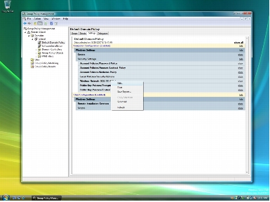
The Local Group Policy Editor screen will appear. Although the default domain policy is used to configure group policy in this document, we recommend that you configure a separate GPO that can be applied to only NAC-NAP computers.
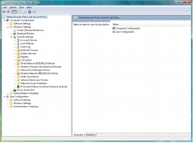
Step 9. In the Local Group Policy Editor window, choose Computer Configuration > Windows Settings > Security Settings to display the Wireless / Wired Interface Policies pane.
Note: This documentation discusses only wired interface policy and its EAP-FAST configuration.
Step 10. Right-click Wired Network (IEEE 802.3) Policies in the policy tree and choose Create a New Windows Vista Policy from the context menu
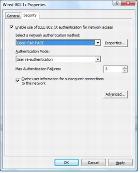
Step 11. On the General tab, in the Policy Name field, type Wired-802.1x.
Step 12. On the Security tab, verify that Enable use of IEEE 802.1x authentication for network access is selected. From the Select a network authentication method pull-down menu, choose Cisco: EAP-FAST. Change the value for Max Authentication Failures to 3. For Authentication Mode, choose User re-authentication from the pull-down menu. This selection will enable both user and machine authentication (equivalent to the <authMode>userOrMachine</authMode> element in an XML-based profile).
Note: Max Authentication Failure is set to 1 by default. This setting prevents a user from reentering his or her credentials when invalid credentials are provided at the initial prompt.
Step 13. If you click the Properties button on the Security tab, the EAP-FAST Configuration screen will appear. You can configure EAP-FAST settings centrally using this group policy configuration tool. For EAP-FAST settings, follow the steps described in the "Windows Vista Client Configuration" section earlier in this document.
Step 14. If you click Advanced button on the Security tab, you'll see the available configuration options for the supplicant. Configure the supplicant as in the following screenshot.
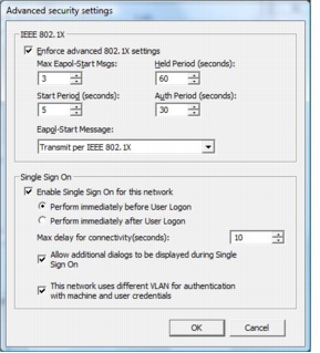
Step 15. As described earlier, Single Sign On can be configured in detail, using group policy. Use the preceding screenshot to configure your group policy setup.
Step 16. After you finish your configuration, exit the GPMC tool.
Step 17. After you finish configuring group policy, you can provision your configuration to the local Windows Vista machine. To do this, run the gpupdate tool to reflect your policy change on the domain to your local system.
Troubleshooting the NAC-NAP Solution
NAC-NAP Troubleshooting Overview
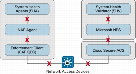
Figure 3. Possible Failure Points in the NAC-NAP Architecture
Failure with No Authentication Record in Cisco Secure ACS Log
• Make sure that required AAA commands are configured properly. Required AAA commands are listed in the "IEEE 802.1x Network Access Device Configuration" section of this guide. If AAA commands are not properly configured, there will be no RADIUS communication between the authenticator and the authentication server, and hence there will be no record in the Cisco Secure ACS log.
• Make sure on the switch or access point that RADIUS servers are configured with the correct addresses and port numbers. If the switch or access point (authenticators) is not sending the authentication request packet to the correct RADIUS server (Cisco Secure ACS), then there will be no record in the Cisco Secure ACS log. If the IP address and port numbers of the RADIUS server are correct but the RADIUS shared key is incorrectly configured, there will be a record in the Cisco Secure ACS Failed Attempt log with the authentication failure code "Invalid message authenticator in EAP request."
• If you have multiple Cisco Secure ACSs in an authenticator configuration, check them all for the log. There is a chance that the log is recorded on another Cisco Secure ACS when multiple Cisco Secure ACSs are running behind a server load-balancing mechanism.
Failure with Authentication Record in Cisco Secure ACS Log
Troubleshooting Client Software
When EAP-FAST Posture Validation Is Not Enabled
When NAP Agent Is Not Enabled
When EAP Enforcement Client Is Not Enabled
When System Health Agent Is Not Running
|
AFC |
Reason |
|
None |
Authentication does not fail. The information is recorded in the Cisco Secure ACS Passed Authentication log. |
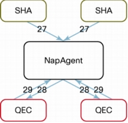
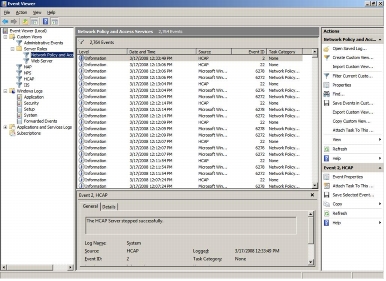
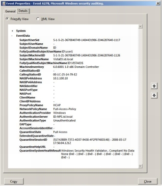
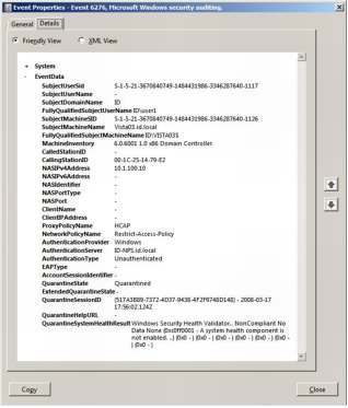
Figure 4. NAP Transaction and Event Log IDs
1. Choose Start > All Programs > Administrative Tools and launch Event Viewer.
2. Under Event Viewer (Local) on the left side of the screen, navigate to Applications and Services Logs > Microsoft > Windows > Network Access Protection, right-click Operational, and choose Filter Current Logs.
3. On the Filter tab, from the Event sources pull-down menu, choose Network Access Protection.
4. In the Include/Excludes Event IDs section, type 6-10, 12, 28, 29 to filter events to those related to NAP in the text box and click OK.
When Supplicant Fails
Note: Wired AutoConfig service is disabled by default and must be manually started. The commands shown here enable the supplicant and configure service so that it starts automatically when the client PC is booted.
|
C:\Windows\system32>sc config dot3svc start= auto
C:\Windows\system32>sc config wlansvc start= auto
C:\Windows\system32>net start dot3svc
C:\Windows\system32>net start wlansvc
|
When EAP-FAST Module Is Not Installed

Troubleshooting IEEE 802.1x Authenticator
IEEE 802.1x Logging and Debugging on a Switch
|
debug dot1x {all | errors | events | feature | packets | registry | state-machine}
no debug dot1x {all | errors | events | feature | packets | registry | state-machine}
|
Authorization Failures on Authenticator (Switch)
When Authorization Command Is Not Configured
• Session-Timeout (27)
• Termination-Action (29)
• Tunnel-Type (64)
• Tunnel-Medium-Type (65)
• Tunnel-Private-Group-ID (81)
When Authorization Mismatch Occurs
Failure in Communication with RADIUS Server
Troubleshooting with Cisco Secure ACS Passed Authentication Log
Troubleshooting Microsoft Network Policy Server
Event Logs
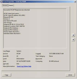
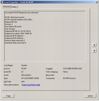
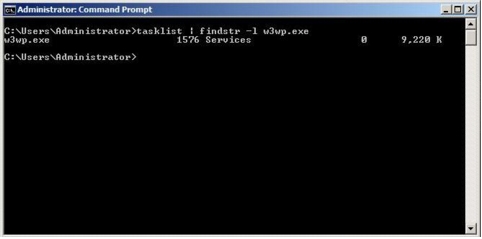
Verification That HCAP Is Running on Microsoft NPS
Troubleshooting NAP
Event Logs
Tracing
1. Open a command prompt in an elevated mode.
2. If the directory %systemroot%\tracing\nap does not exist, create it with the command mkdir %systemroot%\tracing\nap.
3. At the command prompt, enter logman start qagentrt -p {b0278a28-76f1-4e15-b1df-14b209a12613} 0xFFFFFFFF 9 -o %systemroot%\tracing\nap\qagentrt.etl -ets.
4. Run the scenario to capture the trace.
5. To stop tracing, at the command prompt enter logman stop qagentrt -ets.
6. Copy %systemroot%\tracing\nap\qagentrt.etl to another folder so that it can be sent to Microsoft.
Troubleshooting Microsoft Network Policy Server
Accounting Logs
Event Logs
Tracing
1. At the command prompt in an elevated mode, run netsh ras set tracing * enable. This command will start tracing.
2. Restart Microsoft NPS.
3. At the command prompt, enter net stop ias.
4. At the command prompt, enter net start ias.
5. Reproduce the problem. This will generate a trace file of the problem.
6. Copy %windir%\tracing\IAS*.log to another folder so that it can be sent to Microsoft.
7. At the command prompt, enter netsh ras set tracing * disable.
8. Restart Microsoft NPS.
9. At the command prompt, enter net stop ias.
10. At the command prompt, enter net start ias.
Troubleshooting HCAP Server
Event Logs
Tracing
1. At the elevated command prompt, enter logman start hcapext -p {af000c3b-46c7-4166-89ab-de51df2701ee} 0xFFFFFFFF 9 -o %systemroot%\tracing\hcapext\hcapext.etl -ets.
2. Reproduce the problem. This will generate the trace file of the problem.
3. Copy %systemroot%\tracing\hcapext\hcapext.etl to another folder so that it can be sent to Microsoft.
4. To stop tracing, at the command prompt enter logman stop hcapext -ets.
Troubleshooting Wireless AutoConfig Service
Event Logs
Tracing
1. From an elevated command prompt, enter netsh WLAN set tracing yes. This will start tracing.
2. Reproduce your problem.
3. To disable tracing, at the command prompt enter netsh WLAN set tracing no. After executing this command, wait for control to return to the command window (postprocessing converts the files into readable text).
4. Copy the entire C:\Windows\tracing\wireless folder, including all subdirectories, to another folder so that it can be sent to Microsoft.
Troubleshooting Wired AutoConfig Service
Event Logs
Tracing
1. From an elevated command prompt, enter Netsh LAN set tracing yes. This will start tracing.
2. Reproduce your problem.
3. To disable tracing, at the command prompt enter netsh LAN set tracing no. After executing this command, wait for control to return to the command window (postprocessing converts the files into readable text).
4. Copy the entire C:\Windows\tracing\wired folder, including subdirectories, to another folder so that it can be sent to Microsoft.
Troubleshooting Cisco EAP-FAST Module
Tracing
1. Choose Start > All Programs > Accessories.
2. Right-click Command Prompt and choose Run as Administrator.
3. At the prompt, enter the following command to configure and start logging: wevtutil.exe si Cisco-EAP-FAST/Debug /e:true Network Policy Server.
4. Reproduce the problem with the Cisco EAP-FAST Module.
5. At the prompt, enter the following command to stop the logging: wevtutil.exe sl Cisco-EAP-FAST/Debug /e:false.
6. Browse to C:\Windows\System32\Winevt\Logs\ and you can find the log file Cisco\EAP-FAST%4Debug.etl.
Note: After the .etl file is obtained, you can view this log with Event Viewer. After logging is turned off, all the internal buffers for logs are flushed. Also, you must stop logging before you can analyze the .etl file. If you must shut down the device on which logging was running before logging finishes, logging resumes after you reboot. If logging is started either automatically or manually, however, the logs are cleared.