|
|
Data Sheet
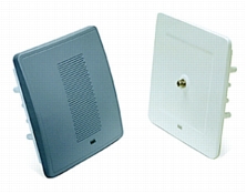
Cisco Aironet 1400 Series Wireless Bridge
OVERVIEW
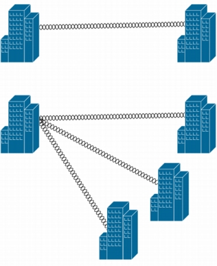
• Support for both point-to-point or point-to-multipoint configurations (Figure 1)
• Industry leading range and throughput, supporting data rates up to 54 Mbps
• Enhanced security mechanisms based on 802.11 and 802.11i standards
• Ruggedized enclosure optimized for harsh outdoor environments with extended operating temperature range
• Integrated or optional external antennas for flexibility in deployment
• Designed specifically for ease-of-installation and operation
BRIDGING FIXED NETWORKS
1. The sole connection
2. The primary connection with an additional technology such as a T1 line providing redundancy, or
3. As a back up solution for additional resiliency in conjunction with other technologies such as fiber optics.
• Local Government-Backbone (backhaul) portion of community-based municipal networks such as public safety networks, or any fixed network location
• Education-Higher education campus building interconnects and K-12 schools within a metropolitan area
• Healthcare-Hospital campuses and physician offices
• Enterprise Campus-Building-to-building links (point-to-point or point-to-multipoint), or any situation where a company needs to expand across an area where right-of-way is not possible
• Service Provider-Backhaul to aggregate multiple lower-speed links into a higher speed link
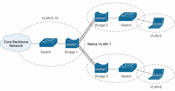
Figure 1. Point-to-Point and Point-to-Multipoint Applications
Mobile Networks and Wireless Bridges
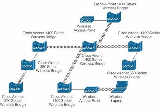
Figure 2. Public Safety Network Utilizing Wireless Bridges
ROI
High Performance
Security
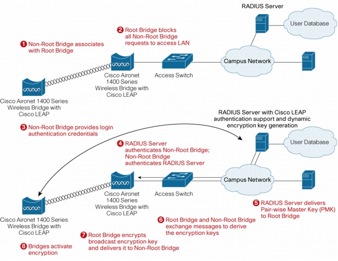
Figure 3. Wireless Bridge Security with the Cisco Wireless Security Suite
Intelligent Network Services
Figure 4. VLAN Configuration for Wireless Bridges
Flexible
• 9.0 dBi vertically polarized omni antenna
• 9.5 dBi sector antenna with support for vertical or horizontal linear polarization
• 28.0 dBi dish antenna with support for vertical or horizontal linear polarization
Ease of Use
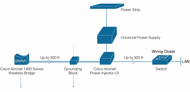
• The Cisco Aironet Power Injector LR for supplying power to the bridge without expensive electrician costs (Figure 5). The power injector also extends the distance the 1400 Series Wireless Bridge can be installed from the network. (Figure 6)
• The Cisco Aironet 1400 Series Multifunction Mount, with its innovative design, to provide greater ease of installation and flexibility. The mount comes complete with stainless steel hardware to improve corrosion resistance.
• Two lengths of shielded Dual RG-6 cables and a building entry point grounding block, all with F-Type connectors for use with the Power Injector LR and connection to the bridge unit.
• A power supply and cord, enough coaxial sealant for all outdoor connectors, and corrosion-proof gel to protect grounding connections.
Figure 5. Cisco Aironet Power Injector
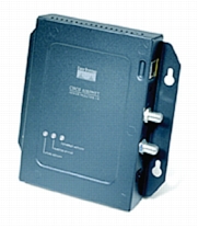
Figure 6. Power Injector Distance Extension
Advanced Management Features
Table 1. Features and Benefits
|
Features |
Benefits |
|
802.11a radio with 24 dBm (250 mW) maximum transmit power, -70 dBm receive sensitivity at 54 Mbps data rate1 |
The 5.8 GHz radio in the Cisco Aironet 1400 Series offers superior radio performance that results in industry-leading range. The greater the range, the higher the supported data rate or the more reliable the link at a given data rate. |
|
Industry-leading security, network management, and software feature set |
The Cisco Aironet 1400 Series software builds on the feature-rich, customer-driven Cisco Aironet software and the Cisco Wireless Security Suite, including 802.1X support with mutual authentication and dynamic encryption keys with TKIP; management through SNMP, Telnet, and Web browsers. |
|
Fully weatherized metal housing and extended operating temperature (-30 to 55oC or -22 to 131oF) |
The rugged weatherproof design of the Cisco Aironet 1400 Series provides flexibility for deployment in a variety of settings. The rugged features and broad operating temperature range support deployment in factories, warehouses, and the outdoors. |
|
The Cisco Aironet Power Injector LR |
The Power Injector LR converts the standard 10/100 baseT Ethernet category 5 RJ-45 interface that is suitable for weather-protected areas to a dual F-Type connector interface for dual coax cables that are more suitable for harsh outdoor environments. While providing a 100baseT interface to the Cisco Aironet 1400 Series, the Power Injector LR also provides power to the unit over the same cables with a power discovery feature that protects other appliances from damage should they accidentally be connected. As an added benefit to the installer, Auto MDIX is built in, allowing the dual cables to be swapped and while maintaining the same functionality. To support longer cable runs from your infrastructure network switch or router, the Power Injector LR is designed to accommodate 100 m coaxial cable run plus 100 m of indoor cat5 cable, to enable total cable runs up to 200 meters. Lightning and surge protection is also included at the F-Type connector interface to provide added protection to your network infrastructure devices. |
|
Flexible mounting with multifunction mount or optional roof/wall mount |
The Cisco Aironet 1400 Series Multifunction Mount allows the captured antenna Cisco Aironet 1400 Series to provide either horizontal or vertical polarization. With its quick-hang feature, the mount will support the weight of the bridge during the alignment process. To assist the installation, hoisting rings are attached to the mount. The mount will interface to poles or masts from 1.5 in. to 2.5 in. while allowing for elevation and azimuth alignment. For the connectorized version, the mount provides a wall mount mechanism. The captured antenna Cisco Aironet 1400 Series can be mounted to a wall, roof, or other flat surface with the addition of the optional Cisco Aironet 1400 Series Roof/Wall Mount kit. |
|
Wireless root bridge |
The wireless root bridge role provides the Cisco Aironet 1400 Series with support for both point-to-point or point-to-multipoint bridging |
|
Wireless non-root bridge |
The wireless non-root bridge allows the Cisco Aironet 1400 Series to operate as the remote node in a point-to-point or point-to-multipoint bridge network. |
|
Wireless packet concatenation |
The concatenation of smaller packets into larger ones allows the Cisco Aironet 1400 Series to more efficiently utilize the wireless medium and provide higher overall data throughputs. |
|
Wireless link distance adjustment |
The link distance parameter allows the user to tune the carrier sense multiple access with collision avoidance (CSMA/CA) parameters for the particular range to maximize performance. |
|
Wireless programmable clear channel assessment |
With a programmable clear channel assessment, the Cisco Aironet 1400 Series can be configured to the particular background interference level found in your environment for reduced contention overhead with other wireless systems. |
|
Antenna alignment assistance |
The Cisco Aironet 1400 Series Wireless Bridge provides an auto-configuration and installation mode for out of the box deployment of point to point links without the need for a configuration via telnet, File Transfer Protocol (FTP), or SNMP. This mode drives LEDs and a Received Signal Strength Indicator (RSSI) port with a voltage output proportional to received signal strength for use in the installation and alignment process. This frees up the installers to perform their installation process and verify the link quality without requiring Cisco IOS Software or data networking knowledge. |
|
Diagnostic LEDs |
Provide alignment feedback to the installer and diagnostic information to troubleshooters directly at the antenna without the use of a computer. Diagnostic information is also provided on the Power Injector LR LEDs |
|
16 megabytes of flash memory |
Memory space for future firmware upgrades to support new 802.11 standards and advanced features. |
|
One N-Type connector for external antenna connection |
The N-Type connector is the industry standard for higher performance RF systems in an outdoor environment and is compatible with the Cisco® line of optional 5.8 GHz antennas, enabling wireless bridging professional installers to customize radio coverage for specific deployment scenarios. |
|
Easy weather sealing and grounding |
The Cisco Aironet 1400 Series provides standard N-Type and F-Type coaxial cable connectors for easy and reliable weather sealing and grounding. A coaxial sealant is provided with each system, along with a standard grounding block to allow the installer to meet National Electric Code guidelines. |
|
124 dBm transmit power only available in FCC configuration units
|
Table 2. Cisco Aironet 1400 Series Wireless Bridge System Specifications
|
AIR-BR1410A-x-K9 |
AIR-BR1410A-A-K9-N |
|
|
Frequency band |
5.725 to 5.825 GHz (FCC UNII 3) |
5.725 to 5.825 GHz (FCC UNII 3) |
|
Wireless modulation |
Coded Orthogonal Frequency Division Multiplexing (COFDM) |
Coded Orthogonal Frequency Division Multiplexing (COFDM) |
|
Media access protocol |
Carrier Sense Multiple Access with Collision Avoidance (CSMA/CA) |
Carrier Sense Multiple Access with Collision Avoidance (CSMA/CA) |
|
Modulation |
• BPSK @ 6 and 9 Mbps
• QPSK @ 12 and 18 Mbps
• 16-QAM @ 24 and 36 Mbps
• 64-QAM @ 48 and 54 Mbps
|
• BPSK @ 6 and 9 Mbps
• QPSK @ 12 and 18 Mbps
• 16-QAM @ 24 and 36 Mbps
• 64-QAM @ 48 and 54 Mbps
|
|
Non-overlapping channels |
4 |
4 |
|
Receive sensitivity (10% PER with 3200 byte packets) |
• 6 Mbps: -83 dBm
• 9 Mbps: -83 dBm
• 12 Mbps: -83 dBm
• 18 Mbps: -82 dBm
• 24 Mbps: -79 dBm
• 36 Mbps: -76 dBm
• 48 Mbps: -72 dBm
• 54 Mbps: -70 dBm
|
• 6 Mbps: -83 dBm
• 9 Mbps: -83 dBm
• 12 Mbps: -83 dBm
• 18 Mbps: -82 dBm
• 24 Mbps: -79 dBm
• 36 Mbps: -76 dBm
• 48 Mbps: -72 dBm
• 54 Mbps: -70 dBm
|
|
Maximum operational receive level |
-19 dBm |
-19 dBm |
|
Maximum survivable receive level |
0 dBm |
0 dBm |
|
Available transmit power settings |
• AIR-BR1410A-A-K9
• 250 mW (24 dBm)
• 200 mW (23 dBm)
• 155 mW (22 dBm)
• 125 mW (21 dBm)
• 60 mW (18 dBm)
• 30 mW (15 dBm)
• 15 mW (12 dBm)
• AIR-BR1410A-K-K9
• 155 mW (22 dBm)
• 125 mW (21 dBm)
• 60 mW (18 dBm)
• 30 mW (15 dBm)
• 15 mW (12 dBm)
• AIR-BR1410A-Z-K9
• 20 mW (13 dBm)
• 10 mW (10 dBm)
• 8 mW (9 dBm)
• 6 mW (8 dBm)
• 5 mW (7 dBm)
• 2.5 mW (4 dBm)
• AIR-BR1410A-E-K9
• 5 mW (7 dBm)
• 2.5 mW (4 dBm)
|
• 250 mW (24 dBm)
• 200 mW (23 dBm)
• 155 mW (22 dBm)
• 125 mW (21 dBm)
• 60 mW (18 dBm)
• 30 mW (15 dBm)
• 15 mW (12 dBm)
|
|
Note: Maximum power setting will vary according to individual country regulations |
||
|
Point-to-point range1 |
• Americas
• 8.5 miles (14 km) @ 54 Mbps
• 16 miles (26 km) @ 9 Mbps
• Korea
• 5.5 miles (9 km) @ 54 Mbps
• 11.25 miles (18.25 km) @ 9 Mbps
• Australia & New Zealand
• 3.5 miles (5.75 km) @ 54 Mbps
• 9.5 miles (15.25 km) @ 9 Mbps
• Ireland & China
• 1.75 miles (2.75 km) @ 54 Mbps
• 7.25 miles (11.5 km) @ 9 Mbps
|
• Americas
• 13 miles (21 km) @ 54 Mbps
• 23 miles (37 km) @ 9 Mbps
• (Antennas are 28 dBi dish)
|
|
Point-to-multipoint range (sector antenna at root)3 |
• Americas
• 2.75 miles (4.5 km) @ 54 Mbps
• 8.5 miles (14 km) @ 9 Mbps
• Korea
• 1 mile (1.75 km) @ 54 Mbps
• 5 miles (8 km) @ 9 Mbps
• Australia & New Zealand
• 0.75 miles (1.2 km) @ 54 Mbps
• 3.25 miles (5.25 km) @ 9 Mbps
• Ireland & China
• 0.4 miles (0.6 km) @ 54 Mbps
• 1.75 miles (2.75 km) @ 9 Mbps
|
• Americas
• 4.25 miles (7 km) @ 54 Mbps
• 11 miles (18 km) @ 9 Mbps
• (Non-root antenna is 28 dBi dish)
|
|
Antenna |
Captured Linear Polarization; 22.5 dBi gain2: 10° E-plane by 12° H-plane beamwidth |
One N-Type connector for professional installations (antennas sold separately) |
|
Security |
Cisco Wireless Security Suite, including: • Authentication
• 802.1X support including LEAP to yield mutual authentication and dynamic per-user, per-session encryption keys
• Encryption
• Support for static and dynamic IEEE 802.11 WEP keys of 40 bits and 128 bits
• WPA TKIP and Cisco TKIP enhancements: key hashing (per packet keying), Message Integrity Check (MIC), and broadcast key rotation
|
|
SNMP compliance |
v1 and v2 |
v1 and v2 |
|
1The distances referenced here are approximations and should be used for estimation purposes only.
2AIR-BR1410A-K-K9 has 20 dBi gain
|
Table 3. Cisco Aironet 1400 Series Wireless Bridge Product Specifications
|
AIR-BR1410A-x-K9 |
AIR-BR1410A-A-K9-N |
Power Injector LR |
|
|
Status LEDs |
Four LEDs: • Install
• Radio
• Status
• Ethernet
|
Four LEDs: • Install
• Radio
• Status
• Ethernet
|
Four LEDs: • Power ON
• Injector status
• LAN Ethernet status
• Bridge Ethernet status
|
|
RSSI port |
BNC connector DC Voltage port (0VDC to 2.7 VDC) |
BNC connector DC Voltage port (0VDC to 2.7 VDC) |
- |
|
Uplink |
100 Mbps over dual coaxial cables |
100 Mbps over dual coaxial cables |
10/100BaseT Ethernet |
|
Configuration support |
Telnet, HTTP, FTP, TFTP, SNMP |
Telnet, HTTP, FTP, TFTP, SNMP |
- |
|
Compliance |
Standards • Safety:
• UL 60950
• CSA C22.2 No. 60950-00
• IEC 60950
• EN 60950
• Radio Approvals:
• FCC Part 15.207, 15.407 & 15.209 Class B
• ICES-003 Class B (Canada)
• Canada DGTP-010
• FCC Bulletin OET-65C
• Industry Canada RSS-102, RSP100, RSS 210 Issue 5
• EMI and Susceptibility (Class B):
• FCC Part 15.107 & 15.109 Class B
• ICES-003 Class B (Canada)
• EN 55022 Class B
• EN 55024
|
Standards • Safety:
• UL 60950
• CSA C22.2 No. 60950-00
• IEC 60950
• EN 60950
• NEMA 4
• Radio Approvals:
• FCC Part 15.207, 15.407
• & 15.209 Class B
• ICES-003 Class B (Canada)
• Canada DGTP-010
• FCC Bulletin OET-65C
• Industry Canada RSS-102, RSP100, RSS 210 Issue 5
• EMI and Susceptibility (Class B):
• FCC Part 15.107 & 15.109 Class B
• ICES-003 Class B (Canada)
• EN 55022 Class B
• EN 55024
|
Standards • Safety:
• UL 60950
• CSA C22.2 No. 60950-00
• IEC 60950
• EN 60950
• EMI and Susceptibility (ClassB):
• FCC Part 15.107 & 15.109 Class B
• ICES-003 Class B (Canada)
• EN 55022 Class B
• EN 55024
|
|
Country compliance |
Customers are responsible for verifying approval for use in their country. Please see http://www.cisco.com/go/aironet/compliance to verify approval and to identify the regulatory domain that corresponds to a particular country. Not all regulatory domains have been approved. As they are approved, the part numbers will be available on the Global Price List. |
||
|
Dimensions |
11.4in x 11.4in x 4.2in (29cm x 29cm x 11cm) |
11.6in x 11.6in x 3.6in (29cm x 29cm x 9cm) |
6.7in x 6.3in x 1.3in (17cm x 16cm x 3cm) |
|
Weight |
11 lbs. (5 kg) |
10 lbs. (5 kg) |
1.4lbs. (0.6kg) |
|
Operational temperature |
-30º to +55ºC (-22º to +131ºF) |
-30º to +55ºC (-22º to +131ºF) |
0º to +50ºC (32º to 122ºF) |
|
Storage temperature |
-40º to +85ºC (-40º to +185ºF) |
-40º to +85ºC (-40º to +185ºF) |
-40º to +70ºC (-40º to +158ºF) |
|
Operational altitude |
4206 m (13,800 ft.) |
4206 m (13,800 ft.) |
4206 m (13,800 ft.) |
|
Storage altitude |
4877 m (16,000 ft.) |
4877 m (16,000 ft.) |
4877 m (16,000 ft.) |
|
Humidity |
0 to 100% (condensing) |
0 to 100% (condensing) |
0 to 90% (non-condensing) |
|
Vibration |
0.001 G2/Hz from 5-100 Hz |
0.001 G2/Hz from 5-100 Hz |
0.001 G2/Hz from 5-100 Hz |
|
Storage vibration |
0.01 G2/Hz from 5-100 Hz |
0.01 G2/Hz from 5-100 Hz |
0.01 G2/Hz from 5-100 Hz |
|
Enclosure |
Aluminum with environmentally sealed plastic radome |
NEMA-4, aluminum |
Metal case |
|
AC power |
Not Required as uses DC voltage from Power Injector |
Not Required as uses DC voltage from Power Injector |
100 to 240 VAC +/- 10% (power supply) |
|
DC power |
48 VDC +/-2V |
48 VDC +/-2V |
48 VDC +/-2V |
|
Warranty |
One year |
One year |
One year |