Cisco Security Manager (CSM) can be used to deploy and manage Group Member (GM) and Key Server (KS) configurations efficiently. CSM allows painless rapid deployment of GMs. CSM is an enterprise-class tool which allows the administrator to easily deploy and manage huge number of GMs.
This document provides step by step procedure for deploying GETVPN GMs and KSs running IOS version 12.4 22T using CSM version 3.3. Before using CSM for deploying new GMs, get at least 2 GMs and 1 Key Server (KS) working. This will be helpful to discover configuration from the working GM and KS and use it for creating master configuration devices for deployment.
1 GETVPN Deployment using CSM overview
1.1 Network Topology
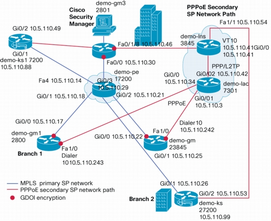
Figure 1. Demo GETVPN Network Topology
GETVPN example deployment setup consists of three GMs (Group Members) and two KS (Key Server) are included in the setup. "demo-pe1" simulates the MPLS primary SP network. One Key server is located in the Headquarters. Other Key server is connected behind GM in one of the branch. Both KSs have path to primary MPLS SP network and secondary PPPoE SP network.
GMs between branches and headquarters are also connected via secondary PPPoE service provider network. This secondary network will be used when there is network outage in primary SP network. GM between branches is connected to demo-lac via PPPoE interface. PPPoL2TP tunnel connects between demo-lac and demo-lns.
GDOI encryption is done on the customer network side in the GM routers. Traffic flowing through the interface connected to primary SP network and the interface connected to the secondary service provider network are GDOI encrypted.
KS1 and KS2 are connected to both MPLS and PPPoE networks. GMs encrypt traffic using GDOI group GETVPN-DEMO-MPLS for MPLS network and encrypt traffic GETVPN-DEMO-PPPOE GDOI group for PPPoE network
Following table summarizes GDOI groups and IP addresses for the GM interfaces:
GDOI group
GDOI encryption in demo-gm1 interface
GDOI encryption in demo-gm2 interface
GDOI encryption in demo-gm3 interface
GETVPN-DEMO-MPLS GDOI group for primary MPLS network (LAN)
Gi0/0 10.5.110.17
Gi0/0 10.5.110.22
Fa0/0 10.5.110.30
GETVPN-DEMO-PPPOE group for secondary SP network (WAN)
Dialer 10 10.5.110.243
Dialer 10 10.5.110.242
Fa0/1/8 10.5.110.46
2. Create GM and KS Master Device in CSM Client
This section describes step by step process of creating master devices by discovering a GETVPN GM (demo-gm1) and KS (demo-ks1) using CSM client. Log into CSM Client. First step involves creating a master GM device. This master GM device will be cloned and used for deploying other GMs. Master GM device is created by discovering an existing GM.
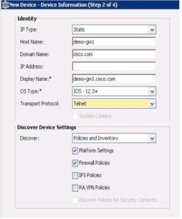
2.1 Discover the GM
Discover configuration from a well working GM. In this example demo-gm1's configuration is discovered.
Start Cisco Security Manager Client from CSM. Log into CSM Client.
From CSM client window select File menu, then select New Device, Select Add Device from Network and click Next.
Discover GM by entering following values as shown below and enter Next:
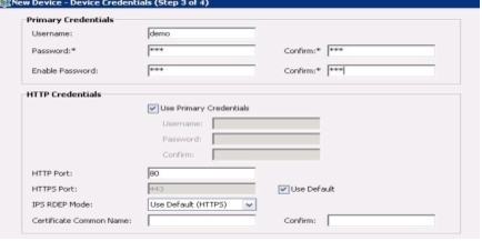
2.2 Device credentials
Enter Device Credentials as shown below, click Next and click Finished.
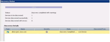
2.3 Check Device Discovery status
Check discovery status of the device. Device should be discovered in CSM client.
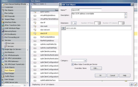
2.4 Add a Text Variable for VLAN 10 IP Address
Add a text variable as follows for making VLAN 10 IP address customizable for every new device. VLAN 10 is private network that changes for every GM. Devices like Personal Computer and phones are connected to VLAN 10. From Tools menu select Policy Object Manager, select Text objects and add VLAN 10 IP variable as follows. Once you enter the value, save and from File menu submit.
2.5 Discover Key Server configuration
Discover configuration of the primary KS demo-ks1 using same process described in sections 2.2.1 to 2.2.3. Select demo-ks1 device and select Platform, Device Admin, Accounts and Credentials menu. Right click and select "Unassign policy". Credentials are not required since all the GETVPN devices are initially configured with user credentials. To save this configuration, select file menu and click "submit". Configuration will not be applied to the device database, until it is submitted.
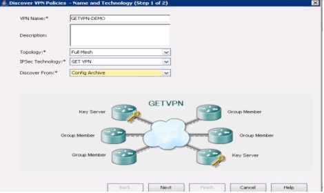
2.6 Discover GETVPN policies
To discover GETVPN policies from GMs and KSs, following needs to be done:
From the "Policy" menu, select "Discover VPN Policies...", fill in name and technology fields as follows:
In this example VPN policies are discovered using existing configuration stored in the CSM after GM and KS are discovered. Alternatively you can discover VPN policies from network by setting "Network" value in the "Discover from" field. End result will be same for both these methods.
Press "Next" button.
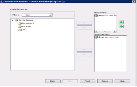
Select the GM and KS devices as shown below:
Press "Finish" button.
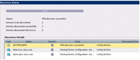
Discovery status screen will show the discovery status as given below:
Press close button and from file menu click "submit".
2.7 Add GETVPN Flexconfig in GM
CLIs that are not supported by CSM needed to be added in Flexconfig.
Process of identifying CLIs that are not supported by CSM is as follows: Select discovered device, right click and preview the full configuration of the discovered device. Then select the discovered device and clone it to a new device and preview configuration of cloned device. The difference between CLIs present in the discovered device configuration and cloned device configuration are the CLIs that are not supported by CSM.
Add missing CLIs that not supported by CSM in demo-getvpn Flexconfig as shown below.:
Select demo-gm1 device.
Select Routing and EIGRP menu, right click and select "Unassign Policy...". EIGRP policy is added in the flexconfig for GM.
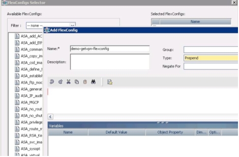
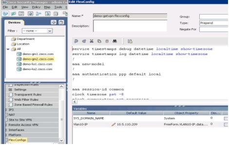
Next select Flexconfigs and Select +. Enter demo-getvpn-flexconfig as Flexconfig name. Select flexconfig type as Prepend. Add following configuration as Flexconfig that is common to all the GMs, press Save and from File menu click submit:
Add the following CLIs in the flexconfig that are not part of the configuration generated by CSM..
There are a few variables you need to add in this Flexconfig.
Procedure for adding $Vlan10-IP: From the Flexconfig page at the first occurrence of this variable: right click, select "Insert Policy object" menu, then select "Text object", Select Vlan10-IP. Text Object Property Selector Window will pop-up. Enter Variable Name as Vlan10-IP. All the other places in Flexconfig where you want to use this variable, simply enter $Vlan10-IP.
Procedure for adding $SYS_DOMAIN_NAME - From the Flexconfig page where you want to enter the domain name, right click and select "Insert System Variables" , "Device" and "SYS_DOMAIN_NAME".
service timestamps debug datetime localtime show-timezone
service timestamps log datetime localtime show-timezone
!
aaa new-model
!
aaa authentication ppp default local
!
aaa session-id common
clock timezone pst -8
clock summer-time pst recurring
!
ip cef
!
ip dhcp pool demo
network $Vlan10-IP 255.255.255.248
domain-name $SYS_DOMAIN_NAME
default-router $Vlan10-IP
!
ip domain name $SYS_DOMAIN_NAME
ip multicast-routing
ip igmp ssm-map enable
no ipv6 cef
!
bba-group pppoe global
!
interface Vlan10
ip address $Vlan10-IP 255.255.255.248
ip pim sparse-mode
ip igmp join-group 239.192.1.190 source 10.5.110.88
ip igmp join-group 239.192.1.190 source 10.5.110.99
ip igmp join-group 239.255.255.249 source 10.5.110.218
ip igmp join-group 239.255.255.250 source 10.5.110.218
no autostate
!
interface FastEthernet0/1/0
switchport access vlan 10
spanning-tree portfast
!
interface FastEthernet1/0
description connected to demo-lac
no switchport
no ip address
ip pim sparse-mode
ip tcp adjust-mss 1452
pppoe enable group global
pppoe-client dial-pool-number 10
!
interface Dialer10
ip address negotiated
ip mtu 1492
ip pim sparse-mode
ip nat outside
ip virtual-reassembly
encapsulation ppp
no ip mroute-cache
dialer pool 10
ppp authentication pap
ppp pap sent-username demo@cisco.com password lab
!
! You can configure EIGRP policy directly in CSM without unassigning EIGRP policy. Following provides
! flexibility to make use of Vlan10_IP variable.
router eigrp 44
network $Vlan10-IP 255.255.255.248
network 10.5.110.240 0.0.0.7
no auto-summary
!
ip pim ssm range 1
ip nat inside source list 10 interface Dialer10 overload
!
access-list 1 permit 239.192.0.0 0.0.255.255
access-list 1 permit 239.255.0.0 0.0.255.255
access-list 10 permit 10.5.110.200 0.0.0.7
dialer-list 10 protocol ip list 10
Once you add the Flexconfig, Select File menu and click "submit".
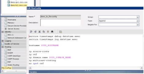
2.8 Add GETVPN Flexconfig in KS
We need to add CLIs not generated by CSM in the Flexconfig.
Add demo_ks_flexconfig Flexconfig as shown below. Select demo-ks1 master device.
Next select Flexconfigs and Select +. Enter demo-ks-flexconfig as Flexconfig name. Select flexconfig type as Append. Add following configuration as Flexconfigs that is common to all the KSs that were not generated by CSM.
Once master (demo-gm1) GM device for a particular platform is created, it can be used for provisioning other GMs with same Platform type. In the example given in this document, Cisco 2851 platform is used.
3.1 Prepare New Device for Deployment as GM
Before pushing GM configuration to new device that needs to be deployed as GM, the device should have network connectivity and user credentials. Here is the minimum configuration needed for demo-gm2 router before deploying configuration from the CSM. Minimum configuration includes the following: IP address, routes, hostname, domain name, and user credentials. Following is the minimum configuration is required to push the configuration from CSM:
service password-encryption
!
hostname demo-gm2
!
enable secret 5 lab
!
username demo password lab
!
interface GigabitEthernet0/0
description Connected to demo-pe1
ip address 10.5.110.22 255.255.255.252
!
router eigrp 44
network 10.5.110.20 0.0.0.3
no auto-summary
!
line con 0
exec-timeout 0 0
stopbits 1
line aux 0
stopbits 1
line vty 0 4
password 7 lab
login
!
3.2 Connect New Device to Network with IP Address
Configure the new device with IP address so that configuration can be pushed from CSM. Very minimum configuration is required. Complete running configuration for this step is given in section 3.1.
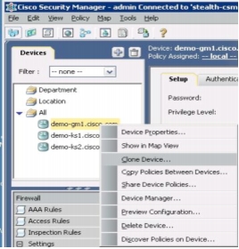
3.3 Clone Device to Deploy New GM
Select the master device "demo-gm1.cisco.com", right click on it and select "clone device" as follows:
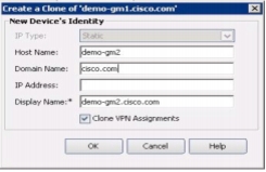
3.4 Clone Device to Deploy New GM
Enter new GM Identity as follows: IP address need to be entered if host name is not published with DNS. After entering required values, click OK.
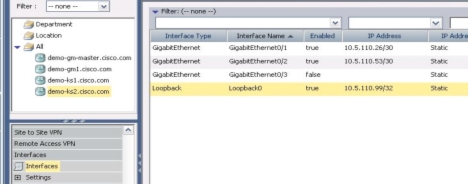
3.5 Change IP Address of Interface
Select dem-gm2 device and select interfaces menu. Change appropriate IP address for Gi0/0 for this GM. Save the Flexconfig. From File menu select submit.
3.6 Select New GM Device and Enter VLAN 10 IP
Select the newly cloned GM and select FlexConfig menu, select demo-getvpn Flexconfig and edit the Flexconfig. Change the VLAN 10 address from the allocated private network subnet for this GM as follows:
Save the Flexconfig.
3.7 Deploy GM by Pushing Configuration from CSM
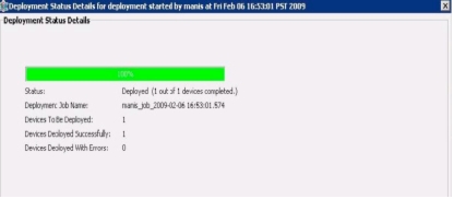
From the File menu select "submit and deploy", select the GM device you want to deploy (demo-gm2) and press the Deploy button.
3.8 Verify GM Configuration Deployment Status
Verify the GM deployment status. You should not see any error. GM should be up and running. Verify "show crypto gdoi" on GM to check GETVPN encryption is enabled. Your GM will receive multicast rekeys from the KS.
4 Deploying KSs
Once one KS device for a particular platform is created, it can be used for provisioning other KSs with same Platform type. In the example given in this document, Cisco 7200 platform is used.
4.1 Prepare New Device for Deployment as KS
Before pushing KS configuration to new device that needs to be deployed as KS, the device should have network connectivity and user credentials. Here is the configuration of demo-ks2 router before deploying configuration from CSM. Minimum configuration includes the following: IP address, routes, hostname, domain name, and user credentials. Following is the minimum configuration is required to push the configuration from CSM:
service password-encryption
!
hostname demo-ks2
!
enable secret 5 $1$Sc9M$a3JvpcoxdtRCXoI/7JUuV.
!
username demo password lab
!
interface GigabitEthernet0/1
description Connected to demo-pe1
ip address 10.5.110.26 255.255.255.252
ip pim sparse-mode
duplex auto
speed auto
!
router eigrp 44
network 10.5.110.24 0.0.0.3
no auto-summary
!
line con 0
exec-timeout 0 0
stopbits 1
line aux 0
stopbits 1
line vty 0 4
password 7 011F0706
login
!
4.2 Connect New Device to Network with IP Address
Configure the new device with IP address so that configuration can be pushed from CSM. Very minimum configuration is required. Complete running configuration for this step is given in section 4.1.
4.3 Clone Device to Deploy new KS
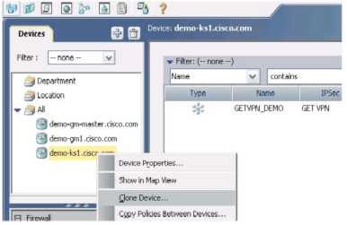
Select the master KS device "demo-ks1.cisco.com", right click on it and select "clone device" as follows:
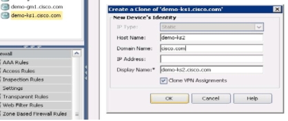
Enter new KS Identity as follows: IP address need to be entered if host name is not published with DNS. After entering required values, click OK.
4.4 Edit Required Values for New KS
Select demo-ks2 device.
4.4.1 Change Host Name
Select Platform, Device Admin and Hostname. Enter hostname as demo-ks2.
4.4.2 Change Interface IP Addresses
Select Interfaces menu and select Interfaces sub-menu under that. Change IP value for demo-ks2 interfaces as follows: Select each interface and change the IP address.
4.4.3 Change Routing Values
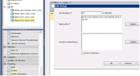
Select Routing and EIGRP menu and edit the routing values for demo-ks2 device as follows:
Select File menu and click "submit".
4.5 Adding New KS to the GETVPN Topology
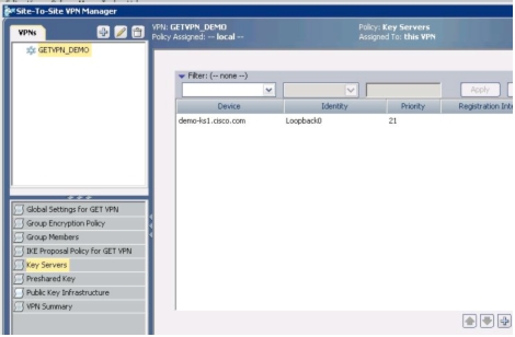
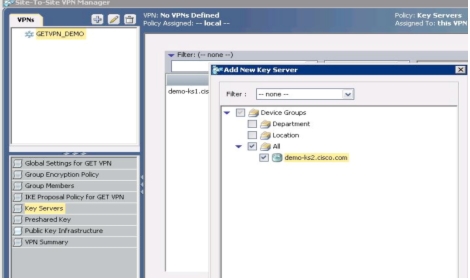
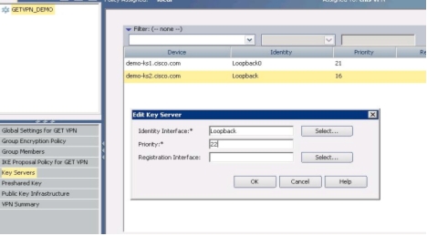
Select "Site-To-Site VPN Manager" icon at the top and select "Key Servers" menu and press "+" button as follows:
Add new KS by selecting demo-ks2.cisco.com and press OK.
Change the redundancy priority of demo-ks2 to 22 as follows:
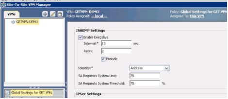
Select Global Settings for GET VPN menu, in ISAKMP Settings select Enable Keepalive, set Interval to 15 secs and Retry to 2 secs. Select Periodic.
Press Save button. Select File menu and click "submit".
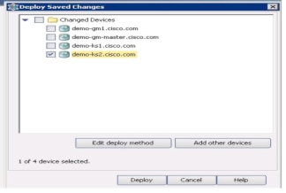
4.6 Deploy new KS by Pushing Configuration from CSM
From the File menu select "submit and deploy", select the KS device you want to deploy as follows and press the Deploy button:
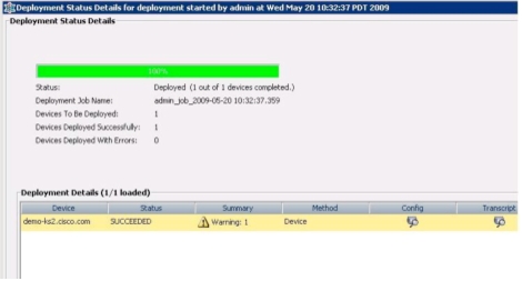
4.7 Verify KS Configuration Deployment Status
Verify the demo-ks2 KS deployment status. You should not see any error. New co-op KS should be up and running.
5 Reference Configuration
Complete configuration of devices used in this document is listed below.
5.1 Configuration of demo-gm1
service timestamps debug datetime localtime show-timezone
service timestamps log datetime localtime show-timezone
service password-encryption
!
hostname demo-gm1
!
boot-start-marker
boot system flash:c2800nm-adventerprisek9-mz.124-22.T
The following list describes acronyms and definitions for terms used throughout this document:
GETVPN
Group Encrypted Transport. A scalable VPN using group technology.
CSM
Cisco Security Manager
GDOI
Group Domain of Interpretation, RFC 3547. A group key management system that is complimentary to IKE.
IKE
Internet Key Exchange, RFC 2409. A pair-wise key management system used to negotiation IPsec tunnels.
IPsec
IP Protocol Security, RFC 2401. The common name for a set of protocols that protect IP packets.
ISAKMP
Internet Security Association and Key Management Protocol, RFC 2408. ISAKMP defines payloads for exchanging key generation and authentication data.
SA
Security Association. SAs contain all the information required for execution of various network security services, such as the IP layer services (such as header authentication and payload encapsulation), transport or application layer services, or self-protection of negotiation traffic.
GM
Group Member
KS
Key Server
PPP
Point-to-Point Protocol
PPPoE
PPP over Ethernet
LNS
Layer 2 Network Server
LAC
Layer 2 Access Concentrator
L2TP
Layer 2 Tunneling Protocol
For more information about the Cisco GETVPN, visit http://getvpn.cisco.com/ or contact your local account representative.