Cisco Clean Access (NAC Appliance) is an easily deployed Network Admission Control (NAC) product that allows network administrators to authenticate, authorize, evaluate, and remediate wired, wireless, and remote users and their machines prior to allowing users onto the network. The solution identifies whether machines are compliant with security policies and repairs vulnerabilities before permitting access to the network. Cisco Clean Access is available in two modes: as either an in-band or out-of-band solution. This white paper explores when and how each mode is appropriate, depending on individual network characteristics and customer preferences.
CISCO CLEAN ACCESS OVERVIEW
• Cisco Clean Access Server-This is an in-band or out-of-band device that acts as the first challenge for any end user trying to access the network. The Cisco Clean Access Server challenges the end user with a login page or requires the download of a Cisco Clean Access Agent before permitting access to the network.
• Cisco Clean Access Manager-This server manages Cisco Clean Access servers remotely, globally, or individually and enables administrators to establish user roles, device checks, and remediation requirements. It also acts as the authentication proxy to the authentication servers that reside on the back end.
• Cisco Clean Access Agent-This is an optional client-side component of the Cisco Clean Access system. It is a read-only client that delivers device-based registry scans on unmanaged environments. It is downloadable and provisioned over the Internet; in fact, customers that use the Cisco Clean Access Agent often make it a required download before network access is granted.
IN-BAND OR OUT-OF-BAND?
Table 1. Comparing In-Band and Out-of-Band Modes
IN-BAND IN-DEPTH
• Shared media ports
• Bandwidth throttling by role required
• Wireless access points
• Voice over IP (VoIP) phones
• Network infrastructure built with products other than Cisco products
Cisco Clean Access In-Band Process Flow: How It Works
Figure 1. Laptop Attempts to Access the Internal Network
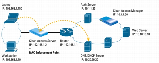
1. When the laptop first accesses the network, the Cisco Clean Access Server determines that the computer's MAC address is not in the list of certified devices, and that laptop is placed into an unauthenticated role. While in this role, only User Datagram Protocol (UDP) Port 53 (Domain Name System [DNS]) and Dynamic Host Control Protocol (DHCP) traffic (via DHCP and VLAN passthrough) is allowed.
2. The laptop gets an IP address from the DHCP server, but cannot get past the Clean Access Server acting as an IP filter.
3. The laptop user opens a browser and is redirected to an SSL-based Web login page where she enters her credentials, which in turn map her into the "employee" role.
4. As an "employee," she is asked to download the Clean Access Agent.
5. The Clean Access Agent performs the posture assessment and forwards the results to the Clean Access Server to make the network admissions decision.
Figure 2. Laptop Goes Through Posture Assessment
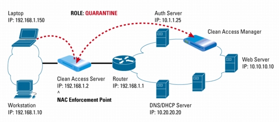
6. The Clean Access Server forwards the report to the Clean Access Manager, which determines that the laptop is not in compliance. The manager instructs the server to put the laptop into the "quarantine" role, which can be as small as a /30 subnet.
7. The Clean Access Manager then sends the remediation steps to the Clean Access Agent.
Figure 3. Clean Access Manager Sends Remediation Instructions to the Clean Access Agent on the Laptop
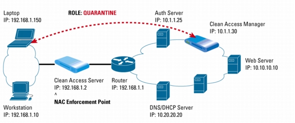
8. A clock displays the time remaining in the quarantine role for the laptop user while the Clean Access Agent guides the user step-by-step through remediation. Patches can be downloaded either from an internal or external update sites (such as http://windowsupdate.microsoft.com) or from the Clean Access Manager itself.
9. After the remediation process, the Clean Access Agent informs the Clean Access Server that the laptop is now compliant.
Figure 4. Once Compliant, Laptop's MAC Address is Added to List of Certified Devices and Access is Granted
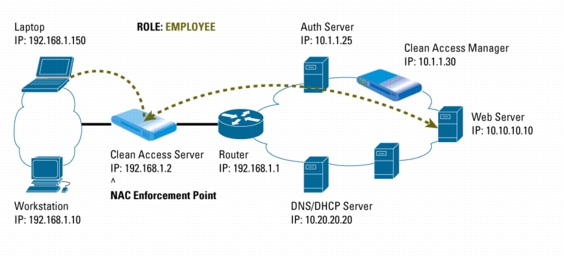
10. The Clean Access Server then adds the MAC address of the laptop onto the certified devices list and assigns it to the employee role, which enables the laptop to complete its access to the internal Web server.
OUT-OF-BAND IN-DEPTH
Cisco Clean Access Out-of-Band Process Flow: How It Works
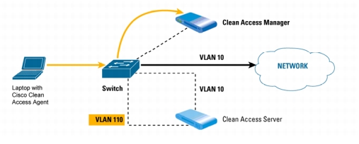
1. When a device first accesses the network, the switch sends the MAC address of the device via SNMP-based notification to the Cisco Clean Access Manager.
Figure 5. Laptop Attempts Access to Network, Switch Sends MAC Address to the Clean Access Manager
2. The Clean Access Manager verifies whether the device is on the out-of-band online list or certified devices list.
3. If the device does not appear on either list, the Clean Access Manager instructs the switch to assign the port the device is on to the authentication or quarantine VLAN. A DHCP address is assigned as DHCP/DNS traffic traverses the Clean Access Server using VLAN mapping.
Figure 6. If Laptop is Not on the Out-Of-Band Online List or Certified Devices List, the Switch Assigns the Device to a Quarantine VLAN
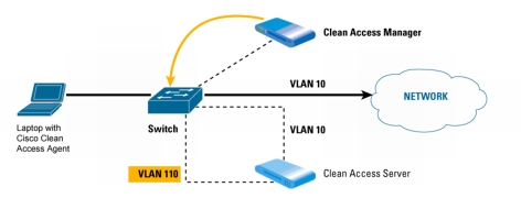
Figure 7. While on the Quarantine VLAN, Laptop Undergoes Posture Assessment
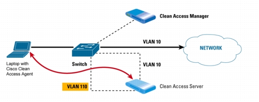
4. The Clean Access Server is on the same authentication VLAN (110) as the device. While in this VLAN, the device is challenged for its credentials to determine the role of its user. If the Clean Access Agent is enforced, it receives compliance checks from the Clean Access Server based on the requirements of that role.
5. The Clean Access Agent guides the user through a step-by-step remediation process; the user is allowed access to remediation sites enforced by the Clean Access Server.
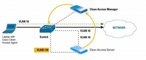
6. Once remediation is completed, the Clean Access Server informs the Clean Access Manager that the device is now certified.
7. The Clean Access Manager then instructs the switch to put the device's port onto the access VLAN (10) based on port mapping or the role assignment. The device is now allowed access to the network.
Figure 8. After Successful Remediation, the Clean Access Manager Instructs the Switch to Move the Laptop to the "Trusted" VLAN
Summary of Differences
Table 2. In-Band and Out-of-Band Deployment Environments
FOR MORE INFORMATION