The Cisco® Enhanced Digital Return (EDR) 85 System expands the functionality of Cisco GS7000 and Cisco GainMaker® Nodes by increasing the performance, reach, and efficiency of the reverse path transmissions.
The Cisco EDR 85 System includes EDR Transmitter modules that install in GainMaker and GS7000 Nodes, and companion Cisco Prisma® high-density (HD) EDR PRX85 Receiver modules that install in a Prisma II or Prisma II XD chassis at the headend or hub. The transmitter and receiver use Small Form Factor Pluggable (SFP) optical pluggable modules (OPMs) for enhanced flexibility. The Cisco EDR 85 System operates over the 5-85 MHz range and supports all standard reverse frequency bandwidths at 40, 42, 55, 65, and 85 MHz.
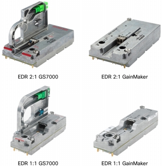
At the transmit (node) end of the system, reverse-path RF input signals from each node port are routed to an EDR 2:1 or EDR 1:1Transmitter module in the housing lid. The transmitter module converts each signal to a baseband digital data stream and combines the signals into a serial data stream using time-division multiplexing (TDM). The baseband data stream is then converted to an optical signal for transmission to the headend or hub. The double-wide (2:1) transmitter modules occupy two transmitter slots and the 1:1 modules occupy one slot. The EDR 2:1 Transmitter is available for the GS7000 and GainMaker (4-Port or Reverse Segmentable) platforms (Figure 1). The EDR 1:1 Transmitter is available for the GS7000 and all GainMaker Node platforms (Figure 1). The transmitter OPMs are available in either Coarse Wavelength Division Multiplexing (CWDM) 1270-1610 nm wavelengths or Dense Wavelength Division Multiplexing (DWDM) ITU channels (17-61 nm).
Figure 1. Cisco EDR Transmitter Modules
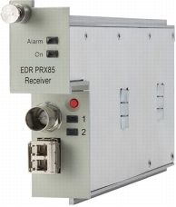
At the receive end, typically in a large hub or headend, the EDR Receiver module receives the optical signal and performs the conversion back to the baseband data stream. The resulting data streams are converted back to analog reverse path signals for routing to termination equipment. The EDR Receiver module is available in the High Density form factor. The receiver OPMs are available in Standard Range (SR) and Extended Range (XR) configurations. Both configurations feature a dual LC/PC optical input connector that feeds two independent reverse optical receivers, each with its own RF output port.
A single EDR Receiver module (Figure 2) occupies one slot in a Cisco Prisma II XD chassis. Two EDR HD receiver modules can be vertically stacked in an associated Prisma II Host Module that occupies a single-wide slot in the Prisma II standard chassis. Up to 26 HD modules can operate in a standard 6 rack unit (6RU) chassis (the 56-connector version of the chassis is required to make use of both receivers in one chassis slot). Up to 16 HD modules can operate in the Prisma II XD chassis. The ability to mix EDR Receiver modules with other Prisma II HD modules in the same chassis greatly enhances the flexibility of the platform.
Figure 2. Cisco EDR Receiver Module
Features
• High-performance digital reverse technology:
– 12-bit encoding that enables transmission of analog video in the reverse band
– High-order digital modulation signals (for example,16 quadrature amplitude modulation [QAM], 64 QAM, and 256 QAM)
• Multiple operating modes in the EDR receiver that support the EDR transmitter and the older integrated 2:1 bdr node transmitter
• Optical pluggable modules that provide flexible inventory management
• Long-reach transmission capabilities that eliminate the need for optical amplifiers, reducing cost and space requirements
• Capability to send 90 individual 5-85 MHz reverse signals over a single fiber:
– Use of 2:1 multiplexing to reduce fiber usage
– Compatibility with Cisco's 45-wavelength DWDM system
• Support for independent balancing of reverse traffic at EDR receiver RF ports
• Simplified setup that reduces installation time and expertise requirements
• Distance- and temperature-independent link performance that simplifies engineering and maintenance requirements
• Space-saving, high-density deployment in Prisma II or Prisma II XD chassis to increase deployment cost-efficiency
• Optional monitoring of node (GS7000) and transmitter (GS7000 and GainMaker) parameters available at the receiver
Block Diagrams
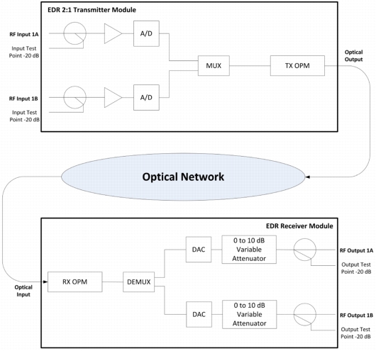
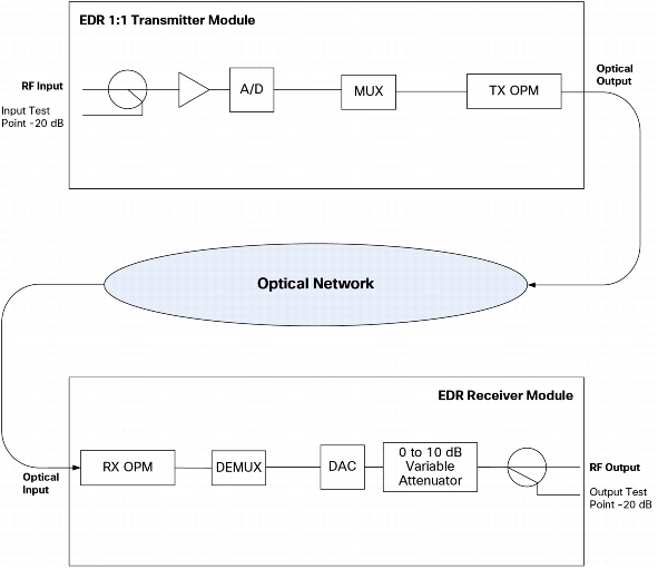
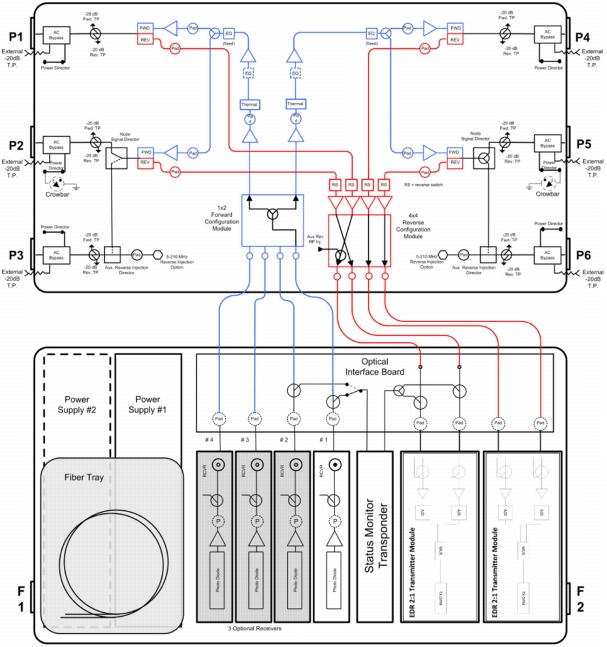
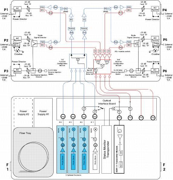
Figures 3 and 4 provide block diagrams of the EDR systems for 2:1 and 1:1 transmission.
Figure 3. Cisco EDR 85 System with 2:1 Transmitter
Figure 4. Cisco EDR 85 System with 1:1 Transmitter
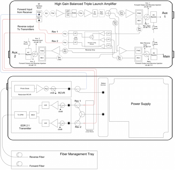
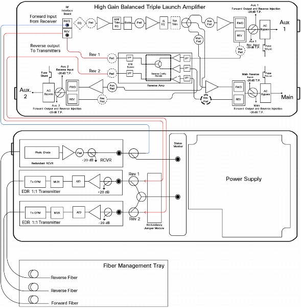
Figures 5 and 6 show block diagrams for EDR 2:1 and 1:1Transmitters in a GS7000 node. Figures 7 and 8 provide block diagrams for EDR 2:1 and 1:1 transmitters in a GainMaker node.
Figure 7. Cisco 2:1 EDR Transmitter Module in a Cisco GainMaker Node
Figure 8. Cisco 1:1 EDR Transmitter Module in a Cisco GainMaker Node
Product Specifications
Table 1 lists specifications for the EDR 85 Transmitter modules. Table 2 gives specifications for the EDR Receiver module. Table 3 lists RF link performance specifications.
Table 1. Cisco EDR 85 Transmitter Modules
Specification
Units
Value
RF input level
dBmV/Hz
See Table 3
RF input test point
dB
-20 (± 1 dB)
Test point return loss (minimum)
dB
18
Power consumption (maximum)
W
< 4
Operating temperature range, node ambient
°C
°F
-40 to +60
-40 to +131
Physical dimensions, GS1185 Module
(L x W x H)
in.
cm
5.75 x 1.45 x 3.90
14.50 x 3.68 x 9.91
Physical dimensions, GM1185 Module
(L x W x H)
in.
cm
5.75 x 1.45 x 1.40
14.50 x 3.68 x 3.56
Weight, GS1185 module
lb
kg
0.8
0.36
Weight, GM1185 module
lb
kg
0.5
0.23
Physical Dimensions, GS2185 Module
(L x W x H)
in.
cm
5.75 x 2.95 x 3.90
14.50 x 7.49 x 9.91
Physical Dimensions, GM2185 Module
(L x W x H)
in.
cm
5.75 x 2.95 x 1.40
14.50 x 7.49 x 3.56
Weight, GS2185 Module
Lb
kg
1.5
0.68
Weight, GM2185 Module
Lb
kg
1.0
0.45
Table 2. Cisco EDR 85 PRX85 Receiver Module
Specification
Units
Value
Notes
RF output level
dBmV/Hz
See Table 3
RF output return loss (minimum)
dB
18
Output RF variable gain control range
dB
0 to -10 (0.5 dB increments)
Power consumption (maximum)
W
< 9
RF output test point
dB
-20 (± 1 dB)
RF output test point return loss
dB
18
Operating temperature range
°C
°F
0 to 50
32 to 122
1
Physical dimensions (D x W x H)
in.
cm
8.8 x 1.0 x 3.5
22.35 x 2.54 x 8.89
Weight
lb
kg
0.9
0.4
Note:
1. Recommended for use only in noncondensing environments.
Table 3. RF Link Performance
General
Units
Value
Notes
Bandpass
MHz
5 - 85
Full-scale single carrier wave (CW) carrier amplitude
dBmV
33
1, 2
Link gain
dB
15.5 (± 1.0 dB)
3, 4, 5
Response flatness
dB
± 0.5
Notes:
1. With respect to the input port on the EDR Transmitter module.
2. A CW carrier of this amplitude applied to the RF input will exercise the full-scale range of the A/D converter. Full scale is analogous to 100% OMI for analog lasers.
3. Variable gain control on EDR Receiver module set to 0 dB.
4. Add link gain (dB) to EDR Transmitter module RF input level to determine EDR Receiver module RF output level.
5. At low and high temperature extremes.
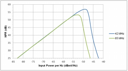
Tables 4 and 5 provide group delay and optical link specifications. Figure 9 shows noise power ratio (NPR) performance.
Table 4. Group Delay, 1-MHz Bandwidth
Frequency (MHz)
Units
Value
Notes
5-10
ns
£ 2.0
11-85
ns
£ 1.5
Table 5. Optical Link Characteristics
General
Units
Value
Notes
Link budget
dB
21 (SR Rx)
28 (XR Rx)
Optical wavelength
nm
1270 - 1610 (CWDM)
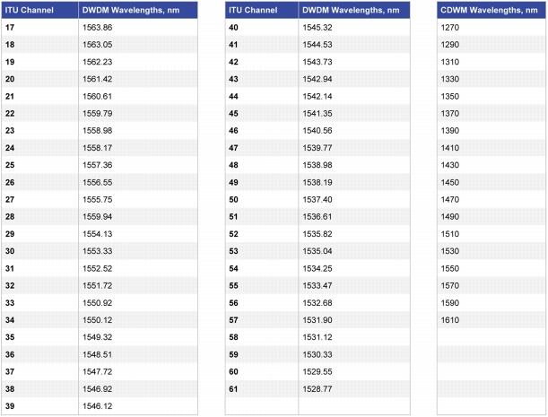
1563.86 - 1528.77 (DWDM)
1
Optical output power (modulated)
dBm
3 minimum (CWDM)
3 minimum (DWDM)
1
Optical input power (SR module)
dBm
-8 to -18
2
Optical Input power (XR module)
dBm
-8 to -25
2
Optical interface
LC/PC Connector
Notes:
1. Applies to Transmitter module only.
2. Applies to Receiver module only.
Figure 9. Cisco EDR 85 Noise Power Ratio Performance: Input Power per Hz
Notes:
1. Input power is specified with respect to the input port of the EDR Transmitter module.
2. Variable gain control on the EDR Receiver module set to 0 dB.
3. Unless otherwise stated, all link performance specifications shown reflect minimum performance over the specified operating temperature range of the GS7000 and relevant GainMaker Nodes. The EDR Receiver module specifications are for the optical link only, measured from the input to the GS7000 or GainMaker Node EDR Transmitter module to the output of the receiver module. Refer to the relevant node data sheets for other node-related specifications.
Ordering Information
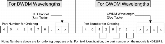
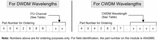
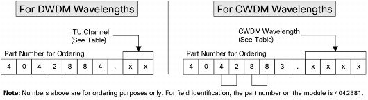
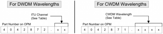
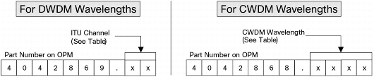
Figure 10 provides ordering matrixes for the Cisco EDR 85 System components. Tables 7, 8, and 9 list part numbers for Cisco Prisma EDR required equipment, additional required equipment, and accessories.
Figure 10. Ordering Matrixes for Cisco EDR 85 System
EDR GS2185 GS7000 2:1 Transmitters with OPM Order Matrix
EDR GS2185 GS7000 1:1 Transmitters with OPM Order Matrix
EDR GM2185 GainMaker 2:1 Transmitters with OPM Order Matrix
EDR GM2185 GainMaker 1:1 Transmitters with OPM Order Matrix
Transmitter 2:1 Optical Pluggable Module (OPM) Order Matrix
Transmitter 1:1 Optical Pluggable Module (OPM) Order Matrix
Table 6. DWDM and CWDM Wavelengths
Table 7. Cisco Prisma EDR Required Equipment
Description
Part Number for Ordering
Part Number on Module
Part Number on OPM
EDR GS2185 Tx module
4042877
4042904
N/A
EDR GS1185 Tx module
4042873
4042188
N/A
EDR GM2185 Tx module
4042885
4041274
N/A
EDR GM1185 Tx module
4042881
4042187
N/A
EDR PRX85 Prisma HD Rx module
4041277
4041278
N/A
EDR PRX85 Prisma HD Rx w/SR OPM
4042748
4041278
4044008
EDR PRX85 Prisma HD Rx w/XR OPM
4042749
4041278
4044009
EDR Rx OPM SR
4042750
N/A
4044008
EDR Rx OPM XR
4042751
N/A
4044009
Table 8. Additional Required Equipment
Description
Part Number
GS7000 Optical Node
Refer to GS7000 data sheets
GainMaker Optical Nodes
Refer to GainMaker Node data sheets
Table 9. Accessories
Description
Part Number for Ordering
Part Number on Unit
EDR Tx Fiber Jumper GM and GS7K
4044313
4042940
Local Control Module (LCM) for EDR Interface
4044102
4044101
Service and Support
Using the Cisco Lifecycle Services approach, Cisco and its partners provide a broad portfolio of end-to-end services and support that can help increase your network's business value and return on investment. This approach defines the minimum set of activities needed by technology and by network complexity to help you successfully deploy and operate Cisco technologies and optimize their performance throughout the lifecycle of your network.