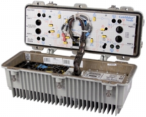
The Cisco GainMaker® 1 GHz High Output 4-Port Node is designed to serve the cornerstone of today's emerging fiber deep network architectures. The node combines the proven Cisco® technologies of both the Cisco GainMaker 1 GHz RF Amplifier and Cisco Prisma® optical components. Featuring four high-level RF output ports and a segmentable reverse path, it is an ideal platform for delivering video (digital and analog) as well as high-speed data services over advanced hybrid fiber-coaxial (HFC) networks.
Reverse traffic can be segmented and routed to distributed feedback (DFB), coarse wavelength-division multiplexing (CWDM), dense wavelength-division multiplexing (DWDM), or Enhanced Digital Reverse (EDR) transmitters. The Cisco GainMaker 1 GHz High Output 4-Port Node (Figure 1) is also available with an optional DOCSIS status-monitoring transponder for use with all HMS-compliant monitoring and control element management systems. Onboard temperature, RF switch position (wink switch), power supply condition, as well as other features and parameters can be monitored through this module.
Installation of the Cisco GainMaker 1 GHz High Output 4-Port Node is quick and easy. The fiber receiver is delivered with preconnectorized fiber terminations. The optional preconnectorized cable stub is the ideal method for connecting the Cisco GainMaker 1 GHz Node to the fiber network. The Cisco GainMaker 1 GHz Node includes a 4-fiber handling tray for these cables.
Figure 1. Cisco GainMaker High Output 4-Port Node with 85/105 MHz Split
Features
• Uses plug-in accessories common to all Cisco GainMaker nodes and GS7000 products (i.e. attenuator pads, equalizers, diplexers and crowbar)
• Reverse segmentation with two analog DFB, CWDM, or DWDM reverse transmitters
• Reverse segmentation with two 1:1 Enhanced Digital Return (EDR) transmitters
• Supports one 2:1 EDR transmitter (occupies two transmitter slots)
• Interstage Equalizer (ISEQ) provides 14.5 dB of Linear tilt
• Amplifier cover provides access to RF Test Points
• Two optical transmitter positions in the lid
• One optical receiver position in the lid
• Optional DOCSIS Status Monitoring plug-in Transponder
• Optional reverse redundancy option; two reverse transmitters (one in "hot standby") available for the non-segmented node case
• Fiber management tray provides easy access to fiber connections and folds back to provide access to optical transmitter and receivers
• Power supply mounted in housing lid for efficient thermal dissipation (60 and 90 volt AC powering capability)
• Reverse input pad and RF test point for each reverse input port on Cisco GainMaker launch amplifier allow optimum reverse path design and alignment
• Optional Dual Redundant Receiver provides ability to switch to redundant optical power in case of fiber cut
• QAM and analog Pilot AGC available (optional)
• AGC has Thermal backup, which eliminates disruptive RF output variation in the event of pilot loss
• Local test points and LED indicators on optical receivers, transmitters, and optical interface board simplify installation and maintenance
• Integrated 3-state reverse switch (on/off/-6 dB) allows each reverse input to be isolated for noise and ingress troubleshooting (status monitoring required)
• Surge resistant circuitry ensures gain stage protection without fuses or other nuisance failure causing devices
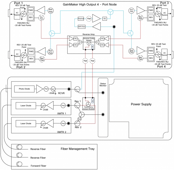
Block Diagrams
Figures 2 through 5 provide block diagrams of configuration options for the Cisco GainMaker High Output 4-Port Node.
Figure 2. Combined Reverse Path with Redundant Transmitter Block Diagram
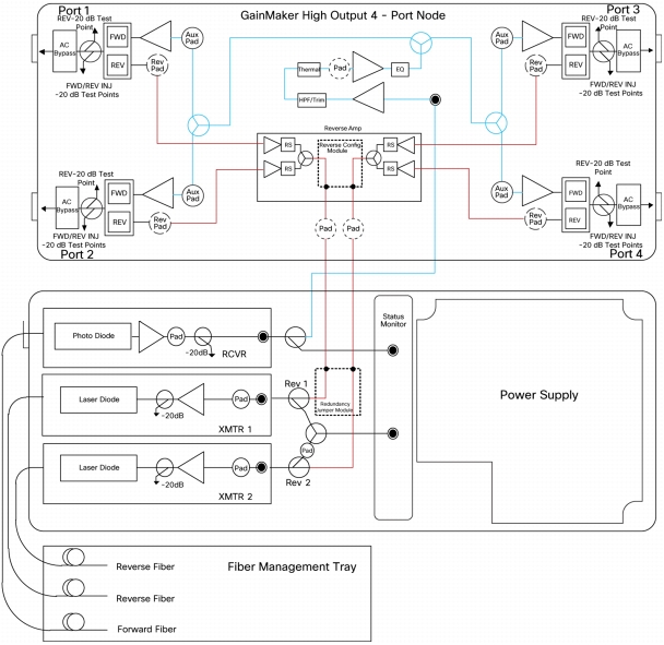
Figure 3. Segmented Reverse Path Block Diagram
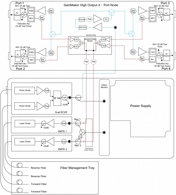
Figure 4. Dual Redundant Receiver Block Diagram
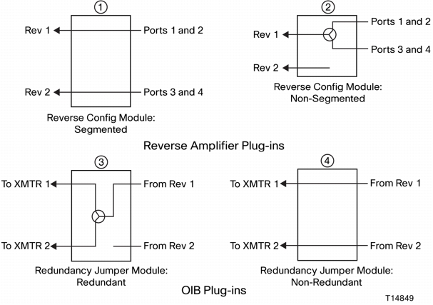
Figure 5. Configuration Module Block Diagram
Table 1 lists all possible reverse amplifier plug-in and Optical Interface Board (OIB) plug-in combinations. Each circled number references the plug-ins shown in Figure 5.
Table 1. Reverse Amplifier and Optical Interface Board Plug-in Combinations
Transmitters
Reverse Amplifier Plug-in
OIB Plug-in
Segmented XMTRS (nonredundant)
①
④
Redundant XMTR (nonsegmented)
②
③
Nonsegmented and nonredundant
②
④
Optical Specifications
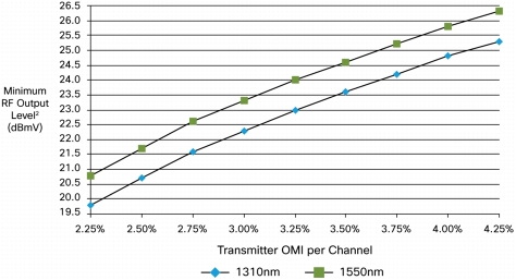
Table 2 lists optical section specifications for the forward receiver module, and Figure 6 compares receiver RF output levels with the transmitter Optical Modulation Index (OMI). The notes following Figure 6 also apply to Table 2.
Table 2. Optical Section
Optical Section: Forward Receiver Module
Units
GainMaker Standard RX
Notes
Wavelength
nm
1310 and 1550
Optical input range
mW
dBm
0.5-1.6
-3 -+2
Pass band
MHz
52-1002
Frequency response
dB
± 0.75
1
Tilt (±1.0 dB)
dB
0
Optical input test point (±10%)
VDC
1V per mW
RF output level at 0 dBm optical input
dBmV
Refer to Figure 6
2
RF output test point (±1.0 dB)
dB
-20
Figure 6. Receiver RF Output Level and Transmitter OMI
Notes:
1. For forward receiver module only. Does not include frequency response contributions from forward optical transmitter
2. Minimum receiver RF output level for the stated transmitter percent OMI per channel, with receiver optical input power of 0 dBm. To determine RF output levels at other optical input power levels, add (or subtract) 2 dB in RF level for each 1 dB increase (or decrease) in receiver optical input power
For reverse optical transmitter and link performance, see the "Analog Reverse Optical Transmitters for Model 6940/6944 and GainMaker Optoelectronic Stations" data sheet, part number 750874.
Other Product Specifications
Tables 3 through 9 provide additional specifications for the Cisco GainMaker GainMaker High Output 4-Port Node with 85/105 MHz Split.
Table 3. RF Section Specifications
General Station Performance
Units
Forward
Reverse
Notes
Pass band
MHz
105-1002
5-85
Return loss
dB
16
16
Hum modulation at 12A
dB
70 (105-870 MHz)
60 (870-1002 MHz)
60 (5-10 MHz)
70 (11-85 MHz)
Hum modulation at 15A
dB
65 (105-870 MHz)
60 (870-1002 MHz)
60 (5-10 MHz)
65 (11-85 MHz)
Test points (±0.5 dB)
dB
-20
-20
Table 4. Launch Amplifier Performance: Forward
Launch Amplifier Performance: Forward
Units
GainMaker 4-Port
Notes
Operational gain (minimum)
dB
41
Frequency response
dB
±0.5
Internal tilt (±1 dB)
dB
13.8
1, 2
Noise figure at: 105 MHz
1002 MHz
dB
8.5
8.0
Reference output levels at: 1002 MHz
870 MHz
750 MHz
650 MHz
550 MHz
105 MHz
dBmV
56.0
54.0
52.2
50.5
49.0
41.5
Reference output tilt (55-1002 MHz)
dB
13.7
1, 3
78 NTSC Channels (CW) with Digital
5
Composite triple beat
dB
65
4
Cross modulation
dB
59
4, 6
Composite second order (high side)
dB
64
4
Composite intermodulation noise (CIN)
dB
57
4, 7
Notes:
1. Reference output tilt and internal tilt are both "linear" tilts
2. Forward internal tilt specified is primarily due to an on-board equalizer and a factory configured linear interstage equalizer (ISEQ)
3. The forward reference output tilt specified is achieved through field installation of appropriate input equalizer, in conjunction with the internal tilt of the launch amplifier and the tilt associated with the optical link (transmitter and receiver combination)
4. Station performance can be determined by combining optic performance and launch amplifier performance. Stated distortion performance is for launch amplifier section operated at reference output levels and tilt
5. "Digital" refers to 550 to 1002 MHz loading with QAM carriers at -6 dB relative to analog video carrier levels
6. X-mod (at 15.75 kHz) specified using 100% synchronous modulation and frequency selective measurement device
7. Composite Intermodulation Noise (CIN) is a broadband noise-like distortion product associated with QAM loading
Table 5. Launch Amplifier Performance - Reverse
Reverse Station Performance
Units
Reverse
Notes
Amplifier type
-
GaAs FET
Operational gain (minimum)
dB
-2
1, 2
Frequency response
dB
± 0.5
Internal tilt (±1 dB)
dB
0
Path to path isolation
dB
50
Noise figure
dB
13.5
2
Notes:
1. Reverse operational gain is measured from the reverse RF input port to the RF input to the reverse transmitter and includes optical interface board losses.
2. Reverse gain and noise figure for launch amplifier with 0 dB reverse input pad and 0 dB output pad.
Table 6. RF Delay Specifications
Station Delay Characteristics
Forward (Chrominance to Luminance Delay)
Reverse (Group Delay in 1.5 MHz BW)
Frequency (MHz)
Delay (nS)
Frequency (MHz)
Delay (nS)
109.25 - 112.83
8
5.0 - 6.5
33
115.25 - 118.83
5
6.5 - 8.0
15
121.25 - 124.83
4
8.0 - 9.5
8
80.5 - 82.0
5
82.0 - 83.5
7
83.5 - 85.0
10
Table 7. Electrical Specifications
Electrical
Units
Value
Notes
Maximum AC through current (continuous)
A
15
Maximum AC through current (surge)
A
25
Component DC Power Consumption (Typical)
at +24 VDC
at +15 VDC
at -6 VDC
1
Launch amplifier
A
2.60
Status monitoring transponder
A
0.15
Standard optical receiver
A
0.25
0.01
0.035
Reverse transmitter: high gain FP
A
0.09
-
0.07
Reverse transmitter: high gain DFB
A
0.11
-
0.09
Power supply DC current rating
A
3.5
0.05
0.35
1
Note:
1. The total DC power consumption of installed components should not exceed the power supply DC current rating.
24 VDC at 3.2A, 15 VDC at 0.01A, and -6 VDC at 0.215A
AC voltage
90
80
70
60
50
40
AC current (A)
1.21
1.26
1.45
1.69
1.97
2.47
AC power (W)
92.31
91.67
90.91
90.49
90.22
90.5
Table 9. Environmental and Mechanical Specifications
Environmental
Units
Value
Operating temperature range
°F and °C
-40 to 140°F (-40 to 60°C)
Relative humidity range
%
5 to 95%
Mechanical
Housing dimensions
(L x H x D)
in. and mm
17.6 in. x 7.5 in. x 7.9 in.
(447 mm x 191 mm x 201 mm)
Weight
(station with 1 RX, 1 TX, and power supply)
lb and kg
22.5 lb (10.2 kg)
Ordering Information
The Cisco GainMaker High Output 4-Port Node with 85/105 MHz Split is available in a wide variety of configurations. The GainMaker Ordering Matrix provides ordering information for configured node stations and launch amplifiers. Tables 10 and 11 contain ordering information for required and optional accessories, and Tables 12 and 13 give information for transmitters and receivers and for related equipment. Please consult with your Account Representative, Customer Service Representative, or Applications Engineer to determine the best configuration for your particular application.
Table 10. Required Accessories
Required Accessories for RF Module
Part Number
Plug-in Pads (attenuators): available in 0.5-dB steps from 0 to 20 dB
• 1 required for interstage (if 0 dB value installed in the node when shipped does not fit the system design)
• 6 required for reverse (4 input, 2 output)
589693 (0 dB) sequentially through 589734 (20.5 dB)
Plug-in Forward Linear Equalizer: available in 1.5-dB steps from 0 to 30 dB at 1002 MHz
• 1 required for forward input
See Table 10
Required Accessories for Optical Components
Part Number
Plug-in Pads (attenuators): available in 0.5-dB steps from 0 to 20.5 dB
• 1 each required for transmitter and receiver(s)
279500 (0 dB) sequentially through 279513 (13 dB) in 1-dB steps
504151 (14 dB) sequentially through 504157 (20 dB) in 1-dB steps
565231 (0.5 dB) sequentially through 565251 (20.5 dB) in 1-dB steps
Note: Configured nodes ship without reverse input pads and without forward input pads or equalizer. All other accessories are shipped from the factory. Forward launch amplifier attenuator pads, interstage equalizer and system trim are shipped with every configured node.
Table 11. Optional Accessories
Reverse Amplifier Segmentation Module
Part Number
Reverse Configuration Module: Nonsegmented (box of 5)
4018565
Reverse Configuration Module: Segmented (box of 5)
4018564
OIB Redundancy Module
Part Number
Redundancy Jumper Module Plug-in: Redundant (box of 5)
4018565
Redundancy Jumper Module Plug-in: Nonredundant (combined) (box of 5)
4018564
Launch Amplifier Module
Part Number
on Module
Part Number
for Ordering
GainMaker High Output 4-Port Launch Amplifier 85/105 MHz (GM4P-LA-85105)