Compact nodes can be configured with a variety of optical reverse transmitters to provide flexibility for use in multiple applications. The reverse transmitters are plug-in modules that deliver a cost-effective, user-friendly solution for upstream transmission. The Cisco® Compact Reverse Transmitters 9008x are available with Fabry-Perot (FP), distributed feedback (DFB), or Coarse Wavelength Division Multiplexing (CWDM) lasers.
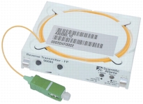
All reverse transmitters feature a built-in microprocessor and pilot tone for easy setup of the reverse path. The pilot tone does not take up any reverse bandwidth, as it is placed at 5 MHz. Placing the pilot tone at 5 MHz also makes the reverse transmitter interoperable with almost all reverse receivers in the marketplace. In the event of no modulation, the pilot tone serves as a quieting tone, which reduces spurious noise and improves overall noise performance with up to 15 dB. All reverse transmitters have increased gain, which allows low reverse input levels at the node. Figure 1 shows the 90080 model.
Figure 1. Cisco Compact Reverse Transmitter 90080
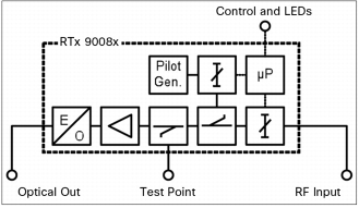
Figure 2 provides a block diagram for the reverse transmitters.
• Designed to operate within the compact platform of optical nodes
• Variable modulation depth (RF drive level) supports superior link optimization
• RF input test point
• 5 MHz pilot tone for easy setup
• Multiple setup and control options:
– Local control through front panel or Cisco Handheld Programmer Terminal 91200
– Advanced element management (status monitoring and control) interface
• Nonvolatile storage of preset operating parameters
• Remote Optical Modulation Index (OMI) setting (when supported by node)
Additional Features Type 90080
• Uncooled high-performance FP lasers
Additional Features Type 90083 and 90086
The 90083 and 90086 reverse transmitters are an integral part of the CWDM transport system enabling each fiber in a hybrid fiber-coaxial (HFC) network to support a 16-fold increase in the number of wavelengths available.
• 90083: 3 dBm, 1310 nm DFB available in 16 CWDM wavelengths
• 90086: 6 dBm, 1550 nm DFB available in 16 CWDM wavelengths
• Uncooled DFB lasers with isolator for exceptional performance and low power consumption
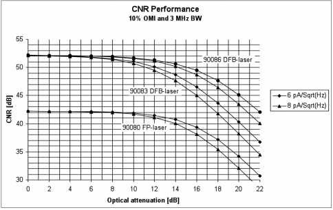
Carrier-to-Noise Ratio Performance
Figure 3 shows carrier-to-noise ratio (CNR) performance data.
Figure 3. CNR Performance
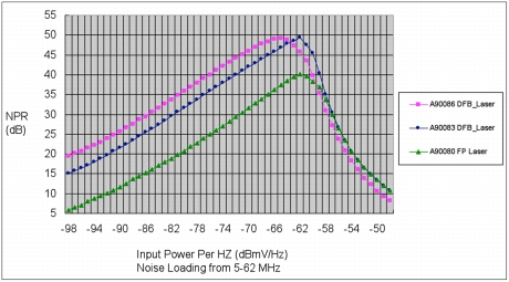
NPR Performance Descriptions
NPR Performance Type 9008x Reverse Transmitter
The test condition shown in Figure 4 is: Cisco Prisma® II Reverse Optical Receiver, 10 dB Optic Link (20 km glass, plus passive loss), node A90090 in default setting, and room temperature.
Figure 4. NPR Performance
Node Correction Factor
An A90090 Node is used in the above NPR tests. For other nodes as listed in Table 1, the X axis, which presents input power per Hertz must move to the left by a correction factor (node with default configuration and test with a reverse jumper).
Table 1. Node Correction Factor
Node
Correction Factor (dB)
A90090/A90093
0
A90201 (preliminary)
0.5
A90100/A90300
1.5
A90200
3.7
A90285/A90286
6.5
A90075/A90275
6.5
Example: Node type A90200 has a correction factor of 3.7 dB. From the NPR curve in Figure 4, a FP laser (A90080) will have the best NPR performance (40dB) at an input of -62dB/Hz. For Node type A90200 the required input power/Hz will need to increase to -58.3 dB/Hz (= -62+ 3.7) to achieve the best NPR performance.
The NPR performance plots contained in this document depict the NPR performance on a reference 10-dB fiber optic link.
With other link losses, the following items vary from that shown on the reference 10 dB link plots.
• NPR dynamic range for a given minimum NPR (C/N) performance
• NPR value for a given transmitter RF input level
To determine an NPR dynamic range for a different link loss, add (or subtract) the correction factor associated with the desired link loss to (or from) the dynamic range shown on the reference 10 dB link NPR plot. Note that the associated increase (or decrease) in dynamic range affects only the left side of the NPR curve (minimum RF input side) since that is the portion of the curve affected by changes to the traditional noise sources associated with optical link.
To determine an NPR value for a different link loss, add (or subtract) the correction factor associated with the desired link loss to (or from) the NPR value shown on the 10 dB link NPR plot for a given RF input level. Again, only the NPR values on the left side of the NPR curve (pre-peak values) are to be adjusted. The NPR values and slope associated with the right side of the NPR curve (post-peak values) are primarily due to laser clipping the high RF input levels, and therefore do not vary appreciably with link loss.
Table 2 lists link loss correction factors.
Table 2. Link Loss Correction Factors
Optical Link Loss (dB)
Fiber Length (km)
Loss Correction Factor (dB)
A90080
A90083
A90086
2
0
6
3.25
N/A
3
5
3.5
1.8
1.5
6
12.5
1
1
1
8
12.5
0.5
0.5
0.9
9
20
0
0
0
10
20
0
0
0
12
20
-1
-1
-1
15
20
-3.5
-3
-1.6
18
20
-8
-7
-4.5
20
20
N/A
-10
-6.5
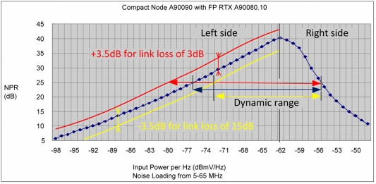
Example: Figure 5 shows how dynamic range (for NPR of 25 dB) of a FP-laser (A90080.10) will be influenced for 3 dB link loss and 15 dB link loss.