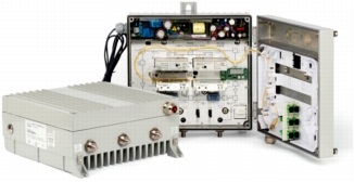
The Cisco® Compact EGC GaN Segmentable Node A90201 with 85-105 MHz Split is designed to meet the growing need for network segmentation. The node provides advanced features and benefits, helps operators reduce operating costs by streamlining node segmentation deployments and configuration, and is well suited for migration toward Fiber to the Curb (FTTC) and Fiber to the Building (FTTB) architectures.
The node makes use of the latest developments in GaN (Gallium Nitride) monolithic microwave integrated circuits (MMICs), bringing excellent RF performance at a lower power consumption (compared to GaAs technology). It can be configured electronically for rapid initial setup or for adjustments that are needed as network requirements shift. All settings can be done without service interruption, an especially important capability in networks that deliver real-time interactive services such as Voice over IP (VoIP) and high-speed data transmission. The node's interface allows easy configuration through a handheld programmer terminal or by connection to a standard PC. This interface allows the settings to be stored and reapplied to streamline configuration.
The node provides flexible options because of its large optical input range and high RF output level. Thus, it can work with a large variety of reverse transmitters to support a variety of applications within the network.
The number of plug-ins has been minimized to help operators keep inventory and costs down. The full-range electronic attenuators and equalizers offer improved versatility and make it possible to achieve the same adjustment range as with conventional plug-ins or potentiometer solutions. A plug-in diplexer filter is used to determine the forward/reverse band split.
To meet future demands for more bandwidth, the node offers an electronic 862-MHz to 1-GHz field-programmable bandwidth extension, and reverse path that can be upgraded to 200 MHz.
The Cisco Compact EGC GaN Segmentable Node A90201 with 85-105 MHz Split can be configured with a Cisco status monitoring transponder (Status Monitoring and Control [SMC], Hybrid Management System [HMS], or DOCSIS) to enable remote monitoring of critical node parameters and remote control of the built-in 3-state reverse switch.
Figure 1. Cisco Compact EGC GaN Segmentable Node A90201 with 85-105 MHz Split
Features
Improved distortion at a lower power consumption with GaN-based output stages
RF output level adjustable over a wide range: 94 to 119 dBµV
Wide optical input: -7 to +2 dBm
Configurable for 1 GHz or 862 MHz operation
Configured by Electronic Gain Control (EGC) technology
Full segmentable in forward path and reverse path
Automatic redundancy switching for forward path
Easy setup and control
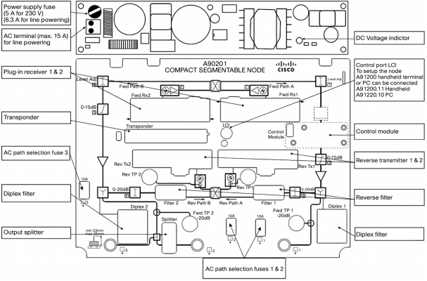
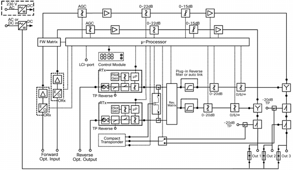
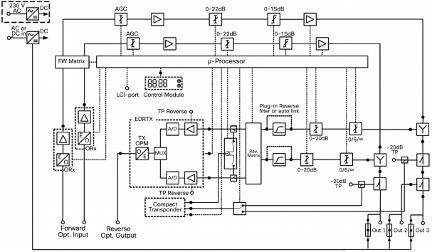
Product Diagrams
Figures 2, 3, and 4 provide an overview and block diagrams for the Cisco Compact EGC GaN Segmentable Node A90201 with 85-105 MHz Split.
Figure 2. Overview
Figure 3. Block Diagram (with RTX)
Figure 4. Block Diagram (with EDR TX)
Product Specifications
This section provides product specifications. Table 1 lists optical specifications, Tables 2 and 3 give forward and reverse RF specifications, and Table 4 lists station powering specifications. Table 5 provides environmental, mechanical, compliance, and safety specifications.
Optical Specifications
Item
Value
Optical
Optical wavelength
1200-1600 nm
Optical input level
-7 to +2 dBm
AGC accuracy
≤ ±0.5 dB
Equivalent Input Noise (EIN) current
7 pA/at 86-862 MHz
8 pA/at 86-1006 MHz
Table 2. Forward RF Specifications
Item
Value
Forward RF1
Frequency range
Selectable 86-862 MHz or 86-1006 MHz
Output level range
94-119 dBµV at 3.25% OMI per ch
Responsivity
67.25 ±0.5 dB A/W at full gain, 1310 nm
Flatness
≤ ±0.75 dB at 86-862 MHz
≤ ±1.0 dB at 86-1006 MHz
Interstage tilt
0-15 dB, 0.5 dB step
Path to path isolation
≥ +60 dB at 86-862 MHz
≥ +55 dB at 862-1006 MHz
Output return loss
≥ 18 dB at 5-65 MHz, reduce 1.5 dB per octave
Output test point return loss
≥ 20 dB at 5-65 MHz, reduce 1.5 dB per octave
Output test point
-20 ±0.5 dB at 86-862 MHz,
-20 ±0.75 dB at 86-1006 MHz
Distortion2
• CTB
• CSO
≤ -60 dB
≤ -60 dB
Distortion3
(with power saving on)
CTB
CSO
≤ -60 dB
≤ -60 dB
Hum modulation4
≤ -65 dB at 86-1006 MHz
Thermal stability
≤ ±1.0 dB
Redundant receiver switchover time
≤ 25 ms
Number of optical inputs
2
Number of RF output ports
2 active outputs + 1 additional output with plug-in output splitter
Group delay
Df = 1 MHz
Df = 4.43 MHz
≤ 3 nsec
at 86-94 MHz
≤ 2 nsec
at 95-112 MHz
≤ 2 nsec
at 112.25-116.68 MHz
≤ 1 nsec
> 119.25 MHz
Transponder pick-off point5
-33 ±1.5 dB
Notes:
1. Unless otherwise specified, all forward band specifications are tested with a 65/86 diplexer module installed.
2. CENELEC 42 ch, 3.25% OMI, 9 dB tilt, and output level 116 dBµV.
3. CENELEC 42 ch, 3.25% OMI, 9 dB tilt, and output level 113 dBμV.
4. At 8 Ampere AC current.
5. Relative to the level of the node output port.
Table 3. Reverse RF Specifications
Item
Value
Reverse RF1
Frequency range
5-200 MHz
Tilt
Slope < 1.0 dB
Flatness
≤ ±0.5 dB
Path to path isolation
70 dB
Input return loss
≥ 18 dB at 5-65 MHz, reduce 1.5 dB per octave
RTx test point return loss
≥ 18 dB at 5-65 MHz, reduce 1.5 dB per octave
RTx test point
Refer to the RTx data sheet, part number 7018738, when RTx is installed
Refer to the EDR data sheet, part number 95-7024051-01, when EDR is installed
Hum modulation4
≤ -65 dB at 5-65 MHz
Reverse input attenuator
0-20 dB, 0.5 dB step
Reverse tri-state switch
On, -6 dB, Off
Thermal stability
≤ ±0.7 dB
Redundant transmitter switchover time
≤ 25 ms
Group delay
Df = 1 MHz
≤ 12 nsec at 5-6 MHz
≤ 7 nsec at 6-7 MHz
≤ 5 nsec at 7-8 MHz
≤ 3 nsec at 8-64 MHz
≤ 4 nsec at 64-65 MHz
Insertion loss2
≤ 5.0 dB
Insertion loss of transponder injection point3
30 ±1.5 dB
Notes:
1. Unless otherwise specified, all reverse band specifications are tested with a 65/86 diplexer module installed.
2. From RF port to the reverse transmitter input, input attenuator at 0 dB and tri-state switch at ON setting.
3. From the transponder's RF output to the reverse transmitter's input.
4. At 8 Ampere AC current.
Table 4. Station Powering Specifications
Item
Value
Power Supply
65V remote powered
24-65 VAC
230V mains powered
100-240 VAC
Powering
Maximum AC current
15A at power supply input
Maximum AC current per port
8A
Power Consumption
Power consumption1
1 Tx, 1 Rx, 1 transponder
2 Tx, 2 Rx, 1 transponder
≤ 49.5W
≤ 54.0W
Power reduction:
• Power saving on
• Dynamic power saving2
• Redundancy mode
• Single output mode
2.2W
6.8W per path
2.2W
21.3W
Control module power consumption
0.5W
Transponder
≤ 2.0W (HMS/SMC transponder)
≤ 2.5W (DOCSIS transponder)
AC Current and AC Voltage
AC input voltage
24V
30V
35V
40V
45V
50V
55V
60V
65V
AC current draw (A)
(1 Tx, 1 Rx, 1 transponder)
2.31
1.88
1.60
1.41
1.27
1.14
1.05
0.98
0.95
AC current draw (A)
(2 TX, 2 Rx, 1 transponder)
3.20
2.40
2.03
1.82
1.61
1.43
1.32
1.24
1.15
Notes:
1. Segmented mode; power saving mode off.
2. The availability of the dynamic power saving depends on the combination of the optical input level and the RF output level, as shown in the following graph.
Table 5. Environmental, Mechanical, Compliance, and Safety Specifications
Item
Value
Environmental
Operating temperature
-40 to +55 °C (-40 to +131 °F)
Storage temperature
-40 to +85 °C (-40 to +185 °F)
Water and dust ingress rating
IP67
Mechanical
Connectors:
• Optical
• RF
SC/APC
PG11
Housing dimensions
(H x W x D)
293 mm x 292 mm x 125 mm
(11.5 in. x 11.5 in. x 4.9 in.)
Weight
8 kg (17.6 lb)
Compliance and Safety
Electrical safety
EN 50083-1, EN 60065, IEC 60065
Laser safety
IEC/EN 60825-1
EMC dmissions
EN 50083-2
RoHS
Directive 2002/95/EC on the Restriction of the Use of Certain Hazardous Substances in Electrical and Electronic Equipment, O.J. (L 19)
Ordering Information
This section contains ordering information for the node (Table 6) and required and optional accessories. Consult your account representative to determine the best configuration for your particular application.
Table 6. Cisco Compact EGC GaN Segmentable Node A90201 with 85-105 MHz Split Part Numbers
Description
Part Number for Ordering
Compact EGC GaN Segmentable Node, 1 Rx, 1 GHz, AGC, 230 VAC, EU Power Plug, 85/105 MHz
A90201.10285
Compact EGC GaN Segmentable Node, 1 Rx, 1 GHz, AGC, 230 VAC, US Power Plug, 85/105 MHz