This guide describes configuration of Cisco Nexus® 3064 Series Switches and shows you different High-Frequency Trading (HFT) deployments. You can deploy the Cisco Nexus 3064 in a switched or routed design.
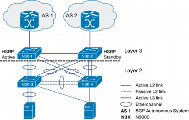
You can deploy the Cisco Nexus 3064 at switch access level or at higher interconnectivity level directly to the exchange layer 3 servers for example, as commonly deployed in High Frequency Trading designs. Figure 1 shows a switched access design, and Figure 2 shows a routed access design.
This guide uses a topology of 4 switches to encompass larger deployment options. The document can be used as reference when deploying a pair or a single Nexus 3064 for smaller scale implementations.
Figure 1. Switched Access Design
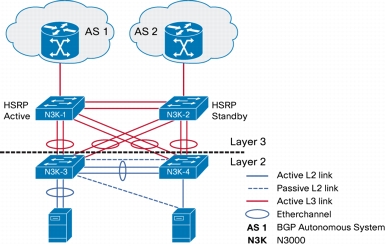
Figure 2. Routed Access Design
Establish Connectivity
Use the management port on the Cisco Nexus 3064 to configure the basic connectivity to the switch.
The configuration is identical to that of the Cisco Nexus 5000 Series Switch:
1. config t
2. interface mgmt 0
3. ip addressip-address subnet mask
4. no shutdown
5. vrf context management
6. ip route 0.0.0.0 0.0.0.0default-gateway-ip-address
7. copy running-config startup-config
An example follows:
n3k-1(config)# int mgmt 0
n3k-1(config-if)# ip address 172.25.186.249/24
n3k-1(config-if)# no shut
n3k-1(config-if)#
n3k-1(config-if)# vrf context management
n3k-1(config-vrf)# ip route 0.0.0.0 0.0.0.0 172.25.186.1
64 bytes from 10.29.176.74: icmp_seq=0 ttl=251 time=1.133 ms
64 bytes from 10.29.176.74: icmp_seq=1 ttl=251 time=0.779 ms
64 bytes from 10.29.176.74: icmp_seq=2 ttl=251 time=0.745 ms
64 bytes from 10.29.176.74: icmp_seq=3 ttl=251 time=0.747 ms
64 bytes from 10.29.176.74: icmp_seq=4 ttl=251 time=0.745 ms
Note: To ping from the management interface, you must add part of the management of Virtual Route Forwarding (VRF), the sub-commands "vrf management".
Layer 2 Deployment
This scenario is similar to deploying four Cisco Nexus 5000 Switches in a Layer 2 configuration
Configure Port Channels
The port-channel configuration commands are common to those of the other Cisco Nexus Operating System (NX-OS) platforms.
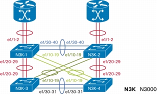
In this example we configure the topology shown in Figure 3.
Figure 3. Physical Port Connectivity
Note: You must enable the Link Aggregation Control Protocol (LACP) feature with the command feature lacp for LACP-negotiated port channels:
1. feature lacp: Enables LACP
2. interface port-channelPO_NUMBER: Creates an interface port channel
3. switchport mode trunk ip addressip-address subnet mask: Defines the port-channel interface as a trunk
4. interface Ethernet 1/number-number: Selects a range of interfaces
5. switchport mode trunk: Defines the interfaces as trunks
6. channel-groupPO_NUMBER [mode active]: Bundles the interfaces in a port channel
6. copy running-config startup-config: Saves the running configuration into bootflash
The configuration follows:
n3k-1(config)# feature lacp
n3k-1(config)# interface port-channel 1
n3k-2(config-if)# switchport mode trunk
n3k-1(config)# interface port-channel 12
n3k-2(config-if)# switchport mode trunk
n3k-1(config)# interface port-channel 13
n3k-2(config-if)# switchport mode trunk
n3k-1(config)# interface port-channel 14
n3k-2(config-if)# switchport mode trunk
n3k-1(config)# int e1/1-2
n3k-1(config-if-range)# switchport mode trunk
n3k-1(config-if-range)# channel-group 1 mode active
n3k-1(config-if-range)# int e1/30-40
n3k-1(config-if-range)# switchport mode trunk
n3k-1(config-if)# channel-group 12 mode active
n3k-1(config-if)# int e1/20-29
n3k-1(config-if-range)# switchport mode trunk
n3k-1(config-if-range)# channel-group 13 mode active
n3k-1(config-if-range)# int e1/10-19
n3k-1(config-if-range)# switchport mode trunk
n3k-1(config-if-range)# channel-group 14 mode active
A similar configuration is repeated on the other devices:
n3k-2(config)# feature lacp
n3k-2(config)# interface port-channel 2
n3k-2(config-if)# switchport mode trunk
n3k-2(config-if)# interface port-channel 12
n3k-2(config-if)# switchport mode trunk
n3k-2(config-if)#interface port-channel 24
n3k-2(config-if)# switchport mode trunk
n3k-2(config-if)# interface port-channel 23
n3k-2(config-if)# switchport mode trunk
n3k-2(config-if)# interface e1/1-2
n3k-2(config-if-range)# switchport mode trunk
n3k-2(config-if-range)# channel-group 2
n3k-2(config-if-range)# interface e1/30-40
n3k-2(config-if-range)# switchport mode trunk
n3k-2(config-if)# channel-group 12 mode active
n3k-2(config-if)# interface e1/20-29
n3k-2(config-if-range)# switchport mode trunk
n3k-2(config-if-range)# channel-group 24 mode active
n3k-2(config-if-range)# interface e1/10-19
n3k-2(config-if-range)# switchport mode trunk
n3k-2(config-if-range)# channel-group 23 mode active
n3k-3(config)# feature lacp
n3k-3(config)# interface port-channel 13
n3k-3(config-if)# switchport mode trunk
n3k-3(config-if)# interface port-channel 34
n3k-3(config-if)# switchport mode trunk
n3k-3(config-if)# interface port-channel 23
n3k-3(config-if)# switchport mode trunk
n3k-3(config-if)# interface e1/20-29
n3k-3(config-if-range)# switchport mode trunk
n3k-3(config-if-range)# channel-group 13 mode active
n3k-3(config-if-range)# interface e1/20-29
n3k-3(config-if-range)# switchport mode trunk
n3k-3(config-if-range)# channel-group 13 mode active
n3k-3(config-if-range)# interface e1/10-19
n3k-3(config-if-range)# switchport mode trunk
n3k-3(config-if-range)# channel-group 23 mode active
n3k-3(config-if-range)# interface e1/30-31
n3k-3(config-if)# switchport mode trunk
n3k-3(config-if)# channel-group 34 mode active
n3k-4(config)# feature lacp
n3k-4(config)# interface po 24
n3k-4(config-if)# switchport mode trunk
n3k-4(config-if)# interface port-channel 14
n3k-4(config-if)# switchport mode trunk
n3k-4(config-if)# interface port-channel 34
n3k-4(config-if)# switchport mode trunk
n3k-4(config-if)# interface e1/10-19
n3k-4(config-if-range)# switchport mode trunk
n3k-4(config-if-range)# interface e1/20-29
n3k-4(config-if-range)# switchport mode trunk
n3k-4(config-if-range)# channel-group 24 mode active
n3k-4(config-if-range)# interface e1/30-31
n3k-4(config-if)# switchport mode trunk
n3k-4(config-if)# channel-group 34 mode active
Traffic Engineering and Spanning Tree
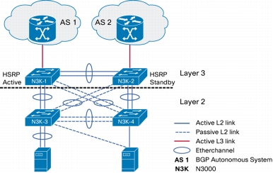
This section describes traffic engineering - how to adjust the traffic path for the Ethernet frames. The configuration example shows how to achieve the logical diagram displayed below in Figure 4.
Figure 4. Switched Access Design Logical Diagram
In the topology shown in Figure 4, N3k-1 is the root switch and N3k-2 the secondary root:
With this configuration of spanning tree, N3k-1 being the root, N3k-4 port-channel 14 will forward traffic, whereas port-channel 24 will block it. If the traffic destined on the hosts behind N3k-4 needs to flow through N3k-2 directly, then you can adjust spanning-tree cost and priority to change the traffic path; for example, you can increase the cost on port-channel 14 on the N3k-4.
The configuration before changes follows:
n3k-4(config-if)# show spanning-tree vlan 1
VLAN0001
Spanning tree enabled protocol rstp
Root ID Priority 24577
Address 0005.73ce.4801
Cost 1
Port 4109 (port-channel14)
Hello Time 2 sec Max Age 20 sec Forward Delay 15 sec
Bridge ID Priority 32769 (priority 32768 sys-id-ext 1)
Address 0005.73ab.2d3d
Hello Time 2 sec Max Age 20 sec Forward Delay 15 sec
Layer 3 capabilities are built into the Cisco Nexus 3064, so you just need to acquire a software license and then enable the features in order to use Layer 3 functions. There are two licenses the Basic and the Enterprise versions. Please refer to the product release notes for further information on licensing.
Install License
1. Find out your host-id:
n3k-1# show license host-id
License hostid: VDH=SSI15040AM0
You must provide your host-id to receive your license file.
2. Copy your license file to bootflash:
Use the command copy to copy your file from your server (ftp, scp, or tftp); for example:
n3k-1# copy ftp: bootflash:
Enter source filename: N3K_SSI1453ATSM.lic
Enter vrf (If no input, current vrf 'default' is considered): management
Enter hostname for the ftp server: 10.10.10.1
Enter username: ftpuser
Password:
***** Transfer of file Completed Successfully *****
Note: You can also copy from a USB drive when it is inserted in the Cisco Nexus 3064 USB port.
Now you can enable the Layer 3 features on the Cisco Nexus 3064.
Note that if you have an enterprise level of license, you must also install the Cisco NX-OS® Software IP Base license.
The Layer 3 functions are enabled with the command feature. The command show feature lists all the options available and the current status of the feature (enabled or disabled).
Steps to Enable Features
1. configure terminal
2. feature A
3. show feature
Examples:
-enable bgp
Use the following command to enable the Border Gateway Protocol (BGP):
n3k-1(config)# feature bgp
n3k-1(config)# show feature | i bgp
bgp 1 enabled (not-running)
-enable ospf
To enable Open Shortest Path First (OSPF), use the following command:
n3k-1(config)# show feature | i ospf
ospf 1 enabled (not-running)
ospf 2 enabled (not-running)
ospf 3 enabled (not-running)
ospf 4 enabled (not-running)
-enable eigrp
To enable Enhanced IGRP (EIGRP), use the following command:
n3k-1(config)# sh feature | i eigrp
eigrp 1 enabled (not-running)
eigrp 2 enabled (not-running)
eigrp 3 enabled (not-running)
eigrp 4 enabled (not-running)
-enable HSRP
n3k-1(config)#feature hsrp
n3k-1(config)# sh feature | i hsrp
hsrp_engine 1 enabled
Configure Layer 3 at Exchange Interconnectivity Layer
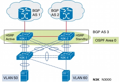
This example shows how to configure Layer 3 on the exchange interconnectivity level on N3K-1 and N3K-2, as shown in Figures 1 and 4.
In this example, HSRP is enabled for VLANs 50 and 60. The hosts on VLANs 50 and 60 behind N3K-3 and N3k-4 can use the HSRP IP as their default gateway IP address.
N3K-1
feature hsrp
vlan 50
name 10.50.1.0
vlan 60
name 10.60.1.0
interface Vlan50
no shutdown
description server-vlan
ip address 10.50.1.2/24
ip ospf passive-interface
ip router ospf 1 area 0.0.0.0
hsrp 1
preempt delay minimum 240
priority 110
timers msec 250 msec 750
ip 10.50.1.1
interface Vlan60
no shutdown
description server-vlan
ip address 10.60.1.2/24
ip ospf passive-interface
ip router ospf 1 area 0.0.0.0
hsrp 1
preempt delay minimum 240
priority 110
timers msec 250 msec 750
ip 10.60.1.1
N3K-2
feature hsrp
vlan 50
name 10.50.1.0
vlan 60
name 10.60.1.0
interface Vlan50
no shutdown
description server-vlan
ip address 10.50.1.3/24
ip router ospf 1 area 0.0.0.0
hsrp 1
preempt delay minimum 240
timers msec 250 msec 750
ip 10.50.1.1
interface Vlan60
no shutdown
ip address 10.60.1.3/24
ip router ospf 1 area 0.0.0.0
hsrp 1
preempt delay minimum 240
timers msec 250 msec 750
ip 10.60.1.1
N3K-1 will be the active router for both VLANs because it has a higher priority.
You can use the command show hsrp to verify.
Configure Multicast with N3K
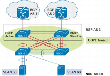
Figure 6. Multicast Switched Server Access Design
This example shows multicast communication between a source and a receiver. It shows allows multicast communication between the Rendezvous Point and the hosts on VLANs 50 and 60. Static or Auto-RP can be utilized.
N3K-1
feature pim
ip pim auto-rp forward listen
interface port-channel1
description to_RP
ip pim sparse-mode
interface port-channel12
description to_N3K-2
ip pim sparse-mode
interface loopback0
ip pim sparse-mode
interface Vlan50
description server-vlan
ip pim sparse-mode
ip pim dr-priority 10
interface Vlan60
description server-vlan
ip pim sparse-mode
ip pim dr-priority 10
N3K-2
feature pim
ip pim auto-rp forward listen
interface port-channel1
description to_RP
ip pim sparse-mode
interface port-channel12
description to_N3K-1
ip pim sparse-mode
interface loopback0
ip pim sparse-mode
interface Vlan50
description server-vlan
ip pim sparse-mode
interface Vlan60
description server-vlan
ip pim sparse-mode
Configure MSDP
You can use MSDP to exchange multicast source information between multiple BGP-enabled PIM sparse-mode domains.
When a receiver for a group matches the group transmitted by a source in another domain, the Rendezvous Point (RP) sends PIM join messages in the direction of the source to build a shortest-path tree. The designated router (DR) sends packets on the source tree within the source domain, which may travel through the route processor in the source domain and along the branches of the source tree to other domains. In domains where there are receivers, route processors in those domains can be on the source tree. The peering relationship is conducted over a TCP connection.
You can configure an MSDP peer when you configure a peering relationship with each MSDP peer that resides either within the current PIM domain or in another PIM domain. MSDP is enabled on the router when you configure the first MSDP peering relationship. Before you begin, ensure that you configured BGP and PIM in the domains of the routers that you will configure as MSDP peers.
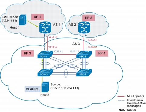
Figure 7. MSDP Peering Between Rendezvous Point in Different PIM Domains
Figure 7 shows three PIM domains. The connected route processors (routers) are called MSDP peers because each one maintains its own set of multicast sources.
Source host 1 sends the multicast data to group 224.1.1.1. On route processor 3 (RP3), the MSDP process learns about the source through PIM register messages and generates Source-Active (SA) messages to its MSDP peers that contain information about the sources in its domain. When RP1 receives the request from host 2 for the multicast data on group 224.1.1.1, it builds a shortest-path tree to the source by sending a PIM join message in the direction of host 1 at 10.50.1.100.
Summary Steps
1. config t
2. feature msdp
3. ip msdp peerpeer-ip-addressconnect-sourceinterface [remote-asas-number]
4. Repeat Step 3 for each MSDP peering relationship.
5. show ip msdp summary [vrfvrf-name | known-vrf-name | all]
6. copy running-config startup-config
The configuration follows:
RP1 (NX-OS)
feature mdsp
ip msdp peer 10.10.1.2 connect-source port-channel 1 remote-as 3
ip msdp password 10.10.1.2 my_peer_password_31
ip msdp sa-interval 80
RP2 (NX-OS)
feature mdsp
ip msdp peer 10.10.2.2 connect-source port-channel 1 remote-as 3
ip msdp password 10.10.2.2 my_peer_password_42
ip msdp sa-interval 80
RP3 (N3K-1)
feature mdsp
ip msdp peer 10.10.1.1 connect-source port-channel 1 remote-as 1
ip msdp peer 10.12.1.2 connect-source port-channel 12
ip msdp password 10.10.1.1 my_peer_password_31
ip msdp sa-interval 80
ip mdsp mesh-group 10.12.1.2 mesh_group_34
RP4 (N3K-2)
feature mdsp
ip msdp peer 10.10.2.1 connect-source port-channel 1 remote-as 2
ip msdp password 10.10.2.1 my_peer_password_42
ip msdp sa-interval 80
ip mdsp mesh-group 10.12.1.1 mesh_group_34
Verification
show ip msdp summary [vrfvrf-name|known-vrf-name| all]
Example:
[snip]
MSDP peer 10.10.1.1 for VRF "default"
AS 1, local address: 10.10.1.2 (port-channel1)
Description: none
Connection status: Established
Uptime(Downtime): 00:03:30
[snip]
Configure Layer 3 at Access Layer
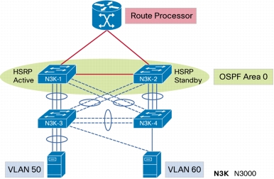
Another possible design is to configure Layer 3 to the access layer as illustrated in Figures 8 and 9.
The configuration of N3k-3 and N3k-4 in this topology is similar as that for N3K-1 and N3K-2 in the previous example (Figures 1 and 5).
Figure 8. Layer 3 Design at Server Access Layer
Figure 9. Layer 3 Server Access Design Protocol View
Configure Layer 2 and Layer 3 Jumbo MTU
This section describes how to change the maximum-transmission-unit (MTU) size for Layer 2 frames or Layer 3 packets. The MTU changes do not require a switch reboot, and they take effect immediately.
Layer 2 Jumbo MTU
Layer 2 jumbo MTU configuration is similar across all Cisco Nexus NX-OS platforms.
The default MTU size is 1500 bytes on the Cisco Nexus 3064. To allow a higher MTU size (jumbo), you must change the configuration.
Use the following command to verify the Layer 2 MTU size:
n3k-1# sh queuing int e1/1
Ethernet1/1 queuing information:
TX Queuing
qos-group sched-type oper-bandwidth
0 WRR 100
RX Queuing
qos-group 0
HW MTU: 1500 (1500 configured)
[snip]
n3k-1#
The configuration follows:
n3k-1#configure terminal
n3k-1(config)# policy-map type network-qos jumbo
n3k-1(config-pmap-nq)# class type network-qos class-default
n3k-1(config-pmap-nq-c)# mtu 9216
n3k-1(config-pmap-nq-c)# system qos
n3k-1(config-sys-qos)# service-policy type network-qos jumbo
• A maximum of four active sessions simultaneously:
– Two sessions with source interfaces monitoring in both directions
– Four sessions when monitored traffic is in only one direction (RX or TX)
• Up to 18 configured sessions, allowing easier configuration changes
The best practice is to use only the RX type of source traffic for Switched Port Analyzer (SPAN) to provide better performance: RX traffic is cut-through, whereas TX is store-and-forward. Hence, when monitoring both directions (RX and TX), the performance is not as good as when monitoring only RX. If you need to monitor both directions of traffic, you can monitor RX on more physical ports to capture both sides of the traffic.
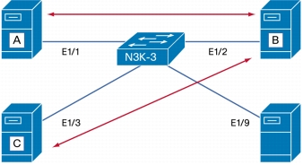
Example: Monitor bidirectional traffic to and from server B.
The goal in this example (Figure 10) is to monitor traffic going to server B in both directions. The other devices communicating with server B are servers A and C. The SPAN destination client to receive the traffic is also connected to the Cisco Nexus 3064PQ. To achieve better performance, the configuration needs to monitor RX traffic on three ports: Ethernet 1/1, 1/2, and 1/3 instead of just Ethernet 1/2 (both directions).
Note: If more than the four SPAN resources are used (two bidirectional or four unidirectional SPAN sessions), the following error message will be displayed when you attempt to bring up the monitor session with the no shutdown command:
"ERROR: Destination resource unavailable. All destination resources used up."
It's also possible to monitor a VLAN as a source traffic or a port-channel.