The Cisco® ONS 15454 Multiservice Transport Platform (MSTP) provides a comprehensive, intelligent dense wavelength-division multiplexing (DWDM) solution for expanding metropolitan (metro) and regional bandwidth.
Product Overview
The Cisco ONS 15454 MSTP offers optical amplifiers for extending the reach of a metro or regional network. The optical amplifier cards are part of the Cisco ONS 15454 MSTP intelligent DWDM architecture engineered to reduce DWDM complexity and speed the deployment of next-generation networking solutions.
The Cisco ONS 15454 optical amplifier cards (Figure 1) are plug-in modules that take advantage of proven Cisco ONS 15454 carrier-class features. These cards deliver the reach and optical performance to support a single DWDM channel all the way to 40 channels today (designed for 80-wavelength operation) - to meet the requirements of service provider and enterprise networks. Table 1 outlines the optical amplifier plug-in card types available for the Cisco ONS 15454 MSTP with the applications they are designed to support.
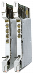
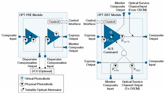
Figure 1. Cisco ONS 15454 Optical Booster Amplifier (part number OPT-BST) and Optical Preamplifier (part number OPT-PRE)
Table 1. Optical Amplifier Cards with Applications
Component
Deployment Application
Optical preamplifier (OPT-PRE)
This product amplifies the incoming composite DWDM signal to allow a sufficient optical power level to optical receivers on dropped wavelengths and to overcome the insertion losses of optical filters in the node. It employs a two-stage amplifier design to allow insertion of dispersion-management devices to compensate for pulse spreading at higher multiplexer speeds. Deployment locations include any site that requires additional signal level.
Optical booster amplifier
(OPT-BST)
This product amplifies the outgoing composite DWDM signal to overcome the attenuation of the fiber network. It integrates an optical service channel splitter or combiner to allow the optical supervisory channel (OSC) to be sent to and received from the optical service channel module (OSCM) card. Deployment locations include any site that requires additional signal level.
17-dB gain amplifier
(OPT-AMP-17C)
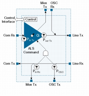
This flexible amplifier can be used as a preamplifier or as a booster amplifier. It integrates an optical service channel splitter or combiner to allow the OSC to be sent to and received from the OSCM card.
The Cisco ONS 15454 optical amplifiers take advantage of the latest in amplifier technology, variable optical attenuators, photo diodes, and extensive software to facilitate a high degree of automation for simplified operations. They feature low-noise-gain blocks for C-band optical-amplification requirements. For flexibility of application support, the amplifiers support two modes of operation, constant gain and constant power. They also provide fast-transient suppression to respond quickly to network changes without adding impairments and degradation. Each card integrates software-controllable variable optical attenuators (VOAs) along with extensive optical monitoring with photo diodes, to provide nodal- and network-based automatic power-level management. Extensive optical safety algorithms provide user safety when operating the network.
The optical amplifier cards incorporate faceplate-mounted LEDs to provide a quick visual check of the operational status at the card. Printed on each of the faceplates is an icon, an orange circle, which corresponds to shelf-slot icons located on the shelf assembly, indicating the shelf slot where the cards can be inserted. The cards are supported by the integrated Cisco Transport Controller craft manager, which provides the user access for operations, administration, maintenance, and provisioning (OAM&P) for the system.
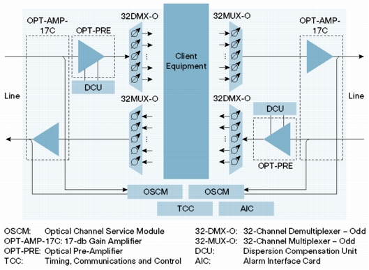
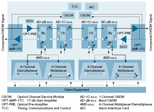
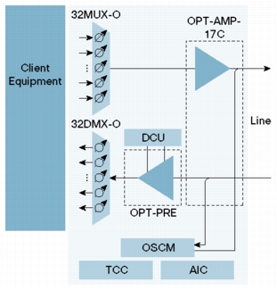
Selection and deployment of the optical amplifiers depend on the requirements of the network. The Cisco TransportPlanner optical design tool is available to assist in the engineering, bill-of-material development, and deployment of the DWDM network. Figures 2 through 4 show sample signal-flow diagrams for a selection of Cisco ONS 15454 MSTP node types, outlining the use for each amplifier type.
Tables 2 through 7 give specifications for the Cisco ONS 15454 optical filters. Figure 5 provides the functional diagrams for the Cisco ONS 15454 optical filters.
Table 2. Regulatory Compliance1
Countries Supported
ANSI System
ETSI System
• Canada
• United States
• Korea
• Japan
• European Union
• European Union
• Africa
• CSI
• Australia
• New Zealand
• China
• Korea
• India
• Saudi Arabia
• South America
EMC (Class A)
• ICES-003 Issue 3 (1997)
• GR-1089-CORE, Issue 3
• FCC 47CFR15 subpart B (2004)
• EN 300 386 v1.3.3
• CISPR22 (2005) and CISPR24 (+ Am 1, Am.2 2002)
• EN55022 and EN55024
Safety
• UL/CSA 60950 -1 First Edition (2003)
• GR-1089-CORE , Issue 3
• UL /CSA 60950 -1 First Edition (2003)
• IEC 60950 -1 (2001-01) First Edition/EN60950 -1 (2001), First Edition
Laser
• UL/CSA 60950 -1 First Edition (2003)
• IEC 60950 -1 (2001-01) First Edition/EN60950 -1 (2001), First Edition
• IEC 60825-2 (2004-06), Third Edition
• CDRH (Accession letter and report)
• IEC 60825-1 +Am.1+ Am.2 (2001)
Environmental
• GR-63-CORE, Issue 2 and Issue 3
• ETS 300-019-2-1 V2.1.2 (Storage, Class 1.1)
• ETS 300-019-2-2 V2.1.2 (Transportation, Class 2.3)
• ETS 300-019-2-3 V2.1.2 (Operational, Class 3.1E)
1. All compliance testing and documentation may not be completed at release of the product. Check with your sales representative for countries outside of Canada, the United States, and the European Union.
Table 3. System Requirements
Component
Cisco ONS 15454 SONET/ANSI
Cisco ONS 15454 SDH/ETSI
Processor
TCC2 or TCC2P
TCC2 or TCC2P
Cross-connect
All (not required)
All (not required)
Shelf assembly
15454-SA-ANSI or 15454-SA-HD shelf assembly with FTA3 or FTA4 version fan-tray assembly
15454-SA-ETSI shelf assembly with SDH 48V or FTA4 fan-tray assembly
System software
Release 4.6.0 SONET or later
Release 4.6.0 SDH or later
Table 4. Common Amplifier Specification
Specification
OPT-PRE
OPT-BST
Management
Card LEDs
• Failure (FAIL)
• Signal fail (SF)
Red
Yellow
Red
Yellow
Operating environment
Temperature
23 to 131°F
-5 to 55°C
23 to 131°F
-5 to 55°C
Humidity
5 to 95% noncondensing
5 to 95% noncondensing
Storage environment
Temperature
23 to 131°F
-5 to 55°C
23 to 131°F
-5 to 55°C
Humidity
5 to 95% noncondensing
5 to 95% noncondensing
Figure 5. Functional Diagrams for Optical Preamplifier and Optical Booster Amplifiers
Figure 6. Functional Diagrams for Optical Amplifier 17dB Gain
Table 5. Optical Amplifier Specifications
Specification
OPT-PRE
OPT-BST
OPT-AMP-17C
Optical Parameters
Input power range (Pin)
• Full-channel loading
• 1-channel loading
-21.5 to 12 dBm
-39.5 to -6 dBm
-3 to 12 dBm
-21 to -6 dBm
-6 to 3 dBm
-28 to -19 dBm
Output power (Pout maximum)
17.5 dBm
17.5 dBm
17.5 dBm
Gain range
5 to 38.5 dB
5 to 20 dB
14 to 23 dB
Gain ripple (peak to valley)
1.5 dB
1.5 dB
1.5 dB
Gain and power regulation
• Over- and under-shoot
0.5 dB
0.5 dB
0.5 dB
Noise figure (at Gain ≥ 20 dB)
6.5 dB
6 dB
5.5 dB
Midstage insertion loss range for Dispersion Compensation Unit (DCU)