The Cisco® ONS 15454 Multiservice Transport Platform (MSTP) provides a comprehensive, intelligent dense wavelength-division multiplexing (DWDM) solution for expanding metropolitan (metro) and regional bandwidth.
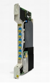
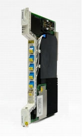
Figure 1. 40-Channel Single-Module ROADM with Integrated Optical Pre-Amplifier (40-SMR1-C) and Optical Pre-Amplifier and Boost Amplifier (40-SMR2-C)
Product Overview
Release 9.1 of the Cisco ONS 15454 MSTP expands the platform's reconfiguration options. In addition to the existing 32-channel and 40-channel reconfigurable optical add/drop multiplexer (ROADM) cards, two new cards (Figure 1) are introduced in this release to optimize and increase the MSTP's throughput density. By integrating multiple features on the same card (optical service channel [OSC], amplification, and ROADM), the single-module ROADM (SMR) cards are so compact that they can be added to any node in the network, extending optical add/drop multiplexing to the edge.
The new 40-channel single-module ROADM with integrated optical pre-amplifier (part number 40-SMR1-C) combines the OSC add/drop filter, a pre-amplifier, and a 2x1 wavelength selective switch (WSS)-based ROADM core into a single-slot unit. This unit is optimized for Degree-2 reconfigurable nodes.
The 40-channel single-module ROADM with integrated optical pre-amplifier and boost amplifier (part number 40-SMR2-C) includes the OSC add/drop filter, pre- and boost amplifiers, and a 4x1 WSS-based ROADM core. This unit provides an effective way to support multi-degree nodes up to Degree-4, allowing in-service upgrade from Degree-2 up to Degree-4 at a very competitive price point.
Similarly to the already available 40-channel wavelength cross-connect (40-WXC) card, and thanks to the software functionalities extended from previous releases, the 40-SMR2-C card provides multi-degree switching capabilities at the individual wavelength level. Mesh and multi-ring network topologies can now be deployed using the Cisco ONS 15454 MSTP with complete flexibility of service routing at all nodes in the network.
Individual channels separation, required on the add/drop ports to terminate local traffic, is provided by the new Cisco ONS 15216 40-channel multiplexer/demultiplexer patch panel (odd channels). The use of athermal Arrayed Waveguide Grating (AWG) technology allows the removal of the multiplexer and demultiplexer function from the Cisco ONS 15454 MSTP shelf. This approach provides many benefits to customers, including:
• Simplified connectivity to passive patch-panels: 4 LC cables instead of 20 MPO cables.
• Improved density: passive multiplexing and demultiplexing frees up slots in the main chassis to be used for traffic.
Single-module ROADM (SMR) units increase the density of the Cisco ONS 15454 MSTP. An SMR1-based Degree-2 node can increase a single-shelf throughput by 500 percent compared to the supported throughput in Release 9.0 (200 Gbps vs. 40 Gbps), as the additional free slots can be used to install transponder cards. A similar improvement can be obtained in Degree-4 nodes. A 40-WXC-based Degree-4 node requires two shelves for the common optics without any available slot for the transponder. An SMR2-based Degree-4 node provides 400 Gbps of traffic in the same two shelves, or 120 Gbps of traffic when installed into a single shelf. See Table 1 for details.
Table 1. Shelf Throughput Comparison for 40-Channel ROADM Cards
Node Type
Card Type
Required Shelves
Free Slots1
Equivalent 10 Gbps Transponder-Based Local Add/Drop Traffic2
Degree-2
40-WSS
1
2
40 Gbps
40-SMR1
1
10
200 Gbps
Degree-4
40-WXC
2
0
0 Gbps
40-SMR2
1
6
120 Gbps
2
20
400 Gbps
1. Based on current 17-slot MSTP chassis
2. Using 15454-OTU2-XP card
The Cisco ONS 15454 ROADM cards are plug-in modules that take advantage of the proven Cisco ONS 15454 carrier-class features to deliver the flexibility to access network bandwidth from a single DWDM channel all the way to 112 channels, to support the requirements of service provider and enterprise networks. Table 2 provides deployment details.
Table 2. 40-Channel ROADM Deployment Information
Component
Deployment Application
40-channel single-module ROADM with integrated optical pre-amplifier - C band - odd channels
This is the key unit for the Degree-2 single-module ROADM solutions operating in the C band, odd channels. It allows the possibility to remotely and automatically control a wavelength to bypass or be added in a node of the network.
The unit includes a 2-stage pre-amplifier that allows the insertion of dispersion-management devices to compensate for pulse spreading at higher multiplexer speeds. Automatic per-channel power monitoring and control capabilities embedded in the unit (Dynamic Gain Equalization - DGE) improve overall system performance.
Used in conjunction with the Cisco ONS 15216 40-Channel Multiplexer/Demultiplexer Patch Panel Odd, it allows management of the local add/drop traffic.
40-channel single-module ROADM with integrated optical pre-amplifier and boost amplifier - C band - odd channels
This is the key unit to provide a Degree-2 solution that can scale, in-service, to a Degree-4 multi-degree ROADM solution operating in the C band, odd channels. When installed in conjunction with the 4-Degree single-module ROADM mesh patch panel, it allows the possibility to remotely and automatically control a wavelength to be routed to any of the 4 directions of a multi-degree ROADM node.
Unit includes a 2-stage pre-amplifier that allows the insertion of dispersion-management devices to compensate for pulse spreading at higher multiplexer speeds and a booster amplifier to increase the power of outgoing composite DWDM signal to overcome the attenuation of the fiber network. Automatic per-channel power monitoring and control capabilities embedded in the unit (Dynamic Gain Equalization - DGE) improve overall system performance.
Used in conjunction with the Cisco ONS 15216 40-Channel Multiplexer/Demultiplexer Patch Panel Odd, it allows you to manage the local add/drop traffic of the specific direction supported by the 40-SMR2 unit.
Cisco ONS 15216 40-channel multiplexer/demultiplexer patch panel (odd)
This passive 2-rack-unit (2RU) is used in Degree-2 and multi-degree ROADM nodes based on the 40-SMR1-C and 40-SMR2-C to manage the local add/drop function on the specific direction(s) supported by the 40-SMR1-C and 40-SMR2-C units.
This passive 1RU is used in multi-degree ROADM nodes with up to four 40-SMR2-C units to provide broadcast functionalities and replicate to all the directions of the node the wavelengths to be routed through the ROADM node.
The Cisco ONS 15454 single-module ROADM cards (40-SMR1-C and 40-SMR2-C) operate on the ITU 100-GHz wavelength plan. Each card integrates automatic per-channel power monitor and control capabilities, providing node- and network-based automatic-power-level management on each input and output port. Per-channel optical path selection is also done in a completely automated way through Wavelength Path Provisioning (WPP) at the network level, featuring end-to-end, point-and-click wavelength provisioning and easy SONET/SDH-like wavelength management.
The ROADM node architecture has been specifically defined and engineered to provide:
• High reliability - Enables complete independence between specific direction-facing units with the possibility to house units in physically separated shelves.
• Automatic optical power balancing - Per-channel automatic power control allows a "self-healing" intelligent approach to DWDM, which is unique in the market.
• Low insertion loss - Selected technology allows direct integration of different functionalities in the same optical module, reducing to the bare minimum the number of optical connections.
• Reduced footprint - SMR units integrate multiple functions into a single card (amplification, OSC add/drop, ROADM, and power monitoring), reducing node power consumption and increasing shelf throughput.
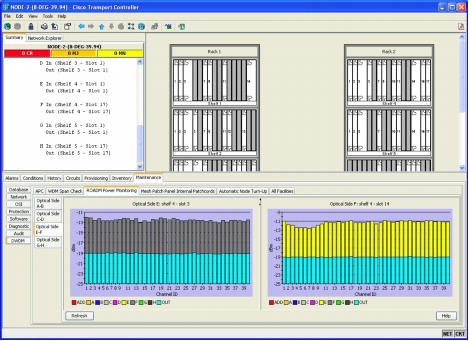
The optical cards incorporate faceplate-mounted LEDs to provide a quick visual check of the operational status at the card. Printed on each of the faceplates is an icon, an orange circle, which is mapped to shelf-slot icons indicating the shelf slot where the card can be physically installed. The cards are supported by the integrated Cisco ONS 15454 Cisco Transport Controller craft manager, which provides the user access for operations, administration, maintenance, and provisioning (OAM&P) for the system. Taking advantage of the embedded units' capabilities, Cisco Transport Controller can also provide a per-channel graphical representation of the optical power levels associated with each individual path in the ROADM nodes (Figure 2).
Figure 2. Cisco Transport Control Per-Channel Optical Power Monitoring Representation
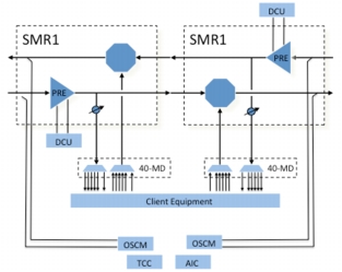
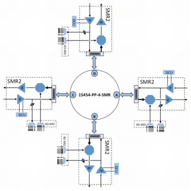
Complete flexibility provided by the single-module ROADM units greatly simplifies the design of optical networks in terms of unit placement. However this flexibility alone is not enough to allow users to define any possible optical path at the network level. The Cisco Transport Planner (CTP) optical design tool features the possibility to design DWDM networks based on ROADM functionalities and to verify all the possible optical paths and the DWDM interface types defined by the user. A truly flexible network design resulting from the selection of both optical paths and DWDM interface types is highly customizable by the user, who can compare different solutions and create hypothetical scenarios in a simple and effective way.
Figure 3 and Figure 4 show sample signal-flow diagrams for Cisco ONS 15454 MSTP Single-Module ROADM nodes, outlining the use for each unit type.
1. All compliance testing and documentation may not be completed at release of the product. Check with your sales representative for countries outside of Canada, the United States, and the European Union.
Table 4. System Requirements
Component
Cisco ONS 15454 ANSI
Cisco ONS 15454 ETSI
Processor
TCC2P/TCC2
TCC2P/TCC2
Cross-connect
All (not required)
All (not required)
Shelf assembly
15454-SA-HD or 15454-SA-HD-DDR shelf assembly with CC-FTA or FTA3 version fan-tray assembly
15454-SA-ETSI shelf assembly with CC-FTA or SDH 48V fan-tray assembly
System software
Release 9.1.0 ANSI or later
Release 9.1.0 ETSI or later
Table 5. Specifications for Single-Module ROADM Cards
Specification
40-SMR1-C
40-SMR2-C
Management
Card LEDs
• Failure (FAIL)
• Active/standby (ACT/STBY)
• Signal fail (SF)
Red
Green/yellow
Yellow
Red
Green/yellow
Yellow
Operating Environment
Temperature
• Normal
• Short term1
0ºC to 40°C (32°F to 104°F)
-5ºC to 55ºC (23ºF to 131ºF)
0ºC to 40°C (32°F to 104°F)
-5ºC to 55ºC (23ºF to 131ºF)
Relative humidity
• Normal
• Short term1
5% to 85%, non condensing
5% to 90% RH but not to exceed 0.024 kg water/kg of dry air
5% to 85%, noncondensing
5% to 90% RH but not to exceed 0.024 kg water/kg of dry air
Storage Environment
Temperature
-40°C to 70°C (-40°F to 158°F)
-40°C to 70°C (-40°F to 158°F)
Relative humidity
5% to 95% RH
5 to 95% RH
1. Short-term refers to a period of not more than 96 consecutive hours and a total of not more than 15 days in 1 year. This refers to a total of 360 hours in any given year, but no more than 15 occurrences during that 1-year period.
Table 6. Optical Specifications for Single-Module ROADM Cards
Specification
40-SMR1-C
40-SMR2-C
Optical Parameters
Insertion loss (maximum at minimum VOA)
7.0 dB (EXP-RX - LINE-TX and
ADD-RX - LINE-TX)
6.0 dB (EXPi1-RX - LINE-TX and
ADD-RX - LINE-TX)
Minimum VOA dynamic range
25 dB (EXP-RX - COM-TX)
30 dB (LINE-RX - DROP-TX)
25 dB (EXPi-RX - COM-TX)
30 dB (LINE-RX - DROP-TX)
Maximum input power
27 dBm
27 dBm
Filter type
Wavelength selective switch
Wavelength selective switch
Minimum transmit filter -1.5 dB bandwidth (all operating conditions and attenuation values)
+/-200 pm (EXP-RX - LINE-TX and
ADD-RX - LINE-TX)
+/-200 pm (EXPi-RX - LINE-TX and
ADD-RX - LINE-TX)
Adjacent crosstalk
(all operating conditions and attenuation values)
37 dB (minimum)
37 dB (minimum)
Non-adjacent crosstalk
(all operating conditions and attenuation values)
45 dB (minimum)
45 dB (minimum)
Maximum Polarization Dependent Loss (PDL) (all operating conditions and attenuation values)
0.8 dB (any path)
0.8 dB (any path)
Optical power setting accuracy
(all operating conditions and attenuation values)
-0.5/0.5 dB
-0.5/0.5 dB
Minimum return loss
40 dB
40 dB
Optical Parameters - Pre-Amplifier Section
Input power range (pin)
• Full-channel loading
• 1-channel loading
-21 to 12 dBm
-43 to -10 dBm
-21 to 12 dBm
-43 to -10 dBm
Output power (POUT maximum)
+17.5 dBm
+17.5 dBm
Gain range
5 to 38 dB
5 to 38 dB
Gain ripple (peak to valley)
1.2 dB
1.2 dB
Gain and power regulation
• Over- and under-shoot
0.5 dB
0.5 dB
Max noise figure (at g≥ 21 dB)
7.5 dB
7.5 dB
Midstage insertion loss range for Dispersion Compensation Unit (DCU)
0 to 9 dB
0 to 9 dB
Transient suppression
Yes
Yes
Optical Parameters - Boost Amplifier Section
Input power range (pin)
• Full-channel loading
• 1-channel loading
-
+12 dBm
-5 dBm
Output power (Pout maximum)
-
17.5 dBm
Gain range
-
13 to 26 dB
Gain ripple (peak to valley)
-
1.2 dB
Gain and power regulation
• Over- and under-shoot
-
0.5 dB
Max noise figure (at gain ≥ 17 dB)
-
6 dB
Optical Parameters - OSC Section
OSC filter type
Interferential
Interferential
Max OSC filter insertion loss
1.8 dB (LINE-RX - OSC-TX)
1.3 dB (OSC-RX - LINE-TX)
1.8 dB (LINE-RX - OSC-TX)
1.3 dB (OSC-RX - LINE-TX)
OSC filter passband
1500 to 1520 nm
1500 to 1520 nm
Connectors
Connectors type
LC (all the ports)
MPO (EXP-RXi and EXP-TX ports)
LC (all the other ports)
Power
Card power draw
• Typical
• Maximum
30W
60W
35W
70W
Physical
Size
1 slots
1 slot
Supported shelf slots
1-6, 12-17
1-6, 12-17
1. EXPi-RX, where i goes from 1 to 3.
Table 7. Optical Specifications for Mesh Patch Panel Units
Specification
15454-PP-4-SMR
Maximum Insertion Loss
7.5 dB
Maximum Polarization Dependent Loss
0.1 dB
Maximum PMD
0.1 ps
Minimum Return Loss
50 dB
Ordering Information
Table 8 gives ordering information for the 40-channel Cisco ONS 15454 single-module ROADM units.
Table 8. System Ordering Information
Part Number
Description
15454-40-SMR1-C=
40Chs Single Module ROADM with integrated Optical PRE Amplifier
15454-40-SMR2-C=
40Chs Single Module ROADM with integrated Optical PRE, Boost Amplifier
15454-MPO-XMPO-2=
Multi-fiber patchcord - MPO to MPO Crossed - 2m
15454-PP-4-SMR=
1 RU 4-Degree SM ROADM Mesh Patch Panel
15216-MD-40-ODD=
ONS 15216 40ch Mux Demux Patch Panel Odd
15454-MPO-MPO-2=
Multi-fiber patchcord - MPO to MPO - 2m
15454-MPO-MPO-4=
Multi-fiber patchcord - MPO to MPO - 4m
15454-MPO-MPO-6=
Multi-fiber patchcord - MPO to MPO - 6m
15454-MPO-MPO-8=
Multi-fiber patchcord - MPO to MPO - 8m
Service and Support
Cisco offers a wide range of services programs to accelerate customer success. These innovative services programs are delivered through a unique combination of people, processes, tools, and partners, resulting in high levels of customer satisfaction. Cisco services help you to protect your network investment, optimize network operations, and prepare your network for new applications to extend network intelligence and the power of your business.