This product bulletin highlights features in Cisco IOS® Software Release 12.2(18)SXE and includes the following sections:
1. Cisco IOS Software Release 12.2S introduction
2. Cisco IOS Packaging in Release 12.2(18)SXE
3. Release 12.2(18)SXE Hardware and Feature Highlights
1. CISCO IOS SOFTWARE RELEASE 12.2S INTRODUCTION
Cisco IOS Software Release 12.2S is designed for Enterprise campus and Service Provider edge networks that require world-class IP and Multiprotocol Label Switching (MPLS) services. The Cisco Catalyst® Switches and high-end routers in Release 12.2S provide secure, converged network services in the most demanding Enterprise and Service Provider environments, from the wiring closet and data center to the WAN aggregation edge.
The infrastructure innovation and technology leadership in Cisco IOS 12.2S enable advanced Ethernet LAN switching, Metro Ethernet, and Broadband Aggregation services through enhancements in High Availability, Security, MPLS, VPNs, and IP Routing and Services.
Derived from Release 12.2(14)S, 12.2SX provides Release 12.2S functionality features and hardware support for the Cisco Catalyst 6500 Series Switch and Cisco 7600 Series Router.
In addition to Release 12.2(18)SXE, Releases 12.2(18)SXD, 12.2(17d)SXB, 12.2(17b)SXA, 12.2(17a)SX, and 12.2(14)SX are available from Cisco.com. For detailed information about the features and hardware supported in each of these releases, please visit:
1.1 Release 12.2SX Ordering Information, Feature Sets, and Image Names
Refer to the "Feature Sets" section of the Release 12.2SX release notes for information about Release 12.2SX orderable product numbers, feature sets, and image names.
Cisco IOS Software is the world's leading network infrastructure software, delivering a seamless integration of technology innovation, business-critical services, and hardware support. Currently operating on over ten million active systems, ranging from the small home office router to the core systems of the world's largest service provider networks, Cisco IOS Software is the most widely leveraged network infrastructure software in the world.
Today's users need more flexible and consistent software packaging to address their complex network environments. Cisco is expanding its new Cisco IOS Packaging to Cisco switches via Cisco IOS Software Release 12.2S, creating a new foundation for Cisco IOS Software features and functionality.
For an overview of Cisco IOS Packaging for Cisco switches, including its availability and the associated Cisco IOS Software Release migration strategy, please visit: http://www.cisco.com/go/packaging/
3. RELEASE 12.2(18)SXE HARDWARE AND FEATURE HIGHLIGHTS
Cisco IOS Software Release 12.2(18)SXE, the latest customer release of Release 12.2S, adds support for powerful new hardware and more than 100 new features for the Cisco Catalyst 6500 Series Switch and Cisco 7600 Series Router.
3.1 Release 12.2(18)SXD Hardware and Feature Highlights
Table 1 and the following sections highlight some of the key hardware and software features available in Release 12.2(18)SXE.
Note: Unless noted otherwise, the following highlighted features were first supported in Release 12.2SX as of Release 12.2(18)SXE. Subsequent releases of Release 12.2SX will also support the highlighted features, and might include additional hardware support for the following highlighted features.
Cisco Feature Navigator, which requires an account on Cisco.com, dynamically updates the list of supported hardware as new hardware support is added for the features in the releases of Release 12.2SX. Cisco Feature Navigator can provide a cumulative list of all new and existing features supported in Release 12.2(18)SXE, including hardware and software image support.
Table 1. Release 12.2(18)SXE Hardware and Feature Highlights
Hardware Support
Cisco IOS Security
Cisco IOS Infrastructure
IP Addressing and Services
• Cisco Services SPA Carrier-400
• Cisco IPsec VPN SPA
• WebVPN Service Module
• Cisco 7604 Router
• Cisco 7600 Series SPA Interface Processor 400
• Cisco 7600 Series SPA Interface Processor 200
• WS-C6504-E
• 2700 Watt AC Power Supply for the Cisco 7606
• 2700 Watt DC Power Supply for the Cisco 7606
• 2700 Watt AC Power Supply for the Cisco 7604
• 2700 Watt AC Power Supply for the Cisco 7604
• Cisco 1-Port OC-12c/STM-4c ATM Shared Port Adaptor
• Cisco 2-Port OC-3c/STM-1c ATM Shared Port Adapter
• Cisco 4-Port OC-3c/STM-1c ATM Shared Port Adapter
• Cisco 1-Port OC-12c/STM-4c POS Shared Port Adapter
• Cisco 2-Port OC-3c/STM-1c POS Shared Port Adapter
• Cisco 4-Port OC-3c/STM-1c POS Shared Port Adapter
• Cisco 2-Port Clear Channel T3/E3 Shared Port Adapter
• Cisco 4-Port Clear Channel T3/E3 Shared Port Adapter
• Cisco 2-Port Channelized T3 (DS0) Shared Port Adapter
• Cisco 4-Port Channelized T3 (DS0) Shared Port Adapter
• Cisco 8-Port Channelized T1/E1 Shared Port Adapter
• 1-Port Fast Ethernet Port Adapter
• 2-Port Fast Ethernet Port Adapter
• 1-Port Packet over SONET OC3c/STM1 Port Adapter
• Dynamic Multipoint VPN
• VPN Routing and Forwarding-Aware Dynamic Multipoint VPN
• IPv4 Multicast over Point-to-Point Generic Routing Encapsulation
• Multicast over Virtual Routing and Forwarding Lite
• Cisco IOS Source Specific Multicast Mapping
• IPv6 Protocol Independent Multicast-Sparse Mode
• IPv6 Source Specific Multicast
• Multicast Listener Discovery v1 and v2
• IPv6 Multicast Explicit Host Tracking
• Source Specific Multicast Mapping for Multicast Listener Discovery version 1
• IPv6 Multicast Boot Strap Router Support
• Bidirectional Forwarding Detection
• BGP Multipath Load Sharing for Both External BGP and Internal BGP in a Multiprotocol Label Switching VPN
• BGP Support for TTL Security Check
• EIGRP Multiprotocol Label Switching VPN PE-CE Site of Origin
• IS-IS Support for Priority-Driven IP Prefix RIB Installation
• OSPF Link State Database Overload Protection
3.2 Hardware Support
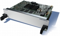
Cisco Services SPA Carrier-400 (SSC-400)
The Cisco Services SPA Carrier-400 (SSC-400) helps enable high-performance IPsec VPN services for secure transport of mission-critical data across the network. It provides enterprises and service providers tremendous flexibility and density as they scale their network infrastructure and expand secure, remote services to branch offices and offsite users. The SSC-400 has 2 sub slots for the IPsec VPN SPA, providing a total throughput of 5 Gbps of IPsec encryption acceleration per chassis slot.
Figure 1. Cisco Services SPA Carrier-400
Benefits
• Modularity-Up to two Cisco IPsec VPN SPAs per SSC-400, creating investment protection and offers flexibility across Cisco 7600 Series Router and Cisco Catalyst 6500 Series Switches.
• Scalability-Up to 5 SSC-400 and 10 IPsec VPN SPAs in a Cisco 7600 Series Router or Cisco Catalyst 6500 chassis, offering high-density, high-performance IPsec VPN services while maintaining attractive footprint and tremendous scalability.
Hardware
• Routers-Cisco 7600 Series
• Switches-Cisco Catalyst 6500 Series
Considerations
Requires Cisco IOS Software Release 12.2(18)SXE2 or later.
The Cisco IPsec VPN SPA delivers scalable and cost-effective VPN performance for Cisco Catalyst 6500 Series Switches and the Cisco 7600 Series Router. Using the Cisco 7600 Series Router or Cisco Catalyst 6500 Series Services SPA Carrier-400 (Cisco Services SPA Carrier-400), each slot of the Cisco Catalyst 6500 or Cisco 7600 Series Router can support up to two IPsec VPN SPAs. The Cisco IPsec VPN SPA delivers next-generation AES encryption standards as well as increased performance of up to 2.5 Gbps IPsec encryption acceleration.
Figure 2. Cisco IPsec VPN SPA
Benefits
• Next-generation Encryption Technology-In addition to supporting Data Encryption Standard (DES) and Triple Data Encryption Standard (3DES), the Cisco IPsec VPN SPA supports Advanced Encryption Standard (AES), including all key sizes (128-, 192-, and 256-bit keys). Designed to be the next-generation encryption technology, AES offers the ultimate in IPsec VPN security and interoperability.
• High-speed VPN Performance-High-speed VPN performance provides up to 2.5 Gbps of AES and 3DES IPsec throughput with large packets and 1.6 Gbps with Internet mix (IMIX) traffic.
• Scalability-Up to 10 Cisco IPsec VPN SPAs can be installed in a system to provide up to 25 Gbps of total throughput, enabling wire-speed secured transport for native 10-Gigabit Ethernet interfaces.
• Comprehensive VPN Features-The Cisco IPsec VPN SPA provides hardware acceleration for both IPsec and generic routing encapsulation (GRE), comprehensive support of site-to-site IPsec, remote-access IPsec, and certificate authority/public key infrastructure (CA/PKI).
• VPN Resiliency and High Availability-Routing over IPsec tunnels, dead-peer detection (DPD), Hot Standby Router Protocol (HSRP) plus reverse route injection (RRI), and intra-chassis and inter-chassis stateful failover for both IPsec and GRE provide superior VPN resiliency and high availability.
Hardware
• Routers-Cisco 7600 Series
• Switches-Cisco Catalyst 6500 Series
Considerations
Requires Cisco IOS Software Release 12.2(18)SXE2 or later.
The Cisco® WebVPN Services Module is a high-speed, integrated Secure Sockets Layer (SSL) VPN Services Module for Cisco Catalyst® 6500 Series switch and Cisco 7600 Series Router to meet the need for ubiquitous connectivity and increased bandwidth requirements. WebVPN delivers cost-effective SSL VPN performance on the Cisco Catalyst 6500 Series and is suitable for various deployments with its unsurpassed scalability and performance. Up to four modules can be supported in a single chassis to support up to 32,000 simultaneous SSL VPN users and 128,000 connections. The scalability and unique virtualization capabilities of the Cisco WebVPN Services Module make it an ideal solution for managed service providers, and simplify the policy creation and enforcement requirements in large enterprises with diverse user populations.
Figure 3. WebVPN Service Module
Benefits
• Scalability-A single module is capable of supporting up to 8000 simultaneous users and up to 32,000 concurrent connections. Up to four modules can be supported in a single chassis to support up to 32,000 simultaneous SSL VPN users and 128,000 connections.
• Virtualization and VRF Awareness-Virtualization technology is a way to pool resources while masking the physical attributes and boundaries of the resources from the resource users. Up to 128 virtual routing and forwarding (VRF)-aware virtual contexts are supported per module.
• Advanced Endpoint Security-A primary component of the Cisco WebVPN Services Module, Cisco Secure Desktop offers preconnection security posture assessment and a consistent and reliable means of eliminating all traces of sensitive data.
Hardware
• Routers-Cisco 7600 Series
• Switches-Cisco Catalyst 6500 Series
Considerations
Requires Cisco IOS Software Release 12.2(18)SXE2 or later.
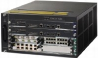
The Cisco 7604 Router is one of the smallest redundant routers to offer nx10GE performance with services. The Cisco 7604 Router, a four slot chassis, delivers performance in a compact five-rack unit (5 RU) form factor. It can be configured with a single supervisor engine and up to three line cards or for High Availability and redundancy, with dual supervisor engines and up to two line cards. The Cisco 7604 Router also supports redundant AC or DC power supplies for increased availability.
Ideal for Enterprise WAN aggregation or service provider environments, the Cisco 7604 offers one of the industry's leading array of interfaces (DS0 to OC-48/STM-16, FE, GE, 10GE) and services modules such as IPsec, Firewall, SSL VPN, IDS, and DDOS Protection. The Cisco 7604 also supports the Enhanced FlexWAN module, which offers Port Adapter investment protection for users looking to migrate their Cisco 7200 or 7500 Series.
This flexible router is ideal for addressing high-performance applications such as:
• High-end CPE
• Enterprise WAN Aggregation
• Lease Line
• IP/MPLS Provider Edge
• Metro Ethernet
Cisco 7604 Router Chassis Features:
• Five RU (8.75-inch) compact chassis, up to 9 chassis per 7-foot rack
• Four slots (2 Supervisor slots and 2 interface slots or 1 Supervisor slot with 3 interface slots)
• 1+1 route processor protection capability
• 1+1 power supply protection option, AC or DC
• Network Equipment Building Systems (NEBS) Level 3 compliance (post FCS)
• Single-side connection management for interface and power terminations
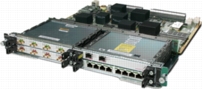
The Cisco 7600 Series SPA Interface Processor 400 (7600-SIP-400) Module enables high-performance, intelligent WAN and metropolitan-area network (MAN) services. Enterprises and service providers can leverage a wide variety of Cisco Shared Port Adapters (SPAs) for flexible, mixable WAN aggregation and connectivity options, and can benefit from the increased scalability, performance, and rich Quality of Service (QoS) features offered by the 7600-SIP-400 Module.
The 7600-SIP-400 Module accepts up to four shared port adapters commonly used with the Cisco 7304, Cisco 7600, Cisco 12000, and CRS-1 Series Routers as well as the Cisco Catalyst 6500 Series Switch. In addition, it offers increased performance and memory compared to the existing Optical Services Modules and FlexWAN modules. This innovative architecture is designed to deliver numerous media options and enable scalable, distributed, intelligent network services for current and next generation of applications.
7600-SIP-400 initially supports the following SPAs:
• SPA-2XOC3-POS-2-port OC-3c/STM-1 POS SPA
• SPA-4XOC3-POS-4-port OC-3c/STM-1 POS SPA
• SPA-1XOC12-POS-1-port OC-12c/STM-4 POS SPA
• SPA-2XOC3-ATM-2-port OC-3c/STM-1 ATM SPA
• SPA-4XOC3-ATM-4-port OC-3c/STM-1 ATM SPA
• SPA-1XOC12-ATM-1-port OC-12c/STM-4 ATM SPA
Figure 5. Cisco 7600 Series SPA Interface Processor-400
The Cisco 7600 SPA Interface Processor-200 (7600-SIP-200) Module enables high-performance, intelligent WAN services. Enterprises and service providers can take advantage of the many flavors of the Shared Port Adapters for their WAN aggregation and connectivity options, as well as the increased scalability, performance, and rich features offered by the 7600-SIP-200. Additionally, the 7600-SIP-200 provides feature parity with the Enhanced FlexWAN while offering twice the performance and increased scalability.
The 7600-SIP-200 Module accepts up to four shared port adapters commonly used with the Cisco 7304, Cisco 7600, Cisco 12000, and CRS-1 Series Routers as well as the Cisco Catalyst 6500 Series Switch. In addition, it offers increased performance and memory compared to the existing FlexWAN and Enhanced FlexWAN modules. This innovative architecture is designed to deliver numerous media options and enable scalable, distributed, intelligent network services for current and next generation of applications.
The rich QoS and low-speed WAN aggregation features of the 7600-SIP-200 enable users to:
• Classify and mark packets for QoS treatment within the network
• Guarantee bandwidth to business-critical applications
• Limit bandwidth to non-critical applications
• Avoid network congestion by dropping select low-priority packets
• Smooth out bursts and avoid packet discard in the network
• Compressed Real-Time Protocol (cRTP) to maximize bandwidth utilization
• Link fragmentation and interleaving (dLFI) to minimize jitter
• Multi-Link Point to Point Protocol (MLPPP), Multi-Link Frame Relay Protocol (MLFR), ATM VC Bundle, Frame Relay VC Bundle to bundle multiple low speed links
7600-SIP-200 initially supports the following SPAs:
• SPA-2XOC3-POS-2-port OC-3c/STM-1 POS SPA
• SPA-4XOC3-POS-4-port OC-3c/STM-1 POS SPA
• SPA-2XOC3-ATM-2-port OC-3c/STM-1 ATM SPA
• SPA-4XOC3-ATM-4-port OC-3c/STM-1 ATM SPA
• SPA-CH8TE1-8-port T1/E1 SPA, to DS0 SPA
• SPA-2XT3/E3-2-port T3/E3 SPA
• SPA-4XT3/E3-4-port T3/E3 SPA
• SPA-2XCT3/DS0-2-port CT3 SPA, to T1/E1 SPA
• SPA-4XCT3/DS0-4-port CT3 SPA, to T1/E1 SPA
Figure 6. Cisco 7600 Series SPA Interface Processor-200
The WS-C6504-E is a Cisco Catalyst 6500 Series 4-slot chassis with a redundant power supply option. It delivers up to 600W per slot, with a variable speed fan.
The PWR-2700-AC power supply provides 1319W at 110V and 2669W at 220V in the CISCO7606 chassis.
2700 Watt DC Power Supply for the Cisco 7606
The PWR-2700-DC power supply provides 1319W when connected with 1 DC-input and 2669W when connected with 2 DC-input in the CISCO7606 chassis.
2700 Watt AC Power Supply for the Cisco 7604
PWR-2700-AC/4 power supply provides 1319W at 110V and 2669W at 220V in CISCO7604 and WS-C6504-E chassis.
2700 Watt AC Power Supply for the Cisco 7604
PWR-2700-DC/4 power supply provides 1319W when connected with 1 DC-input and 2669W when connected with 2 DC-input in CISCO7604 or WS-C6504-E chasses.
Cisco 1-Port OC-12c/STM-4c ATM Shared Port Adaptor
Supported on Cisco 7600 Series SPA Interface Processor-400 in Release 12.2(18)SXE.
Cisco 2-Port OC-3c/STM-1c ATM Shared Port Adapter
Supported on Cisco 7600 Series SPA Interface Processor-400 and Cisco 7600 Series SPA Interface Processor-200 in Release 12.2(18)SXE.
Cisco 4-Port OC-3c/STM-1c ATM Shared Port Adapter
Supported on Cisco 7600 Series SPA Interface Processor-400 and Cisco 7600 Series SPA Interface Processor-200 in Release 12.2(18)SXE.
Cisco 1-Port OC-12c/STM-4c POS Shared Port Adapter
Supported on Cisco 7600 Series SPA Interface Processor-400 in Release 12.2(18)SXE.
Cisco 2-Port OC-3c/STM-1c POS Shared Port Adapter
Supported on Cisco 7600 Series SPA Interface Processor-400 and Cisco Series SPA Interface Processor-200 in Release 12.2(18)SXE.
Cisco 4-Port OC-3c/STM-1c POS Shared Port Adapter
Supported on Cisco 7600 Series SPA Interface Processor-400 and Cisco 7600 Series SPA Interface Processor-200 in Release 12.2(18)SXE.
Cisco 2-Port Clear Channel T3/E3 Shared Port Adapter
Supported on Cisco 7600 Series SPA Interface Processor-200 in Release 12.2(18)SXE.
Cisco 4-Port Clear Channel T3/E3 Shared Port Adapter
Supported on Cisco 7600 Series SPA Interface Processor-200 in Release 12.2(18)SXE.
Cisco 2-Port Channelized T3 (DS0) Shared Port Adapter
Supported on Cisco 7600 Series SPA Interface Processor-200 in Release 12.2(18)SXE.
Cisco 4-Port Channelized T3 (DS0) Shared Port Adapter
Supported on Cisco 7600 Series SPA Interface Processor-200 in Release 12.2(18)SXE.
Cisco 8-Port Channelized T1/E1 Shared Port Adapter
Supported on Cisco 7600 Series SPA Interface Processor-200 in Release 12.2(18)SXE.
1-Port Fast Ethernet Port Adapter
Adds support for 1-port Fast Ethernet Port Adapter (PA-FE-TX and PA-FE-FX) to the Enhanced FlexWAN Module.
2-Port Fast Ethernet Port Adapter
Adds support for 2-port Fast Ethernet Port Adapter (PA-2FE) to the Enhanced FlexWAN Module.
1-Port Packet over SONET OC3c/STM1 Port Adapter
Adds support for the 1-port OC3c/STM1 Port Adapter (PA-POS-1OC3) to the Enhanced FlexWAN and FlexWAN modules.
3.3 Cisco IOS Security
Dynamic Multipoint VPN
Dynamic Multipoint VPN (DMVPN) combines multipoint Generic Routing Encapsulation (mGRE) tunnels, IPsec encryption, and Next Hop Resolution Protocol (NHRP) routing to provide users a streamlined method of configuring large hub-to-spoke IPsec VPNs and enables dynamic discovery of tunnel endpoints. DMVPN eliminates the requirement for defining static crypto maps for site-to-site VPNs.
This feature relies on the following two Cisco technologies:
• NHRP: a client and server protocol where the hub is the server and the spokes are the clients. The hub maintains an NHRP database of the public interface addresses of the each spoke. Each spoke registers its real address when it boots and queries the NHRP database for real addresses of the destination spokes in order to build direct tunnels.
• mGRE Tunnel Interface: allows a single GRE interface to support multiple IPsec tunnels and simplifies the size and complexity of the configuration.
The topology shown in Figure 4 and the corresponding bullets explain how this feature works.
Figure 7. DMVPN
• Each spoke has a permanent IPsec tunnel to the hub, not to the other spokes within the network. Each spoke registers as clients of the NHRP server.
• When a spoke needs to send a packet to a destination (private) subnet on another spoke, it queries the NHRP server for the real (outside) address of the destination (target) spoke.
• After the originating spoke learns the peer address of the target spoke, it can initiate a dynamic IPsec tunnel to the target spoke.
• The spoke-to-spoke tunnel is built over the multipoint GRE interface.
• The spoke-to-spoke links are established on demand whenever there is traffic between the spokes. Thereafter, packets are able to bypass the hub and use the spoke-to-spoke tunnel.
Benefits
• Hub Router Configuration Reduction
– Currently, for each spoke router, there is a separate block of configuration lines on the hub router that define the crypto map characteristics, the crypto access list, and the GRE tunnel interface. This feature allows users to configure a single multipoint GRE tunnel interface, a single IPsec profile, and no crypto access lists on the hub router to handle all spoke routers. Thus, the size of the configuration on the hub router remains constant even if spoke routers are added to the network.
• Automatic IPsec Encryption Initiation
– GRE has the peer source and destination address configured or resolved with NHRP. Thus, this feature allows IPsec to be immediately triggered for the point-to-point GRE tunneling or when the GRE peer address is resolved via NHRP for the multipoint GRE tunnel.
• Support for Dynamically Addressed Spoke Routers
– When using point-to-point GRE and IPsec hub-and-spoke VPN networks, the physical interface IP address of the spoke routers must be known when configuring the hub router because IP address must be configured as the GRE tunnel destination address. This feature allows spoke routers to have dynamic physical interface IP addresses (common for cable and DSL connections). When the spoke router comes online, it will send registration packets to the hub router: Within these registration packets is the current physical interface IP address of this spoke.
• Simplifies the burden of headend management and thus reduces the total cost of ownership.
VPN Routing and Forwarding-Aware Dynamic Multipoint VPN
VPN Routing and Forwarding (VRF) Instance Integrated Dynamic Multipoint VPN (DMVPN) enables users to map site-to-site DMVPN IPsec sessions into Multiprotocol Label Switching (MPLS) VPNs. This allows service providers to extend their existing MPLS VPN service by mapping off-net sites (typically a branch office) to their respective VPNs. IPsec sessions are terminated on the DMVPN PE device and traffic is placed in VRFs for MPLS VPN connectivity. Specifically, work was done to extend the Next Hop Routing Protocol (NHRP) to look into the VRF Tables while building the database of spoke addresses in the hub.
Figure 8. VRF Aware DMVPN
Benefits
• DMVPNs can be used to extend the MPLS networks deployed by service providers to leverage the ease of configuration of hub and spokes, support for dynamically addressed CPEs and zero touch provisioning for adding new spokes into a DMVPN.
• DMVPN architecture can unite many spokes into a single multipoint GRE interface, removing the need for a distinct physical/logical interface for each spoke in a native IPsec installation.
It is not uncommon to situate a remote DMVPN spoke behind a NAT box, where a Port Address Translation (PAT) is enabled. When the DMVPN spokes need to send a packet to a destination (private) subnet behind another spoke, they query the Next Hop Resolution Protocol (NHRP) server for the real (outside) address of the destination spoke. The DMVPN hub maintains a NHRP database of the tunnel endpoints and the physical address of the spokes.
Figure 6 illustrates that it is typical for spokes in a DMVPN cloud to be given the same physical address by the NAT boxes sitting in front of them. As the spokes often times have no control over the addresses provided to them by the ISP, DMVPN was enhanced to work for spokes behind a NAT Box.
Figure 9. NAT Transparency Aware DMVPN
Benefits
Provides deployment flexibility when spoke routers are behind NAT boxes.
Dynamic Multipoint VPN (DMVPN) Spoke-to-Spoke Functionality allows dynamic on-demand direct spoke-to-spoke tunnels to be created between two DMVPN spoke CPEs without traversing the hub. This feature enables production-ready spoke-to-spoke functionality in single- and multi-hub environments in a DMVPN network. It also incorporates increased spoke-to-spoke resiliency and redundancy in multi-hub configurations.
Figure 10. DMVPN Spoke-to-Spoke Functionality
Benefits
• Direct spoke-to-spoke tunnels
– This functionality allows direct spoke-to-spoke tunnel creation between two branch offices without the traffic having to go through the hub. Spokes can take advantage of an internet connection directly available between them. This leads to reduced latency and jitter for spoke-to-spoke traffic and improved bandwidth utilization. DMVPN networks deliver a lower cost per MByte of Bandwidth than native IPsec networks because the spoke-to-spoke traffic is not restricted by hub bandwidth utilization and at the same time it does not add any additional overhead to the hub bandwidth utilization.
• Avoids dual encrypts and decrypts
– Native IPsec and IPsec + GRE networks are organized as hub and spoke networks. As a result, all spoke-to-spoke traffic traversing the hub and requiring a dual encrypt and decrypt for all traffic putting an additional burden on the hub CPU. DMVPN alleviates the problem by creating direct on-demand spoke-to-spoke tunnels.
• Smaller spoke CPEs can participate in a virtual on-demand full mesh
– DMVPN allows smaller spoke CPE to participate in a virtual on-demand full mesh. Creating and managing a full mesh is often not possible for smaller spoke CPE, which cannot handle more than a dozen IPsec tunnels. DMVPN allows the spokes to create tunnels to other spokes on demand and tear down the tunnels after use.
Cisco IOS Software headends that terminate SafeNet clients need to be able to support multiple groups of SafeNet clients using different wildcard preshared keys. Each key is placed in a keyring, which is bound to a specific interface address, so that the headend knows which key the client may be using.
Key Rollover for Certificate Renewal
Key Rollover for Certificate Renewal provides Policy Based Routing for IPv6 equivalent to IPv4.
Port Security with 4096 Secure MAC addresses
Increased system wide limit of 1024 secure MAC addresses to 4096 secure addresses.
Port Security with Sticky MAC Address
Port Security with Sticky MAC Address converts dynamically learned MAC addresses to configured addresses automatically.
Encapsulated Remote SPAN
Encapsulated Remote SPAN allows monitoring of traffic across Layer 3 networks.
SPAN Destination Port Permit List
SPAN Destination Port Permit List allows configuring a list of ports that are allowed to be SPAN destination ports. The intended use of this feature is as a safeguard to prevent the accidental misconfiguration of a port.
3.4 Cisco IOS Infrastructure
Server Load Balancing: Stateful Failover within Single Chassis
Server Load Balancing (SLB) for Stateful Switchover (SSO) enhances SLB by allowing it to failover to Redundant Supervisor in RPR+ configuration.
SLB intelligently load balances TCP/IP traffic across multiple servers. It appears as one "virtual" server to the requesting clients. All traffic is directed toward a virtual IP address (virtual server) via DNS. Those requests are distributed over a series of real IP addresses on servers (real servers).
SSO allows a redundant supervisor engine to start up in a fully-initialized state and synchronize with the persistent configuration and the running configuration of the active supervisor engine. It subsequently maintains the state on protocols, and all changes in hardware and software states for features that support stateful switchover are kept in sync. Consequently, it offers no zero interruption to Layer 2 sessions in a redundant supervisor engine configuration.
Combing with SSO, SLB can now preserve its state between primary and secondary RPs. As a result, it provides high availability and load balancing within a same chassis.
Figure 11. SLB Presents a Virtual Address and Load Balances the Traffic Across Multiple Servers
Benefits
Server Load Balancing: Stateful Failover within Single Chassis enables a cost-effective high availability and load balancing solution-allowing two service blades (ie: two MWAM) on a same chassis while maintaining high availability and load balancing.
Server Load Balancing (SLB) enhancement performing load-balancing decisions based on the input interface.
NetFlow Multiple Export Destinations
Export NetFlow records to two NetFlow Collectors.
NetFlow Bridged Flow Statistics
NetFlow Bridged Flow Statistics enables and disables bridged flow statistics on virtual LANs (VLANs).
Embedded Network Management Improvements
Key enhancements include Frame Relay 64-bit interface MIB support, UDI support, additional SONET/DS3 table MIB support, enhanced process/memory pool support for all line and jacket cards, and consistent alarming model across Optical Services Modules and SPA Interface Processors.
CNS Interactive Command Line Interface
CNS Interactive Command Line Interface (CLI) allows a non-interactive process to execute exec interactive configuration commands by storing the necessary input required by the CLI command and then providing it during the invocation of the command.
Clear Hardware Interface Counters
This feature provides the ability to clear hardware counters per interface. The cleared counter values can be viewed by using the new `delta' keyword in the `show counters interface' command.
Show Diagnostic Sanity
Parses through the configuration and evaluates certain system states to arrive at a set of warnings which could help the user set a more stable configuration.
Show top-n
Show top-n allows the user to collect counters over a specified interval and to display these counters in sorted order. For example, the user can collect the number of bytes or packets coming into all the ports in the system and then display the top 10 ports that have the most incoming traffic.
Unknown Unicast Flood Blocking
Provides a mechanism to block unknown unicast traffic on Layer 2 interfaces.
SCP Health Monitor
Provides debugging capabilities for the Enhanced FlexWAN.
RLB IMSI Sticky
Ability to bind all flows for the same user (identified by his IMSI address) to the same gateway with Exchange Director.
3.5 IP Addressing & Service
IPv6 Quality of Service
IPv6 Quality of Service (QoS) features supported for IPv6 environments include packet classification, queuing, traffic shaping, WRED, class-based packet marking, and policing of IPv6 packets. All of the QoS features are managed from the modular QoS command line interface (CLI). The modular QoS CLI (MQC) allows users to define traffic classes, create and configure traffic policies (policy maps), and then attach those traffic policies to interfaces.
The Cisco Catalyst 6500 Series and Cisco 7600 Series provide the QoS functionality for IPv6 packets. It is possible to classify IPv6 packets using the QoS TCAM and apply policing and marking decisions to the IPv6 traffic. The hardware support for scheduling, queuing and congestion control is implemented in the line card port ASICs. This accelerates IPv6 packet processing when QoS is enabled.
Benefits
• Enables IPv6 traffic engineering capability.
• Enables applications and/or service classification.
Dynamic Host Configuration Protocol version 6 Prefix Delegation
The current development of the IPv6 Internet and the IPv6 address allocation recommendation has led to the need for Internet service providers (ISPs) to offer relatively large address blocks to an increasing number of users. Every site with justification for more than one link is entitled to receive a /48 prefix allocation.
IPv6 enables simple, automatic host configuration. Conversely, there was nothing in the initial specification to automatically delegate a prefix to a router; so manual configuration was the only option.
Dynamic Host Configuration Protocol version 6 (DHCPv6) Prefix Delegation allows service providers to distribute relatively long-lived /48 prefixes to their users in a stateful fashion at the Service Provider border router. DHCPv6 performs a similar function to DHCPv4, and can also offer parameters such as DNS server and default domain names in a stateless manner.
Figure 12. DHCPv6 Prefix Delegration
Example of DHCPv6 Prefix Delegation Operation
1. A PPP link is established over a Layer 1 link between the CPE and the PE routers. The CPE router authenticates itself by username in the PPP authentication phase of the negotiation. PPP is not mandatory (Ethernet could also be used), but it does offer client authentication.
2. From the username contained in the PPP negotiation, a Radius request [RFC3162] is sent to the Service Provider Radius server. In the case of a valid username/password pair, the result of this request returns a /64 prefix to the PE. This prefix is then included in RA messages sent on the link connected to the CPE. The corresponding /64 prefix route is injected into the Service Provider routing system.
3. When the link between the CPE and the PE comes up, the CPE issues a DHCPv6 SOLICIT message to discover DHCPv6 servers on the link.
4. The PE router, acting as a DHCPv6 server, sends a DHCPv6 OFFER message.
5. The CPE router uses this piece of information to issue a DHCPv6 REQUEST message to acquire a /48 prefix from the PE router. Note that this sequence of messages may vary.
6. The PE responds with a DHCPv6 REPLY message, including the /48 prefix assigned to this particular CPE. This response may include Internet configuration items (i.e.: DNS servers' addresses, domain list). A /48 static route is automatically inserted in the PE routing table for the duration of the PPP connection. The DHCPv6 bindings (between CPE identifiers and prefixes) are stored locally on the PE.
7. The received prefix is used by the CPE as a "general prefix". From this /48 prefix, the CPE derives (by configuration) /64 prefixes to assign to connected interfaces.
8. The CPE interfaces configured as above start sending Router Advertisement messages on the corresponding links. Hosts on the links auto-configure their respective IPv6 interface addresses accordingly.
Stateless Dynamic Host Configuration Protocol version 6 for Domain Name Service
Dynamic Host Configuration Protocol version 6 (DHCPv6) Prefix Delegation is the key element of an easy IPv6 deployment. However, to have a fully functional IPv6 service, the hosts behind a router or a CPE need to be configured with Domain Name Service (DNS) server addresses and possibly other parameters (i.e.: domain lists). This configuration should be automated. Stateless DHCPv6 for DNS automates this configuration.
Stateless DHCPv6 for DNS enables routers to provide network parameters, such as DNS, in addition to IPv6 address, in a stateless manner. When the Router Advertisement messages sent by a router have the O-bit set indicating that other parameters can be retrieved in a stateless manner, hosts supporting DHCPv6 send a DHCPv6 INFORMATION-REQUEST message including the parameters it needs. If a DHCPv6 server is present on the link (it can be the CPE router), a DHCPv6 REPLY message with the requested parameters is received.
IP Unnumbered Support for Sub-Interfaces allows VLANs (sub-interfaces) of an Ethernet interface to "borrow" an IP address from another interface that has already configured with an IP address. This allows conserving IP addresses, especially, when the VLANs do not have many hosts or is literally a point-to-point connection.
For example, in Ethernet to the Home (ETTH) or DSL deployments, typically few hosts are connected to a concentrator on a VLAN segment and do not need an entire IP subnet to be assigned to the VLAN segment. Configuring an IP subnet for such sub-interfaces will result in inefficient use of the IP address space that belongs to a service provider. Implementing IP unnumbered support for Ethernet VLAN sub-interfaces will help conserve IP address space for such deployments.
Figure 14. IP Unnumbered Support for VLAN Interface
Benefits
• Savings in IPv4 address space because all ports can share the same subnet.
• Easy migration for DSL providers to Gigabit Ethernet uplinks and an IP core.
Dynamic Host Configuration Protocol (DHCP) Snooping provides security by filtering untrusted DHCP messages and by building and maintaining a DHCP snooping binding table. An untrusted message is one that is received from outside the network or firewall and that can cause traffic attacks within the network. For example, DHCP snooping can be used to differentiate an untrusted switch port connected to an end user from a trusted switch port connected to a DHCP server or another switch.
The DHCP snooping binding table contains the MAC address, IP address, lease time, binding type, VLAN number, and interface information that correspond to the local untrusted interfaces of a switch; it does not contain information regarding hosts interconnected with a trusted interface. An untrusted interface is an interface that is configured to receive messages from outside of the network or firewall. A trusted interface is one that is configured to receive only messages from within the network.
DHCP snooping acts like a firewall between untrusted hosts and DHCP servers. It also enables users to differentiate between untrusted interfaces connected to the end-user and trusted interfaces connected to the DHCP server or another switch.
DHCP snooping intercepts all DHCP messages between a client and a DHCP server, and tracks DHCP IP address assignment binding between the DHCP server and the client. It can filter the DHCP server response messages from an untrusted port, and perform per-port DHCP message rate limiting. DHCP snooping is typically used to prevent DHCP-related Denial of Service (DoS) attacks by identifying subscribers and filtering unauthorized network traffic. It can be enabled on a per-VLAN basis.
Benefits
• Enhances security by protecting a network from rogue DHCP servers and thus preventing a DHCP DoS attack.
• Eases troubleshooting by providing port information to DHCP IP address mapping.
Considerations
In order to enable DHCP snooping on a VLAN, DHCP snooping must be enabled on the switch.
Digital Optical Monitoring for GigaStack Gigabit Interface Converters
Certain transceivers support Digital Optical Monitoring in hardware. These transceivers periodically poll operating conditions such as temperature and power levels. This software enhancement allows the code to read and display these operating conditions. The reporting is done through both the CLI and the MIB. Threshold violations are supported as well: an alarm is generated if any of the values exceed their respective thresholds.
Dynamic Address Resolution Protocol (ARP) Inspection (DAI) is a security feature that validates ARP packets in a network. DAI allows a network administrator to intercept, log, and discard ARP packets with invalid MAC address to IP address bindings. This prevents man in the middle attacks that can be carried out by poisoning ARP caches with the help of ARP packets containing invalid IP to MAC address mappings.
To prevent ARP poisoning attacks, a switch must ensure that only valid ARP requests and responses are relayed. DAI prevents these attacks by intercepting all ARP requests and responses. Each of these intercepted packets is verified for valid MAC address to IP address bindings before the local ARP cache is updated or the packet is forwarded to the appropriate destination. Invalid ARP packets are dropped.
DAI determines the validity of an ARP packet based on valid MAC address to IP address bindings stored in a trusted database. This database is built at runtime by DHCP snooping, provided that it is enabled on the VLANs and on the switch. In addition, DAI can also validate ARP packets against user-configured ARP ACLs in order to handle hosts that use statically configured IP addresses.
DAI can also be configured to drop ARP packets when the IP addresses in the packet are invalid or when the MAC addresses in the body of the ARP packet do not match the addresses specified in the Ethernet header.
Figure 15. ARP Cache Poisoning Example
In Figure 9, Hosts HA, HB, and HC are connected to the switch on interfaces A, B and C, all of which are on the same subnet. Their IP and MAC addresses are shown in parentheses; for example, Host HA uses IP address IA and MAC address MA. When HA needs to communicate to HB at the IP Layer, HA broadcasts an ARP request for the MAC address associated with IB. As soon as HB receives the ARP request, the ARP cache on HB is populated with an ARP binding for a host with the IP address IA and a MAC address MA; for example, IP address IA is bound to MAC address MA. When HB responds, the ARP cache on HA is populated with a binding for a host with the IP address IB and a MAC address MB.
Host HC can "poison" the ARP caches of HA and HB by broadcasting forged ARP responses with bindings for a host with an IP address of IA (or IB) and a MAC address of MC. Hosts with poisoned ARP caches use the MAC address MC as the destination MAC address for traffic intended for IA or IB. This means that HC intercepts that traffic. Because HC knows the true MAC addresses associated with IA and IB, HC can forward the intercepted traffic to those hosts using the correct MAC address as the destination. HC has inserted itself into the traffic stream from HA to HB.
Benefits
Enhances security by reducing the risks associated with ARP poisoning and traffic hijacking.
Per-VLAN Load Balancing for Advanced QinQ Service Mapping
Allow multiple GE physical ports on multiple OSM-2+4GE-WAN modules to be logically grouped as a single link bundle. It would then be possible to assign any number of VLANs to this link bundle, rather than to specific physical ports within this link bundle. This system feature would then assign these VLANs on a round robin basis to physical ports within the link bundle.
Benefits
Enables link-building for redundancy and bandwidth management.
Multipoint Bridging (MPB) enables Layer 2 bridging across multiple ATM Virtual Circuits or multiple Frame Relay DLCIs and an Ethernet VLAN. It allows service providers to offer Ethernet-based multipoint services using their existing ATM and Frame networks. MPB is supported with RFC1483/2684 Bridged ATM VCs and RFC1490/2487 Bridged Frame Relay DLCIs. It supports a maximum of 4K VLANs, and a maximum of 60 VCs or DLCIs can be bridged to a VLAN.
MPB supports IEEE 802.1q tagged and untagged modes.
Figure 16. Multipoint Bridging
Hardware
• RFC1483 MPB is supported on all applicable Enhanced FlexWAN, 7600-SIP-200 and OSMs.
• RFC1490 MPB is supported on all applicable Enhanced FlexWAN, 7600-SIP-200 and OSMs.
Layer 2 Traceroute functionality traces the path from one node to another in a Layer 2 network.
Aggregated Differentiated Services Code Point/Precedence Values for WRED
This feature aggregates multiple Differentiated Services Code Point (DSCP)/Precedence values for a single min/max threshold and marks probability when specifying WRED parameters for the ATM SPAs on the 7600-SIP-400.
DE/CLP and EXP Mapping on Frame Relay/Asynchronous Transfer Mode over Multiprotocol Label Switching VirtualCircuits
AToM QoS feature where at imposition the PE router maps the FR DE or ATM CLP to MPLS EXP bit and at disposition the remote PE maps EXP back to DE/CLP.
Packet Classification Based on Layer 3 Packet-Length
Classifies packets based on Layer 3 packet length. The Layer 3 length can be configured as a range specified in bytes.
Percentage Based Policing
Allows policing to be configured in terms of percentage of the interface bandwidth, and thus, the same service-policy can be attached to different interface types regardless of their individual bandwidths. Release 12.2(18)SXE supports Percentage Based Policing on the WAN linecards.
Strict Priority Low Latency Queuing
Simple "policing" with drop action is needed to limit the traffic going into a strict priority queue in order to not starve other traffic queues. Prior to Strict Priority Low Latency Queuing (LLQ), Optical Services Modules supported only the `priority' command for LLQ. This new feature provides a policing function with priority.
Bandwidth Command in Hierarchical Quality of Service Parent Class
This feature enables configuration of `bandwidth' command in Hierarchical Quality of Service (QoS) parent class. Release 12.2(18)SXE supports the command on the OSM-2+4GE-WAN+.
Bandwidth Remaining
Bandwidth Remaining allows users to assign a weight to a queue to optimize scheduling of uncommitted bandwidth on an interface. Without this feature, the un-assigned bandwidth on an interface would be equally distributed amongst all defined queues. This feature enables the user to configure percentages for distribution of the un-assigned bandwidth to each of the queues.
Match VLAN
Match VLAN provides VLAN match/classification in MQC class-maps. This feature permits rate-limiting of ARP packets.
Egress IPv6 Multicast Replication with PFC3/DFC3
Egress IPv6 Multicast Replication allows IPv6 Layer 3 multicast replication to occur on egress-capable linecards.
IPv6 Multicast Route Processor Redundancy/Route Processor Redundancy+ Support on PFC3/DFC3
Route Processor Redundancy Plus (RPR+), the standby RP is fully initialized and configured. This feature allows RPR+ to dramatically shorten the switchover time if the active RP fails, or if a manual switchover is performed. Because both the startup configuration and running configuration are continually synced from the active to the standby RP, line cards are not reset during a switchover. The interfaces remain up during this transfer, so neighboring routers do not detect a link flap (ie: link does not go down and back up).
IDSM-2 Etherchannel Load Balancing
The IDSM-2 with 5.0 code will be recognized as an EtherChannel device by Supervisors in the Cisco Catalyst 6500 Series Switch chassis and allow them to participate with up to 8 total IDSM-2 devices in the same chassis.
3.6 Layer 2 and Layer 3 VPN
High-Level Data Link Control over Multiprotocol Label Switching
With Cisco AToM High-Level Data Link Control (HDLC) over Multiprotocol Label Switching (MPLS), an HDLC connection is emulated from one customer router to another across an MPLS backbone. This technology also allows transportation of Cisco HDLC frames across the packet networks, and functions in transparent mode.
The MPLS backbone network can be enabled to accept PPP or HDLC packets by configuring the PE routers at the both ends of the MPLS backbone. HDLC extends the usability of the MPLS backbone by enabling it to offer Layer 2 services in addition to already existing Layer 3 services.
Figure 17. HDLC over MPLS
Benefits
Enables MPLS service providers to offer Layer 2 services in which the Layer 2 encapsulation is HDLC.
Hardware
Requires FlexWAN, Enhanced FlexWAN, 7600-SIP-200, or OSM as the customer-facing interface and uplink to network core.
Point-to-Point Protocol over Multiprotocol Label Switching
With Cisco AToM, Point-to-Point Protocol (PPT) over Multiprotocol Label Switching (MPLS), users' PPP frames are encapsulated across an MPLS core. Using PPP over MPLS on POS links, service providers can create a "multiplexed" subinterface that can then be used to individually peer with other providers via a single POS connection. PPP over MPLS supports transparent pass through in which PPP sessions are between CE routers.
Figure 18. PPP over MPLS
The MPLS backbone network can be enabled to accept PPP or HDLC packets by configuring the PE routers at the both ends of the MPLS backbone. HDLC extends the usability of the MPLS backbone by enabling it to offer Layer 2 services in addition to already existing Layer 3 services.
Benefits
Enable MPLS service providers to offer layer 2 services in which the layer 2 encapsulation is HDLC.
Hardware
Requires FlexWAN, Enhanced FlexWAN, 7600-SIP-200 or OSM as the customer-facing interface and uplink to network core.
Hierarchical Quality of Service Support for Ethernet over Multiprotocol Label Switching Virtual Circuits
Hierarchical Quality of Service (HQoS) Support for Ethernet over Multiprotocol Label Switching (MPLS) enhances QoS control over MPLS networks by enabling hierarchical QoS on EoMPLS VCs. It provides following features on the egress side for EoMPLS VC:
• Matching based on EoMPLS input VLAN and input CoS
• Traffic Shaping/Class-Based Weighted Fair Queuing (CBWFQ)/Weighted Random Early Detection (WRED)/Fair Queue
• CoS to EXP Setting
• EXP to COS Setting
In certain deployment scenarios, users decide how to assign their traffic to the different subscribed classes of service by setting 802.1p or IP DSCP fields directly and want service provider edge routers to honor the Customer Diff-Serv settings. Customer applications are increasingly based on IP and Ethernet transport; thus, service provider edge routers that are cognizant of customer settings would gain competitive advantage. The feature supports these requirements ie: per-customer differentiated services using hierarchical QoS on point-to-point EoMPLS VC's.
Benefits
Provide service providers abilities to classify and policing user traffic over EoMPLS networks.
Hardware
Requires FlexWAN, Enhanced FlexWAN, or 7600-SIP-200 as the customer-facing interface.
Ethernet over Multiprotocol Label Switching per VLAN Quality of Service
Classify Ethernet over Multiprotocol Label Switching (EoMPLS) traffic on the core-facing egress interfaces. This allows the QoS to be done on the egress interfaces based on the ingress VLAN and other packet fields of the EoMPLS traffic. This way the ingress interface does not have to be capable of doing complicated QoS operations.
Benefits
Provide service providers the ability to classify and police user traffic over EoMPLS networks.
Multiprotocol Label Switching Label Switching Protocol Ping/Traceroute and AToM VCCV
As the number of Multiprotocol Label Switching (MPLS) deployments, as well as the number of traffic types they carry, increase, the ability of service providers to monitor label switched paths (LSPs) and quickly isolate MPLS forwarding problems is critical to their ability to offer services. The MPLS Embedded Management-LSP Ping/Traceroute and Any Transport over MPLS Virtual Circuit Connection Verification (AToM VCCV) feature helps them do this.
• MPLS Embedded Management-LSP Ping/Traceroute and AToM VCCV can detect when an LSP fails to deliver user traffic.
• MPLS LSP Ping can be used to test LSP connectivity for IPv4 Label Distribution Protocol (LDP) prefixes, traffic engineering (TE) Forwarding Equivalence Classes (FECs), and AToM FECs.
• MPLS LSP Traceroute can be used to trace the LSPs for IPv4 LDP prefixes and TE tunnel FECs.
• AToM VCCV enables the use of MPLS LSP Ping to test the Pseudo-Wire (PW) section of an AToM virtual circuit (VC).
Figure 20. MPLS LSP Traceroute Example-An MPLS LSP Traceroute Example with an LSP from LSR1 to LSR4
Benefits
• Extends diagnostic and troubleshooting capabilities to the MPLS network.
• Helps to diagnose the root cause when a forwarding failure occurs.
• Aids in the identification of inconsistencies between the IP and MPLS forwarding tables, inconsistencies in the MPLS control and data plane, and problems with the reply path.
Considerations
• MPLS LSP Traceroute cannot be used to trace the path taken by AToM packets. MPLS LSP Traceroute is not supported for AToM. (MPLS LSP Ping is supported for AToM.) However, MPLS LSP Traceroute can troubleshoot the Interior Gateway Protocol (IGP) LSP, which is used by AToM.
Allows users to configure ACLs to filter the label bindings which are accepted from peer LSRs.
3.7 IP Multicast
Multicast VPNs
Multicast VPNs (mVPNs) provide a scaleable architecture to enable multicast in an RFC2547 Layer 3 Multiprotocol Label Switching (MPLS) VPN environment.
Originally derived from tag switching, MPLS uses labels to combine the intelligence of routing with the high performance of switching. MPLS VPNs are a natural extension of MPLS and are often by service providers to offer VPN services over a shared infrastructure. MPLS VPNs operate based on label stacks.
Despite the advantage of label stacking and the ability to decouple routing from forwarding for unicast traffic, MPLS VPNs did not address how to handle multicast traffic. As a result, the only available solution for delivery of IP multicast video, voice, and data over a deployed Layer 3 MPLS VPN was to statically configure point-to-point GRE tunnels between Customer Edge (CE) routers. As the number of CE routers increased, the number of point-to-point GRE tunnels required to maintain a full mesh of CEs quickly became unmanageable. A more scalable solution was required.
Cisco IOS Multicast VPNs address the inherent scalability issues of using fully meshed point-to-point GRE tunnels by introducing the concept of Multicast Tunnel Interfaces (MTIs) and Multicast Distribution Trees (MDTs).
MTIs use GRE encapsulation; however they fundamentally differ from traditional point-to-point GRE tunnels in that they use multicast-rather than unicast-destination addresses. The multicast destination address used by a MTI is what allows a Provider Edge (PE) router to map Customer multicast traffic (C-packets) to Provider multicast traffic (P-packets).
Figure 21. Example of MTI Encapsulation
MVPN uses two types of MDTs in the MPLS core. Each serves a different purpose:
• Default-Multicast Distribution Tree (MDT): nailed tree used for maintaining PIM adjacencies between PE routers and carrying low-rate multicast traffic.
• Data-MDT: dynamic tree used for high-rate multicast traffic; unlike the Default-MDT, this tree is built only as needed between the source PE and PEs with interested receivers.
Figure 22. Example of Default-MDT
Figure 23. Example of Data-MDT
Benefits
• Allows service providers to configure and support multicast traffic in an MPLS VPN environment without using an overlay of fully-meshed point-to-point GRE tunnels between CE routers within the core for every customer VPN network.
• Maintains transparency between the customer and provider networks, which allows each to retain autonomy over its existing PIM domain using any of the multicast routing features available in Cisco IOS Software (ie: PIM Sparse Mode [PIM-SM], Bidirectional PIM [Bidir PIM], and Source Specific Multicast [SSM)])
• Does not impose any multicast-related configuration changes to customer-side networks.
• Only requires MVPN support and multicast in the core for Provider Edge (PE) routers.
• Provides optimal multicast forwarding in the core using PIM-SM or SSM.
• Provides multicast group aggregation in the core using Bidir-PIM.
MLD Snooping constrains IPv6 multicast traffic in a VLAN to receivers that have joined the multicast stream. It applies to Layer 2 VLANs, as well as VLANs with SVI (ie: routing enabled). It does not apply to pure Layer 3 routed interfaces.
In many network scenarios, users configure the network to use Generic Routing Encapsulation (GRE) tunnels to send Protocol Independent Multicast (PIM) and multicast traffic between routers. Typically, this occurs when the multicast source and receiver are separated by an IP cloud that is not configured for IP multicast routing. In such network scenarios, configuring a tunnel across an IP cloud with PIM enabled transports multicast packets toward the receiver.
Figure 24. Multicast over GRE
Benefits
Provide deployment flexibility to support multicast traffic over non-multicast capable or enabled networks.
Multicast over Virtual Routing and Forwarding Lite
Multi-Virtual Routing and Forwarding (VRF) Customer Edge (VRF-Lite) enables multiple VPN routing instances on Customer Edge devices. This is typically useful for service providers seeking to extend PE functionality to the customer edge.
Multicast over VRF Lite is an extension that supports Cisco IOS IP Multicast (PIM Sparse Mode, Bidirectional PIM, and Source Specific Multicast) across regular VRF Lite.
Figure 25. Multicast over VRF Lite
Figure 19 illustrates Multi-VRF deployment on a network that requires two separate VPNs for its operations: finance (teal) and engineering (red). This network is receiving a VPN service from Provider and has two sites connected to both VPNs.
A single physical interface using sub-interfaces is used to carry per-VPN unicast and multicast traffic between the Customer Edge and Provider Edge.
Note: Each VPN may also be assigned to its own physical interface between the Customer Edge and Provider Edge; however, this is a more expensive option.
Cisco IOS Source Specific Multicast (SSM) Mapping supports the transition of IP multicast solutions into SSM. It enables the deployment of SSM with hosts that are incapable of providing IGMP version 3 support in their TCP/IP host stack.
When the source is known in a multicast deployment, the simplicity of Protocol Independent Multicast-Source Specific Multicast (PIM-SSM) makes it the most appropriate multicast routing protocol to deploy. Entertainment solutions [ie: Ethernet to the Home (ETTH)] and financial deployments in which the application characteristics are one-to-many are two examples of multicast deployment that can typically benefit from
PIM-SSM.
PIM-SSM requires that a component on the host signal to the router regarding which group and source it wants to join. This can be IGMPv3, IGMPv3-lite, or URL Rendezvous Directory (URD).
When deploying SSM, however, it is not always feasible to expect these components to be on every host. SSM Mapping allows a provider or an enterprise to deploy PIM-SSM without relying on the hosts to possess these components (IGMPv3, IGMPv3-list, or URD). SSM Mapping enables Cisco routers to map a multicast group to a specific source.
With this new functionality, the router will look up the source associated with this group address and immediately initiate source-specific joins upon receipt of an Internet Group Management Protocol version 1 (IGMPv1) or IGMPv2 report. The SSM mapping database can be populated either statically or via the Domain Name Service (DNS).
Benefits
• Easy to install and manage: using source-to-group mappings, SSM Mapping provides the same ease of network installation and management as a pure SSM solution based on IGMPv3.
• Expedites SSM deployments: does not require every host to support IGMPv3, IGMPv3-lite or URD.
Considerations
• When SSM Mapping is enabled using "ip igmp ssm-map enable", but the source mapping list is empty for the group, issue the command "no ip igmp ssm-map query dns". This command will take in only statically configured SSM-mapped source entries. When searching for DNS-mapped dynamic entries, it takes an extremely long time to resolve. This may result in minor issues, such as failure to send IGMP Query packets.
• SSM enables reuse of group G for multiple different and independent applications. One application can send (S1, G) traffic while another independent application can send traffic from (S2, G). Because independent applications can send traffic and the SSM receiver host explicitly selects which source it wants to receive traffic from (S1 or S2) there is no conflict. The SSM Mapping feature does not share this benefit of full SSM (unlike URD or IGMPv3lite). Because SSM mapping takes a group G join from a host and identifies this group to indicate an application associated with one or more sources, it can only support one such application per group, G. Nevertheless, full SSM applications may still share the same group also used in SSM mapping. That is, SSM mapping is compatible with simultaneous URD, IGMPv3lite or IGMPv3 membership reports. Do not enable IGMPv3 on an interface if the receiver hosts that support IGMPv3 with applications do not support SSM directly and need to be supported by SSM mapping.
• As Explicit tracking is done only for v3 hosts and the switch is non-ssm-mapping aware, this can create group mode inconsistency between the Route Processor (RP) and Switch Processor (SP).
IPv6 Multicast provides support for intradomain multicast routing using Protocol Independent Multicast-Sparse Mode (PIM-SM). PIM-SM uses a pull model to deliver multicast traffic. Only network segments with active receivers, which explicitly request the data, will receive the traffic.
PIM-SM initially uses shared trees, so it requires the use of a Rendezvous Point (RP), which must be administratively configured in the network.
First-hop Designated Routers (FHDRs) with directly connected sources register with the RP, and subsequently forward data down the Shared Tree to all interested receivers. The edge routers learn about a particular source when they receive data packets that exceed a threshold on the shared tree then switchover to a new Shortest Path Tree (SPT). The edge router or any intermediate router towards the RP may also send prune messages up the shared tree as necessary while the new SPT is being built.
Benefits
• Efficient traffic forwarding: IPv6 PIM-SM uses an explicit-join model and builds distribution trees along only those branches of the network that require multicast.
• Efficient use of bandwidth: unlike PIM-DM, PIM-SM does not flood multicast traffic across all links to all routers in the network.
IPv6 multicast provides support for intradomain multicast routing using Source Specific Multicast (SSM). SSM eliminates the need from Protocol Independent Multicast (PIM)-SM Shared Trees and immediately creates Shortest Path Trees (SPTs) rooted at the source.
IPv6 SSM can accomplish this for two reasons:
1. Multicast Listener Discovery (MLD) v2 can specify the source in its request to the local router.
2. Sources must inform receivers of their existence via a method other than registering with the network.
Figure 26. IPv6 Source Specific Multicast
Benefits
• Easy to install and manage: IPv6 SSM provides the same ease of network installation and management as a pure IPv4 SSM solution based on IGMPv3.
• IP Multicast Address Management not required: eliminates the need for IP Multicast address management.
• IP Multicast Rendezvous Point management not required: Rendezvous Points are not required because Shared Trees are not used.
• Denial of Service attacks from unwanted sources inhibited: because the SSM feature only builds SPTs for known sources, any other sources in the network are ignored.
Multicast Listener Discovery Version 1 and Version 2
Multicast Listener Discovery (MLD) version 1 performs the functions and is derived from Internet Group Management Protocol (IGMP) v2, while MLDv2 is equivalent to IGMPv3 and requires interoperation with IPv6 SSM. Unlike IGMP in IPv4, MLD uses ICMPv6 to carry its messages. All MLD messages are local to the link with a Hop Limit of 1 with the Router Alert option enabled.
There are three types of MLD messages:
1. Query (Type = decimal 130)
General and Group Specific
In a Query message, the Multicast Address field is set to zero when it sends a General Query, which learns which Multicast addresses have listeners on an attached link. In a Group-Specific or Multicast-Address-Specific Query, the address field is set to a specific IPv6 Multicast address. This query discovers whether a particular Multicast address has any listeners on an attached link.
2. Report (Type = decimal 131)
In a Report message, the Multicast Address field matches that of the specific IPv6 Multicast address to which the receiver is listening.
3. Done (Type = decimal 132)
In a Done message, the Multicast Address field matches that of the specific IPv6 Multicast address to which the receiver is ceasing to listen.
Benefits
Provides the same functionality as IGMPv2 and v3, for IPv6 multicast networks.
IPv6 Multicast Explicit Host Tracking allows a router to track the behavior of hosts within an IPv6 network and provides a fast leave mechanism that can be used with Multicast Listener Discovery (MLD) version 2 host reports.
Benefits
Fast detection of IPv6 multicast hosts that leave a multicast group.
Source Specific Multicast Mapping for Multicast Listener Discovery Version 1
IPv6 Multicast does not use the Internet Group Management Protocol (IGMP) when a host signals a router with its desire to receive data from a specific group. IPv6 uses a new protocol called Multicast Lister Discovery (MLD). MLD is a sub protocol of ICMP in IPv6.
There are two versions of MLD today:
• MLDv1: similar to IGMPv2
• MLDv2: similar to IGMPv3; used with IPv6 Source Specific Multicast (SSM)
Since MLDv1 is unable to send source-specific joins, it will not work with SSM natively.
However, SSM Mapping for MLD v1 overcomes this limitation and facilitates the deployment of IPv6 SSM with hosts that are incapable of providing MLD version 2 messages.
SSM Mapping for MLD v1 works by mapping group to source pairs either locally on the router or via a Domain Name Service (DNS) server. When an MLD v1 report is received for a particular group, the feature associates the group to a source in its SSM mapping table. This triggers source-specific joins.
SSM Mapping for MLDv1 will support both static and dynamic DNS mapping for MLD v1 receivers.
Benefits
Flexible deployment: allows deployment of IPv6 SSM with hosts that are incapable of providing MLD version 2 messages.
Boot Strap Router (BSR) is one of the mechanisms by which an IPv6 Protocol Independent Multicast (PIM) router learns the set of Group-to-RP mappings required for IPv6 PIM-Sparse Mode (PIM-SM) and Bidirectional PIM (Bidir-PIM) to function. The mechanism is dynamic, largely self-configuring, and robust to router failure. This feature adds the BSR support for IPv6 PIM SM.
Benefits
• Minimizes configuration requirements. Not required on all routers in a multicast enabled network.
• Provides an alternative for interoperating with systems that do not understand or support Auto-Rendezvous Point (Auto-RP), another method of dynamically advertising Group-to-RP mappings.
Considerations
The ability to configure a candidate-RP to map Bidirectional multicast groups is not available yet.
The convergence of business-critical applications onto a common IP infrastructure in enterprise and service provider networks is becoming more common. Given the criticality of the data, these networks are typically constructed with a high degree of redundancy. While such redundancy is desirable, its effectiveness is dependant upon the ability of individual network devices to quickly detect failures and reroute traffic to an alternate path.
This detection is usually accomplished via hardware detection mechanisms. However, the signals from these mechanisms are not always conveyed directly to the upper protocol layers. When the hardware mechanisms do not exist (ie: Ethernet) or when the signaling does not reach the upper protocol layers, the protocols must rely on their much slower strategies to detect failures. The detection times in existing protocols are typically greater than one second, and sometimes much longer. For some applications, this is too long to be useful.
Bi-directional Forwarding Detection (BFD) provides rapid failure detection times between forwarding engines, while maintaining low overhead. It also provides a single, standardized method of link/device/protocol failure detection at any protocol layer and over any media.
Figure 27. Bi-Directional Forwarding Detection
Router A detects Router B failure within 150msec after missing 3 BFD control packets from the Router B. The BFD on the Router A, then, informs its clients (such as OSPF routing protocol process) about the failure.
Benefits
• Fast network convergence.
• Media independent link failure detection.
• Easier network profiling and planning.
Considerations
• The first phase release of the BFD supports OSPF, ISIS, and EIGRP. BGP and other protocols are not supported in the first phase.
• BFD is not supported over OSPF virtual links or sham links, as the current specification for BFD usage on IP links limits BFD to one-hop adjacencies.
• BFD will consume some CPU resources, although many optimizations have been made to ensure the CPU usage is minimal.
BGP Multipath Load Sharing for Both External BGP and Internal BGP in a Multiprotocol Label Switching VPN
Border Gateway Protocol (BGP) Multipath Load Sharing for eBGP and iBGP in a Multiprotocol Label Switching (MPLS) VPN allows users to configure multipath load balancing with both external BGP (eBGP) and internal BGP (iBGP) paths in BGP networks that are configured to use MPLS VPNs. This feature provides improved load balancing deployment and service offering capabilities and is useful for multi-homed autonomous systems and Provider Edge (PE) routers that import both eBGP and iBGP paths from multihomed and stub networks. In MPLS/VPN networks, in a vrf which has paths imported from a eBGP and iBGP path, one can use both eBGP and iBGP path as multipaths and install them in the RIB.
The multipaths are used by Cisco Express Forwarding to perform load balancing, which can be performed on a per-packet or per-source or destination pair basis. The BGP Multipath Load Sharing for Both eBGP and iBGP in an MPLS VPN feature performs unequal cost load balancing by default by selecting BGP paths that do not have an equal cost of the Interior Gateway Protocol (IGP). In order to enable the BGP Multipath Load Sharing for both eBGP and iBGP in an MPLS VPN feature, configure the router with MPLS VPNs that contain VPN routing and forwarding instances (VRFs) that import both eBGP and iBGP paths. The number of multipaths can be configured separately for each VRF.
Figure 28. A Service Provider BGP MPLS Network
Figure 25 shows a service provider BGP MPLS network that connects two remote networks to PE router 1 and PE router 2, which are both configured for VPNv4 unicast iBGP peering. Network 2 is a multihomed network that is connected to PE router 1 and PE router 2. Network 2 also has extranet VPN services configured with Network 1. Both Network 1 and Network 2 are configured for eBGP peering with the PE routers.
PE router 1 can be configured with the BGP Multipath Load Sharing for Both eBGP and iBGP in an MPLS VPN feature so that both iBGP and eBGP paths can be selected as multipaths and imported into the VRF of Network 1. The multipaths will be used by Cisco Express Forwarding to perform load balancing. IP traffic that is sent from Network 2 to PE router 1 and PE router 2 will be sent across the eBGP paths as IP traffic. IP traffic that is sent across the iBGP path will be sent as MPLS traffic, and MPLS traffic that is sent across an eBGP path will be sent as IP traffic. Any prefix that is advertised from Network 2 will be received by PE router 1 through route distinguisher (RD) 21 and RD 22.The advertisement through RD 21 will be carried in IP packets, and the advertisement through RD 22 will be carried in MPLS packets. Both paths can be selected as multipaths for VRF1 and inserted into the VRF1 RIB.
Benefits
BGP Multipath Load Sharing for Both eBGP and iBGP in an MPLS VPN allows multihomed autonomous systems and PE routers to be configured to distribute traffic across both eBGP and iBGP paths.
Considerations
• Route Reflector Limitation
– With multiple iBGP paths installed in a routing table, a route reflector will advertise only one of the paths (one next hop). If a router is behind a route reflector, all routers that are connected to multihomed sites will not be advertised unless separate VRFs with different RDs are configured for each VRF.
• Memory Consumption Restriction
– Each IP routing table entry for a BGP prefix that has multiple iBGP paths uses additional memory. It is recommended not to use this feature on a router with a low amount of available memory and especially when the router is carrying a full Internet routing table.
Allows BGP to establish a session only if the TTL packet field matches what is expected from the neighbor.
EIGRP Multiprotcol Label Switching VPN PE-CE Site of Origin
In a MPLS VPN EIGRP PE-CE scenario, EIGRP Site of Origin is required to support topologies such as customer sites that have both backdoor links and MPLS VPN links.
IS-IS Support for Priority-Driven IP Prefix RIB Installation
Allows users to achieve faster convergence by tagging high-priority IP prefixes for faster processing and installation in the global routing table.
OSPF Link State Database Overload Protection
Prevents CPU and memory resource exhaustion due to excess link-state advertisements (LSAs) received for a given Open Shortest Path First (OSPF) process.