Feedback
Table Of Contents
Positioning Access Points and Antennas for
Site SurveysAntennas and Antenna Positioning
Positioning Access Points and Antennas for
Site Surveys
When you perform a site survey, it is important to position wireless equipment for optimal coverage. This chapter describes best practices for positioning access points and antennas.
Access Point Positioning
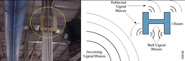
In industrial environments such as warehouses, a common installation point for access points is on girders or I-beams. However, an I-beam reflects both received packets and transmitted packets, resulting in poor signal quality because of nulls and high-strength mulitpath signals. Figure 5-1 shows the I-beam installation and the resulting signal propagation. The null is created by the crossing of signal waves shown in the scattered waveforms diagram. The multipath is shown as the multiple waves in the signal.
Figure 5-1 Access Point Installed on I-Beam
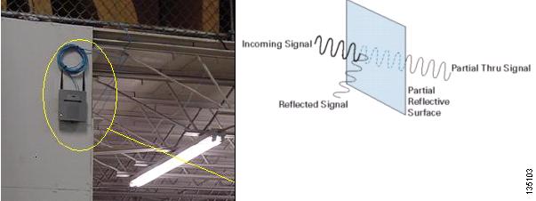
The access point in Figure 5-2 provides better coverage because the reflected signal produces fewer nulls and less multipath than the I-beam placement. However, because there is only one floor in this industrial building, there is no need for the antennas to be above the access point. The signal could be improved by inverting the access point so that the antennas point to the ground.
Figure 5-2 Access Point Installed on a Wall
Antennas and Antenna Positioning
Interference and multipath cause the transmitted signal to fluctuate. Interference increases the required signal-to-noise ratio for a particular data rate. The packet retry count goes up in areas where interference or multipath are high. Changing the type and location of the antenna can reduce multipath interference. Antenna gain adds to the system gain and improves the signal-to-noise requirement.
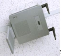
Figure 5-3 shows proper positioning of the antennas on a dual-radio access point mounted on a suspended ceiling. Both the removable antennas and the paddle antenna are pointed down at the floor.
Figure 5-3 Access Point Installed on a Suspended Ceiling
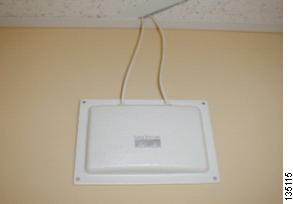
Figure 5-4 shows a patch antenna mounted on a wall. The antenna cables are routed above the suspended ceiling and are attached to a hidden access point.
Figure 5-4 Patch Antenna Mounted on a Wall
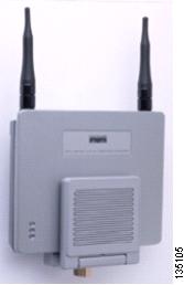
Figure 5-5 shows a dual-radio access point mounted on a wall. The removable antennas are pointed up, and the paddle antenna is folded against the body of the access point.
Figure 5-5 Access Point Mounted on a Wall
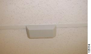
Figure 5-6 shows a patch antenna mounted on a suspended ceiling. The cables are hidden and are routed above the ceiling to the access point.
Figure 5-6 Patch Antenna Mounted on a Suspended Ceiling