-
CT5760 Controller Deployment Guide
-
Preface
-
Product Overview
-
Supported Features
-
CT5760 Centralized Configuration Example
-
Mobility Architecture
-
Mobility Design and Configuration
-
Bring Your Own Device Security Configuration
-
Secure WLAN Configuration
-
802.11ac Support on WLC5760 and Catalyst 3850
-
Radio Resource Management Configuration
-
CleanAir
-
High Availability
-
Interface Group
-
Multicast Configuration
-
Installing and Upgrading Software Image on a CT5760
-
Adding WLC to Prime
-
Application Visibility and Flexible Netflow
-
Service Discovery Gateway (mDNS Gateway)
-
QoS Configuration
-
 Feedback
Table Of Contents
CT5760 Centralized Configuration Example
CT5760 Controller Configuration Example using CLI
Enable the CT5760 Controller Web GUI
Enabling WEB GUI on both the 5760 and 3850 Platforms
GUI Access for CT5760/3850 Example
Add Management and Client Interface
Wireless Management Interface Configuration on CT5760
DHCP Snooping and Trust Configuration on CT5760
Wireless WebAuth and Guest Anchor Solutions
Configure Parameter-Map Section in Global Configuration
Configure Customized WebAuth Tar Packages
Configure Parameter Map with Custom Pages
Configure Parameter Map with Type Consent and Email Options
Configure Local WebAuth Authentication
Configure External Radius for WebAuth
Configure HTTP Server in Global Configuration
Other Configurations to be Checked or Enabled
Enable IPv6 on Interface - CT5760
CT5760 Centralized Configuration Example
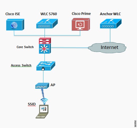
Network Topology
The diagram in Figure 3-1 shows the network topology with only the Unified Access CT5760 controller in a centralized deployment.
Figure 3-1 Network Topology Centralized Configuration
VLANs and IP Addresses
CT5760 Controller Configuration Example using CLI
Before you start the controller configuration, ensure that there is complete connectivity between all of the switches in the configuration above.
Console Connection
Before you can configure the switch or controller for basic operations, you must connect it to a PC that uses a VT-100 terminal emulator (such as HyperTerminal, ProComm, or Putty).
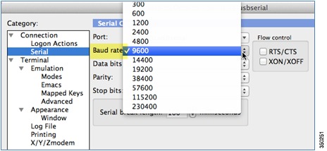
The controller has both EIA/TIA-232 asynchronous (RJ-45) and USB 5-pin mini Type B, 2.0 compliant serial console ports. The default parameters for the console ports are 9600 baud, eight data bits, one stop bit, and no parity. The console ports do not support hardware flow control. Choose the serial baud rate of 9600; if you have issues, try a baud rate of 115200.Figure 3-2 shows an example of a Mac Secure CRT; use similar for PC/Windows Putty, and so on.
Figure 3-2 Mac Secure CRT Example
Startup Wizard
Before you launch the startup wizard, have your IP addresses and VLANs information available. Start without the wizard/initial configuration dialog (check the initial configuration).
% Please answer 'yes' or 'no'.
Would you like to enter the initial configuration dialog? [yes/no]:no
Would you like to terminate autoinstall?[yes]:
Controller>
Press RETURN to get started!
Start with the wizard/initial configuration dialog (check the initial config).
Enable secret warning
----------------------------------
In order to access the device manager, an enable secret is required
If you enter the initial configuration dialog, you will be prompted for the enable
secret
If you choose not to enter the initial configuration dialog, or if you exit setup
without setting the enable secret,
please set an enable secret using the following CLI in configuration mode-
enable secret 0 <cleartext password>
----------------------------------
Would you like to enter the initial configuration dialog? [yes/no]:yes
At any point you may enter a question mark '?' for help. Use ctrl-c to abort configuration dialog at any prompt. Default settings are in square brackets '[]'.
Basic management setup configures only enough connectivity for management of the system, extended setup will ask you to configure each interface on the system
Would you like to enter basic management setup? [yes/no]:yes
Configuring global parameters:
Enter host name [Controller]:CT5760-Controller
The enable secret is a password used to protect access to privileged EXEC and configuration modes. This password, after entered, becomes encrypted in the configuration.
Enter enable secret:Cisco123
The enable password is used when you do not specify an enable secret password, with some older software versions, and some boot images.
Enter enable password:Cisco123
The virtual terminal password is used to protect access to the router over a network interface. Enter virtual terminal password:Cisco123
Configure a NTP server now? [yes]:yes
Enter ntp server address :10.10.200.1
Enter a polling interval between 16 and 131072 secs which is power of2:16
Do you want to configure wireless network? [no]:yes
Enter mobility group name:New-Mobility
Enter the country code[US]:US
Configure SNMP Network Management? [no]:no
Current interface summary
Any interface listed with OK? value "NO" does not have a valid configuration
Enter interface name used to connect to the management network from the above interface summary:GigabitEthernet0/0[service port)
Configuring interface GigabitEthernet0/0: Configure IP on this interface? [no]:yes
IP address for this interface:192.168.2.50
Subnet mask for this interface [255.255.0.0] :255.255.255.0Wireless management interface needs to be configured at startup
It needs to be mapped to an SVI that is not Vlan 1 (default)
Enter VLAN No for wireless management interface: 200
Enter IP address: 10.10.200.5
Enter IP address mask:: 255.255.255.0
[0] Go to the IOS command prompt without saving this config.
[1] Return back to the setup without saving this config.
[2] Save this configuration to nvram and exit.
Enter your selection [2]:2
Press RETURN to get started!Version
#show versionIOS XE 3.X (3.2.0SE at FCS ) is the official version for 3850/5760 & should be the only version number used when referring to 3850/5760.
#show version runningWill show the WCM and IOSd versions
#show ap name apname config generalWill show AP version, which will be 15.X at FCS.
Date and Time Configuration
clock set hh:mm:ss day month year
Enable the CT5760 Controller Web GUI
Supported Browser Version
Below is a list of supported browser versions:
•
Chrome - Ver. 26.x
•
•
Enabling WEB GUI on both the 5760 and 3850 Platforms
Both the Cat3850 and CT5760 currently ship with the first release labeled as 3.2.01. If you have an existing CAT3850/CT5760 and want to use GUI to Configure/Monitor your wireless network, please follow the steps below:
1.
Note
2.
3.
Controller(config)#username admin privilege 15 password Cisco123.Or you can configure it to use credentials using an authentication server. Make sure the user has privilege 15 access level.4.
5.
Note
GUI Access for CT5760/3850 Example
Complete these steps:
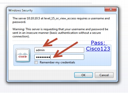
Step 1
For example:
https://10.10.10.5
username: admin
Password: Cisco123
Note
Controller(config)#username admin privilege 15 password Cisco123.This is an example and not the default username and password.
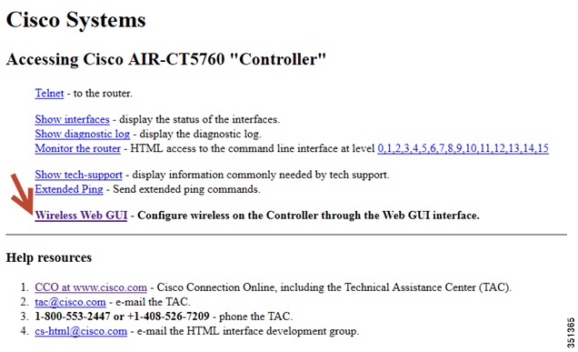
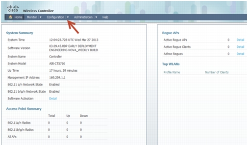
Once you login, you will be directed to the following page:
Step 2
Note
Basic Configuration
This section shows the configuration options from the console of the CT5760 for the following:
•
•
Add Management and Client Interface
interface Vlan200
description "Management VLAN"
ip address 10.10.200.5 255.255.255.0
no shut
interface Vlan100
description "Client VLAN"
no shut
default-gateway 10.10.200.1Wireless Management Interface Configuration on CT5760
Wireless management interface has been configured as part of the Startup Wizard section above. If you have not configured it through the Startup Wizard, you need to configure it by issuing the following command:
Controller# wireless management interface Vlan200This will enable the AP to join the controller.
DHCP Snooping and Trust Configuration on CT5760
ip dhcp snooping vlan 100, 200
ip dhcp snooping wireless bootp-broadcast enable
ip dhcp snooping
interface TenGigabitEthernet1/0/1
description Connection to Core Switch
switchport trunk allowed vlan 100, 200
switchport mode trunk
ip dhcp relay information trusted ip dhcp snooping trust
interface Vlan100
description Client Vlan
ip dhcp relay information trustedDHCP snooping is required for the following functionality:
1.
2.
3.
4.
5.
WLAN Configuration
Configure a WLAN and assign a client VLAN. Use WPA/PSK for security, and the passkey is cisco123.
wlan corporate 1 corporate band-select
client vlan 100
no security wpa akm dot1x
security wpa akm psk set-key ascii 0 cisco123
no shutdownEnter this command to allow management over wireless.
wireless mgmt-via-wireless <cr>AP Joins
Connect an AP to any port configured with Vlan 200 on the L2 switch. Wait until it joins and enter command:
show ap summary
show ap summary
Number of APs: 1
Global AP User Name: Not configured
Global AP Dot1x User Name: Not configured
AP Name / AP Model / Ethernet MAC / Radio MAC / State
---------------------------------------------------------------------------------
AP44d3.ca42.321a / 3602I / 44d3.ca42.321a / 64d9.8942.4090 / RegisteredConnect a wireless client to the corporate SSID with the WPA key 'cisco123'. On the controller, you might see the following successful authorization for new client association.
Show wireless client summary from controller to confirm wireless clients.
Security Configuration
This section shows the configuration options from the console of the CT5760:
•
•
•
Form CT5760 console (telnet/serial) - Configure AAA
aaa new-model
!
aaa group server radius Cisco
server 10.10.200.60
!
aaa authentication login no_auth none
aaa authentication dot1x default group radius
aaa authentication dot1x Cisco_dot1x group Cisco
aaa authorization network default group Cisco
aaa accounting network default start-stop group Cisco
dot1x system-auth-control
!
aaa server radius dynamic-author
auth-type any
!
radius-server attribute 6 on-for-login-auth
radius-server dead-criteria time 10 tries 3
radius-server deadtime 3
radius-server vsa send accounting
radius-server vsa send authentication
!
radius server Cisco
address ipv4 10.10.200.60 auth-port 1812 acct-port 1813
key secretThis command creates the WLAN with 802.1x security.
wlan corporate1x 2 corporate1x
accounting-list Cisco
client vlan 100
security dot1x authentication-list Cisco
session-timeout 600
no shutdownConnect wireless client to corporate-1x with the following credentials:
Username = cisco ; Password = Cisco123
Controller#show wireless client summaryWireless WebAuth and Guest Anchor Solutions
The following sections show a WebAuthentication (WebAuth) configuration and Guest Anchor examples on the CT5760.
Note
release=3.2.2&relind=AVAILABLE&rellifecycle=&reltype=latest .The readme file has all the GUI and CLI configuration for webauth.
Configure Parameter-Map Section in Global Configuration
The parameter map connection configuration mode commands allow you to define a connection- type parameter map. After you create the connection parameter map, you can configure TCP, IP, and other settings for the map.
! First section is to define our global values and the internal Virtual Address.
! This should be common across all WCM nodes.
PARAMETER-MAP TYPE WEBAUTH GLOBAL?
VIRTUAL-IP IPV4 192.0.2.1
PARAMETER-MAP TYPE WEBAUTH WEBPARALOCAL?
TYPE WEBAUTH?
BANNER TEXT ^C WEBAUTHX^C
REDIRECT ON-SUCCESS HTTP://9.12.128.50/WEBAUTH/LOGINSUCCESS.HTML
REDIRECT PORTAL IPV4 9.12.128.50Configure Customized WebAuth Tar Packages
Transfer each file to flash:
copy tftp://10.1.10.100/WebAuth/webauth/ webauth_consent.html flash:webauth_consent.html
copy tftp://10.1.10.100/WebAuth/ webauth_success.html flash: webauth_success.html
copy tftp://10.1.10.100/WebAuth/ webauth_failure.html flash: webauth_failure.html
copy tftp://10.1.10.100/WebAuth/ webauth_expired.html flash: webauth_expired.html
Note
•
•
<img src="http://[wireless management ip]/flash:[name of the file]">Configure Parameter Map with Custom Pages
parameter-map type webauth webparalocal
type webauth
custom-page login device flash:webauth_consent.html
custom-page success device flash:webauth_success.html
custom-page failure device flash: webauth_failure.html
custom-page login expired device flash:webauth_expired.htmlConfigure Parameter Map with Type Consent and Email Options
parameter-map type webauth webparalocal
type consent
consent email
custom-page login device flash:webauth_consent.html
custom-page success device flash:webauth_success.html
custom-page failure device flash:webauth_failure.html
custom-page login expired device flash:webauth_expired.htmlConfigure Local WebAuth Authentication
username guest password guest123
aaa new model
dot1x system-auth-control
aaa authentication login EXT_AUTH local
aaa authorization network EXT_AUTH local
aaa authorization network default local
or
aaa authentication login default local
aaa authorization network default localConfigure External Radius for WebAuth
aaa new model
dot1x system-auth-control
aaa server radius dynamic-author ?
client 10.10.200.60 server-key cisco ?server-key cisco ?
auth-type any
radius server cisco
address ipv4 10.10.200.60 auth-port 1812 acct-port 1813
key cisco
aaa group server radius cisco server name cisco
aaa authentication login EXT_AUTH group cisco
or
aaa authentication login default group ciscoConfigure WLAN with WebAuth
wlan Guest-WbAuth 3 Guest-WbAuth
client vlan 100
mobility anchor 192.168.5.1
no security wpa
no security wpa akm dot1x
no security wpa wpa2
no security wpa wpa2 ciphers aes
security web-auth
security web-auth authentication-list EXT_AUTH
security web-auth parameter-map webparalocal
no shutdownConfigure HTTP Server in Global Configuration
!--- These are needed to enable Web Services in the Cisco IOS® software.
ip http server
ip http secure-server
ip http active-session-modules noneOther Configurations to be Checked or Enabled
!--- These are some global housekeeping Cisco IOS® software commands:
ip device tracking
ip dhcp snoopingSNMP Configuration
From the CT5760 console, configure the SNMP strings.
snmp---server community public ro
snmp---server community private rw
IPv6 Configuration
IPv6 is supported on the data path. Wireless clients will be able to get an IPv6 address.
Enable IPv6 Snooping - CT5760
There are slight differences in configurations on a CT5760 when configuring IPv6. To enable IPv6 on a CT5760, the following step must be completed.
ipv6 nd raguard attach-policy testgaurd
Trusted-port
Device-role router
interface TenGigabitEthernet1/0/1
description Uplink to Core Switch
switchport trunk native vlan 200
switchport mode trunk
ipv6 nd raguard attach-policy testgaurd
ip dhcp snooping trustEnable IPv6 on Interface - CT5760
Based on interfaces that need IPv6 configurations and the type of address needed, respective configurations are enabled as follows. IPv6 configurations are enabled on VLAN200.
vlan configuration 100 200
ipv6 nd suppress
ipv6 snooping
interface Vlan100
descriptionClient VLAN
ip address 10.10.100.5 255.255.255.0
ip helper-address 10.10.100.1 2001:DB8:0:10::1/64
ipv6 address FEC0:20:21::1/64
ipv6 enable