Feedback
Contents
- Scope, Objectives, and Expectations
- The New AP 1532
- Getting Started with the AP 1532
- Flexible Antenna-Port Configuration
- Daisy Chaining with AP 1532
- Enabling Daisy Chaining using the WLC GUI
- Enabling Daisy Chaining using the WLC CLI
- Enabling Daisy Chaining Using the AP CLI
- Preferred Parent
- Bridge Group Name
- Deployment Modes
- Autonomous Software
- Range and Capacity Calculator
- Design and Planning with the 1532 Access Point
- Troubleshooting
Scope, Objectives, and Expectations
This Deployment Guide will be the first introduction to the AP 1532 platform. This guide will cover the following topics in depth:The following topics are covered under this chapter:
- The New AP 1532
- Getting Started with the AP 1532
- Flexible Antenna-Port Configuration
- Daisy Chaining with AP 1532
- Preferred Parent
- Bridge Group Name
- Deployment Modes
- Autonomous Software
- Range and Capacity Calculator
- Design and Planning with the 1532 Access Point
- Troubleshooting
The New AP 1532
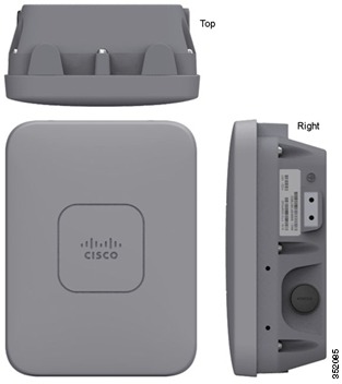
The AP 1532 series is an ultra low-profile outdoor access point. This AP has two models, an internal antenna model and an external antenna model.
AP 1532E
The 1532E has the following features:Getting Started with the AP 1532
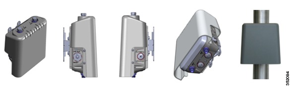
The AP 1532 Hardware Components
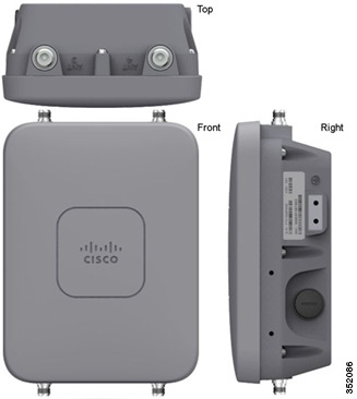
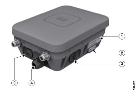
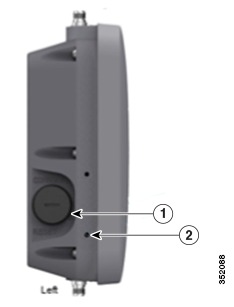
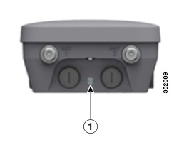
The 1532 is an ultra low-profile outdoor access point, designed to blend seamlessly into its environment. The 1532 has 2 Gigabit Ethernet ports, the PoE-in port, which is the main WAN port, and an additional LAN port. The PoE-in port should be used to power the access point and connect to a WLC. The LAN port will be used for Ethernet Bridging and Daisy chaining. The 1532 can be powered either by PoE-in, using a PoE injector, or by 48 VDC. The PoE injector can power the access point even if the access point has no WAN connectivity and is operating as a Mesh AP. The Console port is located on the side of the Access Point, covered by a plastic cap. There is a reset button located under the cap as well. The Solar Shield Screw holes are used to secure the Solar Shield add-on, if the access point needs to be painted to match its environment. The LED can be used to determine the status of the access point. The LED flashing sequences are listed as part of this document.The AP 1532E has four antenna ports with N-Type connectors, two at the top of the access point and two at the bottom of the access point. When in Dual band mode, the bottom antenna ports (port 1 and port 2) are used for both 2.4 GHz and 5 GHz. Antennas that support multiple bands are called Dual Radiating Element (DRE), they contain dual radiating elements for both the 2.4 GHz and 5 GHz band inside the antenna.
Note
The Flexible Antenna Port Connectors are only present on the 1532E.When in Single band mode, the bottom antenna ports (port 1 and port 2) are used for 2.4 GHz antennas, and the top ports are for 5 GHz (port 3 and port 4). Antennas that support a single band are Single Radiating Elements (SRE), they contain single radiating elements inside the antenna. The AP 1532I has internal antennas and its internal antennas cannot be configured as part of the Flexible antenna port feature.Antenna Options for the AP 1532E
The AP 1532 has the same antenna options as the 1552 series with only one new addition, the AIR-ANT2547VG-N, which has the same performance as the AIR-ANT2547V-N, but gray in color.
Product ID Freq. Band Gain Type Required Quantity AIR-ANT2547V-N 2.4 / 5 GHz 4 / 7 dBi Omnidirectional 2 AIR-ANT2547VG-N 2.4 / 5 GHz 4 / 7 dBi Omnidirectional 2 AIR-ANT2588P3M-N= 2.4 / 5 GHz 8 / 8 dBi Directional 120x30° 1 AIR-ANT2450V-N= 2.4 GHz 5 dBi Omnidirectional 2 AIR-ANT2480V-N= 2.4 GHz 8 dBi Omnidirectional 2 AIR-ANT2413P2M-N= 2.4 GHz 13 dBi Directional 30x30° 1 AIR-ANT5180V-N= 5 GHz 8 dBi Omnidirectional 2 AIR-ANT5114P2M-N= 5 GHz 14 dBi Directional 30x30° 1 AP 1532 Power Supplies
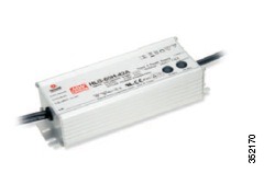
The AP 1532 can be powered either by direct 24-48 VDC, using the AC/DC power adapter with the AIR-PWRADPT-1530=, or by Power over Ethernet. The AP 1532I requires Universal PoE (UPoE), which supplies 60 W of power. The AP 1532E operates with PoE+ or 802.3at, which supplies 25.5 W of power. Here is a list of powering options for the AP1532 series.
Model Configuration Regulatory Domain Switch Power AIR-PWRINJ1500-2= AIR-PWRINJ4= AC/DC Power Adapter AIR-PWRADPT-1530= 1532I 3x3:3 (2.4 GHz) 2x3:2 (5 GHz)
A, D, K, N, Q, T, Z UPoE √ √ one Tx disabled* 2x3:2 (2.4 GHz)
2x3:2 (5 GHz)
A, D, K, N, Q, T, Z 802.3at PoE+ N/A √ N/A 3x3:3 (2.4 GHz) 2x3:2 (5 GHz)
C, E, F, H, M, R, S 802.3at PoE+ √ √ √ 1532E 2x2:2 (2.4 GHz) 2x2:2 (5 GHz)
all 802.3at PoE+ √ √ √ AP 1532 Accessories
The following accessories are available with the AP 1532:
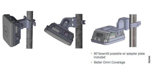
- AIR-ACC1530-PMK1 (=) - Wall/Pole mount bracket, available as an orderable option or as an add-on.
- AIR-ACC1530-PMK2= - Wall/Pole mount bracket with tilt mechanism, orderable as an add-on.
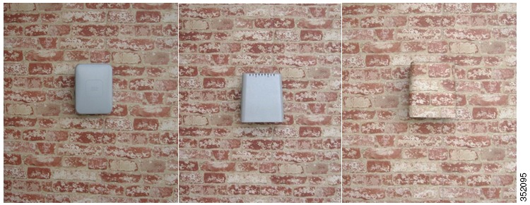
- AP1532 Solar Shield Cover (AIR-ACC1530-CVR=) - Cover / Solar Shield for 1532, orderable as an add-on. This accessory is paintable. Below is an example of the AP 1532, followed by the AP 1532 with AIR-ACC1530-CVR=, then a painted AIR-ACC1530-CVR=
- AIR-PWRADPT-1530= - AC/DC power adapter, orderable as an add-on.
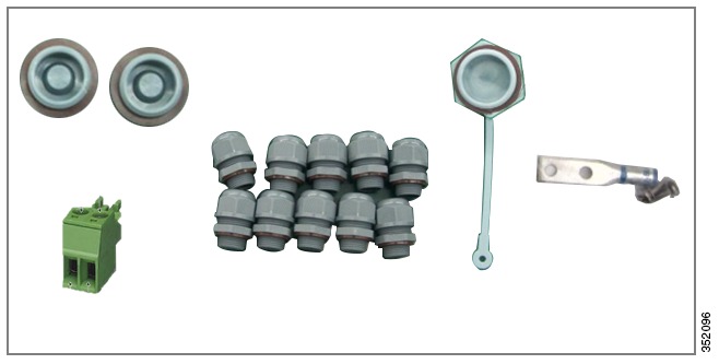
- AIR-ACC1530-KIT1= - Extra cable glands, power connector, ground lug, and Ethernet caps.
Note
For more details please visit the 1532 Hardware Installation guide: http://www.cisco.com/en/US/docs/wireless/access_point/1530/installation/guide/1530hig.html
Flexible Antenna-Port Configuration
There are two terms that are used when referring to Antenna Band Mode Configurations:
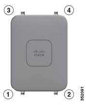
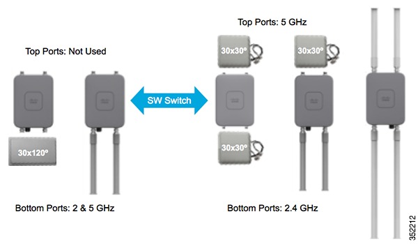
- Dual Antenna Band Mode – The bottom two ports, port 1 and port 2, are used for dual band 2.4 GHz/5 GHz Dual Radiating Element (DRE) antennas.
- Single Antenna Band Mode – The top two ports, port 3 and port 4, are used for 5 GHz Single Radiating Element (SRE) antennas while the bottom two ports, port 1 and port 2, are used for 2.4 GHz SRE antennas.
Please note that Antenna Band Mode is only available on the 1532E model, with external antennas; the 1532I has an internal antenna and does not require additional antennas.
Configuring Antenna Band Mode from the WLC GUI
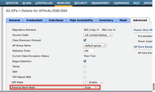
To change the Antenna Band Mode in the WLC GUI, navigate to the Wireless > Access Point > AP_NAME > Advanced page. Then select Dual or Single from the Antenna Band Mode list:
Note
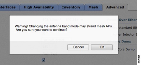
Misconfiguring the Antenna Band Mode can strand a mesh AP, please make sure your physical antennas are properly configured before changing the Antenna Band Mode. A warning message will be displayed to confirm the changes.Configuring Antenna Band Mode from the WLC CLI
The Antenna Band Mode can be changed via the WLC CLI by issuing the command:(Cisco Controller) >config ap antenna-band-mode <single|dual> <ap_name>The Antenna Band mode can be displayed by issuing the command:(Cisco Controller) >show ap config general <AP_NAME>The output will contain many fields, one of which is the Antenna Band Mode:Antenna Band Mode ............................... DualDaisy Chaining with AP 1532
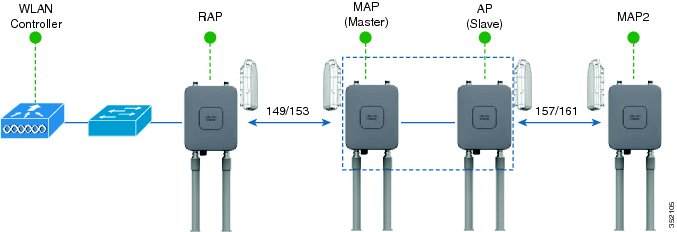
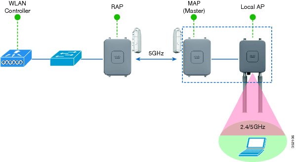
One of the key features of the 1532 access point is the ability to “daisy chain” access points while they are operating as Mesh APs (MAPs). By “daisy chaining” MAPs, customers can either operate the access points as a serial backhaul, allowing different channels for uplink and downlink access thus improving backhaul bandwidth, or to extend universal access across a mesh network. Extending universal access allows a customer to connect a local mode or flexconnect mode 1532 access point to the Ethernet port of a MAP, thus extending the network to provide better client access. These features will be explained in greater detail in the following sections.
There are two roles of a daisy-chained access point, the Master AP and Slave AP. The Master AP must be configured as a Mesh AP (MAP), it is also recommended to set a preferred-parent and Bridge-group name. The Slave AP can either be configured as a Bridge Mode Root AP if used for serial backhaul or as a Local/Flexconnect Mode AP if used for extended universal access.
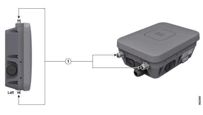
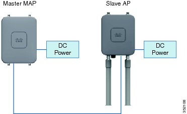
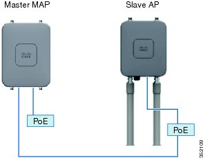
Daisy-chained access points need to be cabled differently depending on how the APs are powered. If the access point is powered via DC power, an Ethernet cable should be connected directly from the LAN port of the Master AP to the PoE-in port of the Slave AP.If the access point is powered via PoE, an Ethernet cable must be connected from the LAN port of the Master AP into the PoE Injector, which powers the Slave AP.Requirements for Daisy Chaining AP 1532s
When configuring a daisy chaining deployment, there are a few key components to address:
- The uplink daisy-chained AP is considered the Master AP, the connected AP is considered the Slave AP.
- The Master AP must be configured as Mesh AP (MAP).
- The Slave AP must be configured either as Bridge Mode Root AP or a local/Flexconnect AP, but not as a Mesh AP. If the Slave AP is configured as a MAP there is risk of a layer 2 bridging loop.
- The connecting Ethernet cable must go from the LAN port of the Master AP to the PoE-in port of the Slave AP.
- There should be a preferred parent set for each daisy-chained mesh hop. The Master MAP will have a preferred parent assigned.
- Daisy-chaining must be enabled on the Slave APs when they are configured as RAPs, either via WLC GUI, WLC CLI, or AP CLI.
- Directional Antennas should be used when creating a daisy chain; these should be used to guide the mesh tree formation to the customer’s needs.
- There can only be one slave AP per Master AP. One Master AP to multiple Slave APs is not supported.
- The Slave AP should be connected directly to the LAN Ethernet port of the Master AP. There should be no other layer 2 switching devices in-between.
- APs 1532I and 1532E can be used interchangeably as the master and the slave AP.
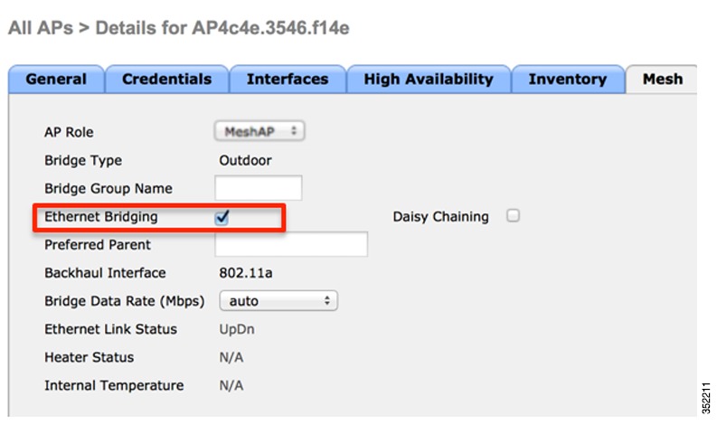
- Ethernet Bridging must be enabled on the Master AP.
- Enabling Daisy Chaining using the WLC GUI
- Enabling Daisy Chaining using the WLC CLI
- Enabling Daisy Chaining Using the AP CLI
Enabling Daisy Chaining using the WLC GUI
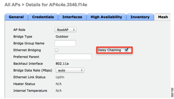
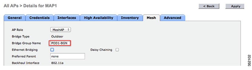
Ethernet Bridging must be enabled on the Master AP, which is configured as a MAP. To enable Ethernet Bridging, navigate to Wireless > Access Point > MASTER AP NAME > Mesh tab, and then check the Ethernet Bridging checkbox.Daisy chaining should only be enabled on a Slave AP that is configured as a Bridge Mode Root Access Point, for all other daisy-chaining configurations, daisy chaining does not need to be enabled. To enable Daisy Chaining from the WLC GUI, navigate to the Wireless > Access Point >AP NAME > Mesh tab, and then check the Daisy Chaining check box.Enabling Daisy Chaining using the WLC CLI
Ethernet Bridging must be enabled on the Master AP, which is configured as a MAP.
To enable Ethernet Bridging on the Master MAP, issue the command:(Cisco Controller) >config ap bridging [enable/disable] <ap_name>Daisy chaining should only be enabled on a Slave AP that is configured as a Bridge Mode Root Access Point, for all other daisy chaining configurations, daisy chaining does not need to be enabled.
To enable Daisy Chaining from the WLC CLI, issue the command:(Cisco Controller) >config ap daisy-chaining [enable/disable] <ap_name>The daisy chaining feature must be enabled on a per access point basis.(Cisco Controller) >show ap config general <ap_name>Then scroll down to the Daisy Chaining entry:Daisy Chaining .................................. DisabledEnabling Daisy Chaining Using the AP CLI
Daisy-chaining should only be enabled on a Slave AP that is configured as a Bridge Mode Root Access Point, for all other daisy chaining configurations, daisy chaining does not need to be enabled.
To enable Daisy Chaining from the AP CLI, issue the command:AP#capwap ap daisy-chaining <enable/disable>The Master MAP must have Ethernet Bridging Enabled.
Preferred Parent
Preferred parent is a mechanism to configure a child with a pre-determined parent as part of the Cisco Adaptive Wireless Path Protocol (AWPP), which is Cisco's Layer 2 wireless protocol. The child AP selects the preferred parent based on the following conditions:
- Preferred parent is the best parent.
- Preferred parent has a link SNR of at least 20 db.
- Preferred parent has a link SNR in the range 12 dB to 20 dB, but no other parent is significantly better (SNR more than 20% is better). For SNR lower than 12 dB, the configuration is ignored.
- Preferred parent is not blacklisted.
- Preferred parent is not in silent mode because of dynamic frequency selection (DFS).
- Preferred parent is in the same bridge group name (BGN). If the configured preferred parent is not in the same BGN, and no other parent is available, the child will join the parent AP using the default BGN.
Note
Only Bridge Mode MAPs should be set with a preferred parent.Set a Preferred Parent via the WLC GUI
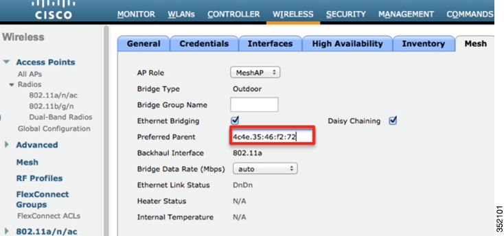
A Preferred Parent can be set via the WLC GUI by navigating to the Wireless > Access Points > AP_NAME > Mesh tab, and then entering the MAC address of the Preferred Parent. Click Apply.
Note
When the preferred parent is entered, no other mesh configurations can be submitted at the same time. You must apply the changes, wait 90 seconds, then other mesh changes can be made.
Note
To clear the Preferred Parent text box, the value "none" must be entered then submitted.Set a Preferred Parent via the WLC CLI
Preferred Parents can also be set via the WLC CLI, by issuing the command:(Cisco Controller) >config mesh parent preferred <ap_name> <PARENT_MAC_ADDRESS>An access point's preferred parent can be seen by issuing:(Cisco Controller) >show ap config general <ap_name>Then scroll down the Mesh preferred parent entry:Mesh preferred parent ........................... 00:24:13:0f:92:00Bridge Group Name
Bridge group names (BGNs) are used to logically group mesh APs to avoid two networks on the same channel from communicating with each other. This is a way to form independent mesh trees within a single mesh network. Despite having a BGN set, an AP can still join a mesh network with a non-matching BGN if there are no parents of its matching BGN available. This is to prevent the AP from being stranded. If the AP joins another BGN, after 15 minutes, the AP will drop AWPP and scan for its own BGN. This process will repeat until the AP joins a mesh network with a matching BGN.
Note
BGN misconfigurations will cause network instability.Deployment Modes
Bridge Mode Deployment
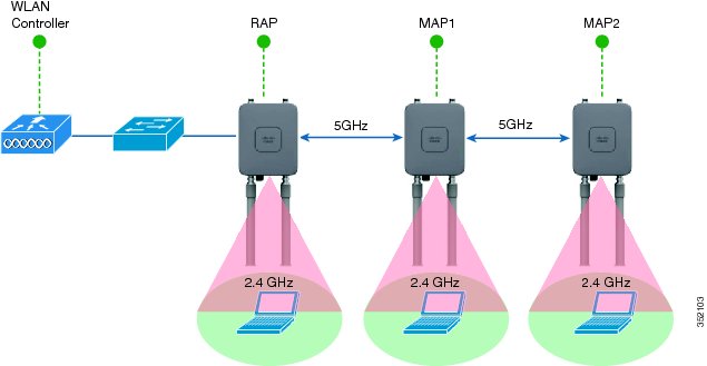
This is your typical mesh configuration. RAPs have wired connections to their controller, the MAPs have wireless connections to their controller. MAPs communicate among themselves and back to the RAP using wireless connections over the 802.11a/n radio backhaul. MAPs use the Cisco Adaptive Wireless Path Protocol (AWPP) to determine the best path through the other mesh access points to the controller.Daisy Chaining as a Serial Backhaul
The 1532 Daisy chaining feature can be used to provide a serial backhaul mesh. The Master MAP has a preferred parent selected as the RAP. The Slave MAP has no preferred parent selected. High gain directional antenna should be used in typical serial backhaul deployments. In addition, "Preferred Parent" configurations should be used to create serial backhaul mesh networks.
- Only 1532s in Bridge Mode can utilize this configuration.
- Master MAP & Slave MAP are operating on different 5 GHz channels to maximize throughput across the mesh link.
- BGN configuration and the Preferred Parent command are recommended to maintain the mesh tree.
- Slave MAP must be configured in RAP Mode.
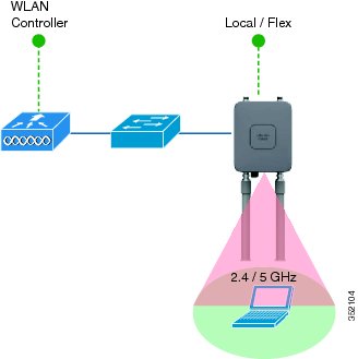
Extended Universal Access Using Daisy Chaining
The 1532 Daisy chaining feature can be used to extend Universal Access across a Mesh network. In this example, the Master MAP is backhauled wirelessly with the RAP. The Slave MAP is operating in local/Flex-connect mode and is providing client access on both the 2.4 GHz and 5 GHz radio.Autonomous Software
Unified to Autonomous Conversion
By default the AP 1532 is set to unified mode. Before the 1532 access point joins a WLC, it can be changed to aIOS mode by issuing:AP#capwap ap autonomous Convert to Autonomous image. Proceed? (yes/[no]):
Note
This command should only be issued once, during initial priming of the Access Point.If the AP has already joined a WLC, you need to convert the image using the following command from the AP console:AP#archive download-sw /force-reload /overwrite tftp://<tftp ip address>/<image name.tar> AP#archieve download-sw /force-reload /overwrite tftp://10.0.0.5/ap1g3-k9w7-tarNote that the k9w7 denotes the autonomous image. The autonomous image can be found at cisco.com.
Autonomous to Unified Conversion
To switch back from autonomous to Unified please follow these instructions:AP#archive download-sw /force-reload /overwrite tftp://<tftp ip address>/<image name.tar> AP#archieve download-sw /force-reload /overwrite tftp://10.0.0.5/ap1g3-k9w8-tarNote that the k9w8 denotes the unified image. The unified image can be found at cisco.com.
Autonomous LED Flashing Sequence for Link Alignment
Signal Level (dBm) LED (Status) >-44 Constant green –47 to –44 Blinking green fast –50 to –47 Blinking green medium –53 to –50 Constant amber –57 to –53 Blinking amber fast –60 to –57 Blinking amber medium –63 to –60 Blinking amber slow –66 to –63 Blinking red slow –69 to –66 Blinking red medium –72 to –69 Blinking red fast –75 to –72 Constant red < –75 Off Design and Planning with the 1532 Access Point
Deploying an outdoor mesh network requires careful planning and design. RF Nature: Not an Exact Science, Especially in Unlicensed Spectrum. There can be many other devices that can interfere with our mesh network. To optimize the deployment we can follow these recommendations:
- Mesh: AP-to-AP Backhaul Distance Capability should be - 2x AP-to-Client.
- WiFi Network Planning Involves:
- Site Survey to Identify: AP Location & Height, Line-of-Sight (LoS)/Partial LoS, Interference, Access to wired backhaul (i.e. Max # Hops).
- Knowledge of the client type (Smart Phones, Tablets, Laptops).
- User Experience: Minimum Throughput to User, Type of Applications (Internet, Video, Gaming).
- CAPEX & OPEX available for project: Match to type of Service, and Robustness of Coverage.
- Regulatory Considerations: different countries allow different Tx power at different Frequency Bands.
- When to use internal antenna 1532 versus the external antenna 1532.
Based on these considerations, below are estimations for both the – A and – E domains:Assumptions:
- Height: APs are at 33 Ft (10 m), and Client at 3.3 ft (1 m)
- Throughput: > 1 Mbps
- Decreasing AP-AP distance improves consumer experience (throughput, latency).
- Near LoS suburban. For Less LoS Scenarios; Reduce Distance Assumptions.
- Flat Terrain Environment.
- Comparing the 1532I to the 1532E with AIR-ANT2547V-N dual band antennas. The 1532E with high-gain antennas can reach much greater AP to AP distances.
Troubleshooting
The following AP 1532 LED behavior will notify users of the status of the Access Point:
Type LED State AP Action Boot loader status sequence Blinking GREEN DRAM memory test in progress DRAM memory test OK Board initialization in progress Initializing FLASH file system FLASH memory test OK Initializing Ethernet Ethernet OK Starting Cisco IOS Initialization successful Association status Chirping GREEN Normal operating condition, joined to a controller, but no wireless client associated. GREEN Normal operating condition, at least one wireless client association. Operating status Blinking AMBER Software upgrade in progress. Cycling through GREEN, RED, and AMBER Discovery/join process in progress. Rapidly cycling through RED, GREEN, AMBER, and OFF Access Point location command invoked Blinking RED Ethernet link not operational Boot loader warnings Blinking AMBER Configuration recovery in progress (MODE button pushed for 2 to 3 seconds) RED Ethernet failure or image recovery (MODE button pushed for 20 to 30 seconds) Blinking GREEN Image recovery in progress (MODE button released) Boot loader errors RED DRAM memory test failure. Blinking RED and AMBER FLASH file system failure. Blinking RED and off Environment variable failure. Bad MAC address. Ethernet failure during image recovery. Boot environment failure. No Cisco image file. Boot failure. Cisco IOS errors RED Software failure; try disconnecting and reconnecting unit power. Cycling through RED, GREEN, AMBER, and OFF General warning; insufficient inline power.