Feedback Feedback
|
Table Of Contents
Enabling WEB GUI on both the 5760 and 3850 Platforms
GUI access for CT5760/3850 Example
Basic Configuration for the CT5760/3850 Example
AAA Configuration for 802.1x WLAN Example
801.1x WLAN Configuration Example
Creating a Switch Peer Group (SPG) on Mobility Controller 5760 Example
Configuring Mobility between Mobility Agent (3850) and Mobility Controller (5760) Example
Exercise - Verify New Mobility on MA 3850 and MC 5760
Monitoring: Verify AP Registration Example
Monitoring: Verify Client Connectivity Example
Configure Mobility Oracle, Mobility Peer and Verify Statistics on MC 5760 Example
Managing CT5760/Cat3850 with Cisco Prime Infrastructure 2.0 Example
Cisco Unified Access CT5760 Controllers, Catalyst 3850 Switches IOS XE Software Release 3.2.2 Web GUI Deployment Guide
Last Updated: August, 2013
Introduction
This document introduces the Maintenance Release 3.2.2 Web GUI functionality for the Cisco Converged Access CT5760 and Cat3850 products. This guide is designed to help you access, configure and monitor both products using the GUI Web interface.
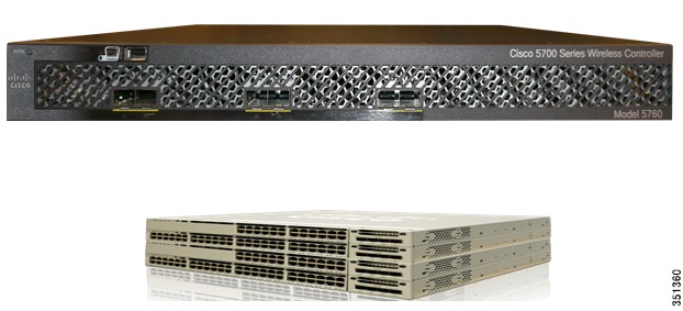
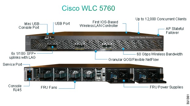
CT5760 Controller
CT5760 is an innovative UADP ASIC based wireless controller deployed as a centralized controller in the next generation unified wireless architecture. CT5760 controllers are specifically designed to function as the Unified model central wireless controllers. They also support the newer Mobility functionality with Converged Access switches in the wireless architecture.
CT5760 controllers will be deployed behind a core switch/router. The core switch/router will be the only gateway into the network for the controller. The uplink ports connected to the core switch will be configured as EtherChannel trunk to ensure port redundancy.
This new controller is an extensible and high performing wireless controller, which can scale up to 1000 access points and 12000 clients. The controller has 6-10 Gbps data ports.
As a component of the Cisco Unified Wireless Network, the 5760 series works in conjunction with Cisco Aironet access points, the Cisco Prime infrastructure and the Cisco Mobility Services Engine to support business-critical wireless data, voice, and video applications.
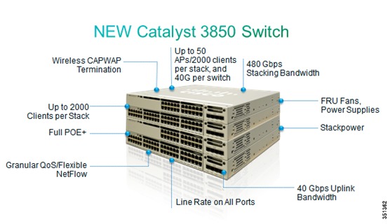
Catalyst 3850 Controller
Unified Access Catalyst 3850 switches are innovative UADP ASIC hardware that can support multiple protocols and has many advantages over the current hardware platform. CAT3850 switch has an integrated hardware based wireless support with CAPWAP and fragmentation. The CAT3850 switch has 40gig of uplink bandwidth with all port functioning at line rate.
The CAT3850 switches provide Open Service platform. It is a 4 core CPU to leverage the OS and to host various services. The CAT3850 hardware is the Next-Gen switching hardware.
UA CAT3850 switches have unified wired and wireless architecture. The wireless operating system is IOS based. UA CAT3850 switches provide uniform wired and wireless policies. The CAT3850 switch can manage 50 access points-802.11n and support 2000 clients per stack.
Getting Started
Before you get started with enabling the WEB GUI on the Cat3850/CT5760, make sure you have the following:
1.
CLI access to the box. Console Access information is shown in the CLI/Console Access section below.
2.
3.
4.
Supported Browser Version
Below is a list of supported browser versions:
•
•
•
CLI/Console Access
Before you configure the switch or controller for basic operations, you must connect it to a PC that uses a VT-100 terminal emulator (such as HyperTerminal, ProComm, or Putty).
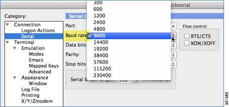
The controller has both EIA/TIA-232 asynchronous (RJ-45) and USB 5-pin mini Type B, 2.0 compliant serial console ports. The default parameters for the console ports are 9600 baud, eight data bits, one stop bit, and no parity. The console ports do not support hardware flow control. Choose the serial baud rate of 9600; if you have issues, try a baud rate of 115200. The figure below shows an example of a Mac Secure CRT; use similar configuration for PC/Windows Putty, and so on.
Figure 1 Mac Secure CRT Example
Enabling WEB GUI on both the 5760 and 3850 Platforms
Both the Cat3850 and CT5760 currently ship with the first release labeled as 3.2.01. If you have an existing CAT3850/CT5760 and want to use GUI to configure/monitor your wireless network, please follow the steps below:
1.
Note
2.
3.
Controller(config)#username admin privilege 15 password Cisco123.Or you can configure it to use credentials using an authentication server. Make sure the user has privilege 15 access level.4.
5.
Note
Configuration Examples
If you require additional information regarding any of the field while going through the deployment guide, please refer to the GUI online Help available after you have successfully accessed the GUI through the steps below.
GUI access for CT5760/3850 Example
Complete these steps:
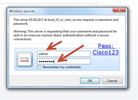
Step 1
https://10.10.10.5
username: admin
Password: Cisco123
Note
Controller(config)#username admin privilege 15 password Cisco123. This is an example and not the default username and password.
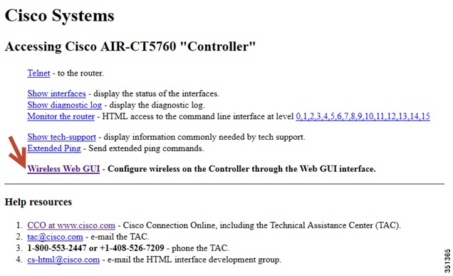
Once you login, you will be directed to the following page:
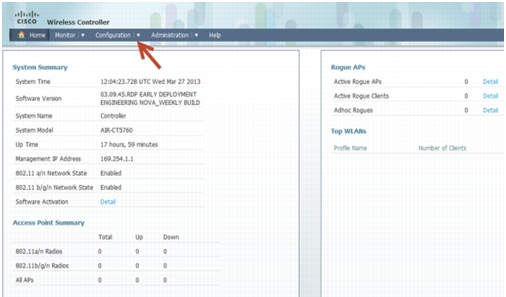
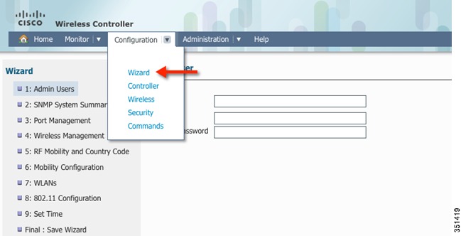
Step 2
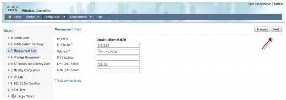
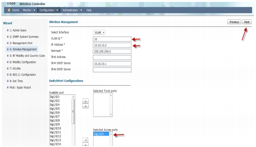
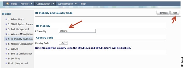
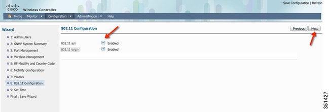
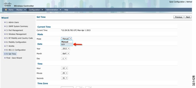
Basic Configuration for the CT5760/3850 Example
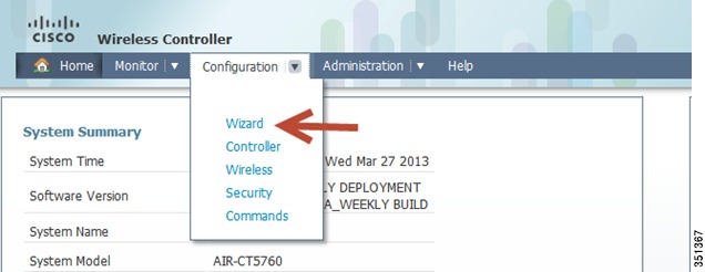
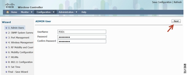
In this section you will perform basic controller and management configuration using the GUI Wizard of the CT5760 or CAT 3850.
Step 3
Step 4
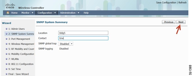
Step 5
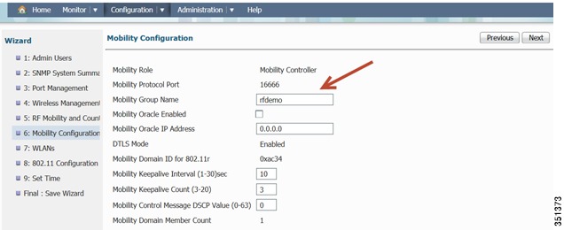
Step 6
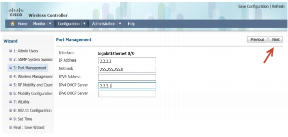
Step 7
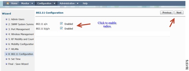
Step 8
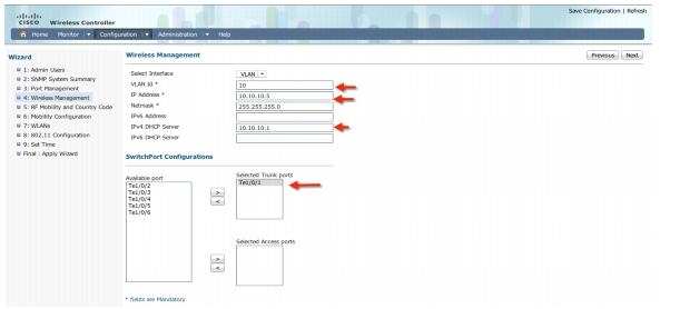
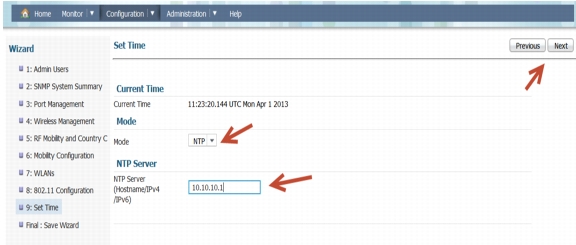
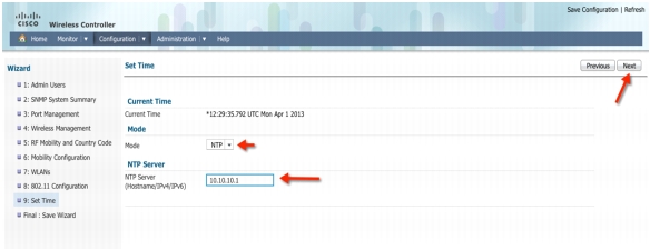
Step 9
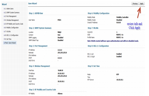
Step 10
Step 11
Step 12
Step 13
Step 14
Note
AAA Configuration for 802.1x WLAN Example
In this section you will setup AAA configuration.
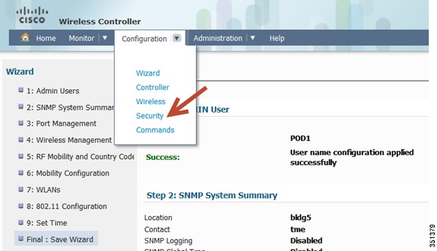
Step 15
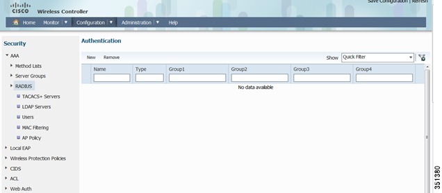
This will take you to the AAA configuration page:
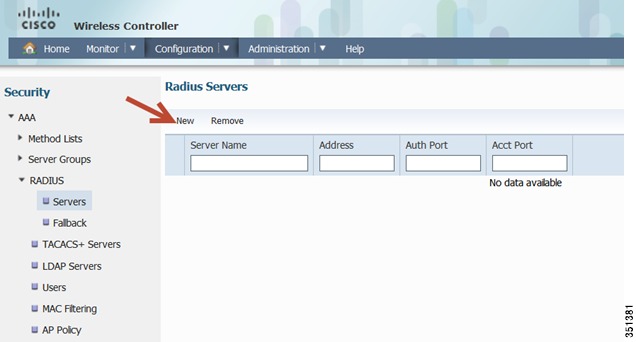
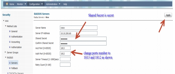
Step 16
Please enter the ISE/Radius server information as shown below. Once done, Click Apply.
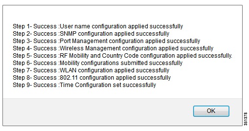
Confirmation message:
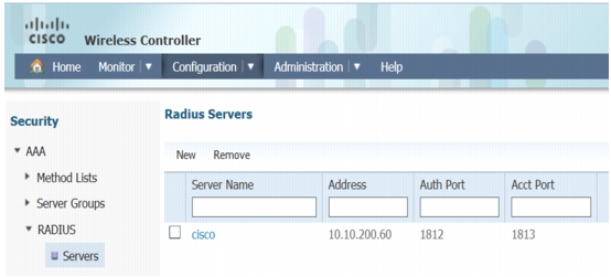
Click Ok and you should see the following window.
Step 17
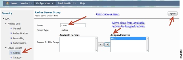
Once you click Apply, a confirmation pop-up appears:
Click Ok and confirm the server group cisco is created.
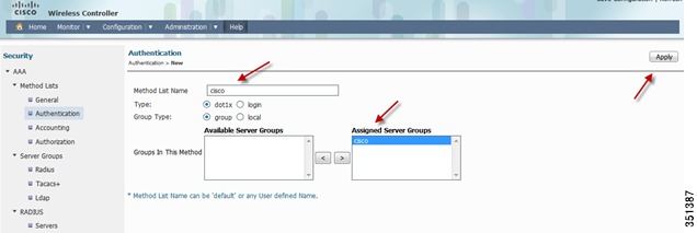
Step 18
Once you click Apply, a confirmation pop-up appears:
Click Ok and confirm the server group cisco is created.
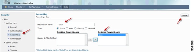
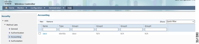
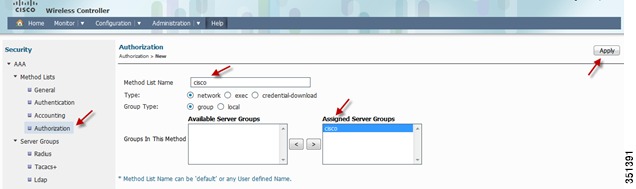
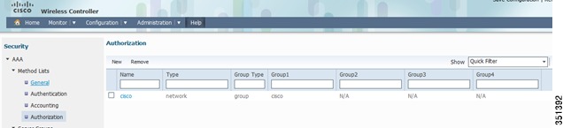
Repeat the same Step for Accounting and Authorization:
Accounting
Authorization
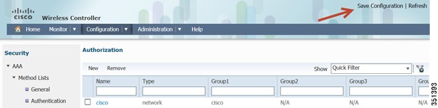
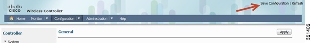
This will conclude Radius and AAA configuration. Next section is WLAN settings. Before moving on, please Save your configuration by clicking on Save Configuration in the upper right hand side of the GUI.
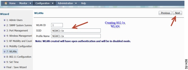
801.1x WLAN Configuration Example
In this section you will perform 802.1x WLAN configuration using ISE as a radius server
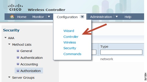
Step 19
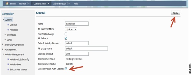
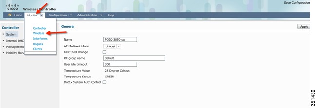
Under Configuration tab, navigate to Controller > System > General
Enable Dot1x System Auth Control and click Apply. Once you get a confirmation message, move to the next step.
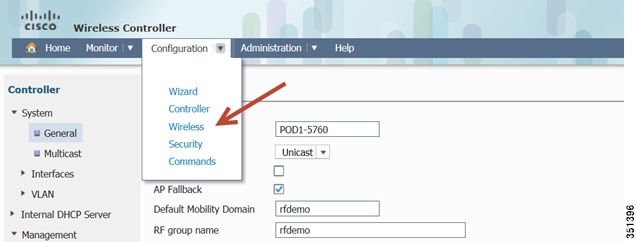
Step 20
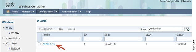
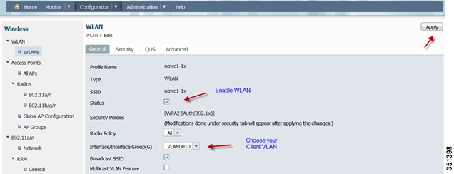
Navigate to Wireless > WLAN, you should see the WLAN summary page:
Select WLAN NGWC1-1x and then you will be able to edit its settings.
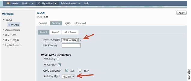
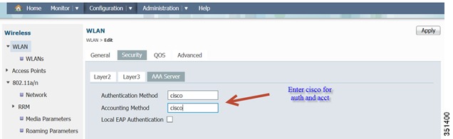
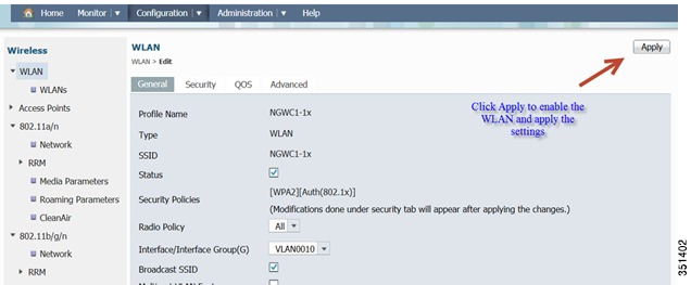
Step 21
Under WLAN > Security > AAA Server, type cisco as the Authentication and Accounting Methods that we have created earlier under AAA.
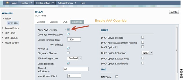
Under WLAN > Advanced, Enable Allow AAA Override
Now Click Apply to enable the WLAN and its settings.
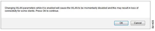
Once you click Apply, you will be prompted with the message below. Click Ok.
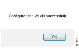
Confirmation message appears. Click Ok.
Step 22
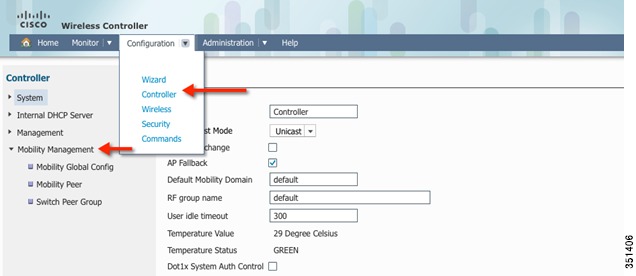
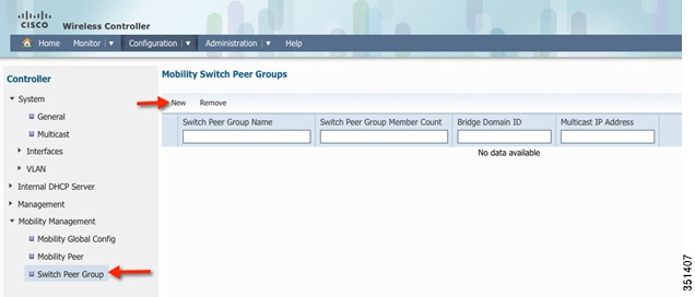
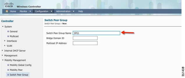
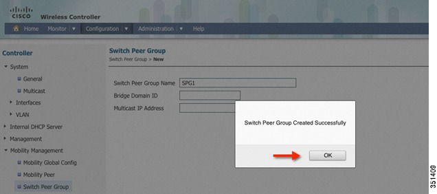
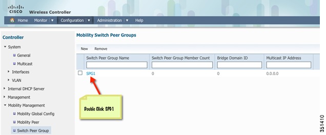
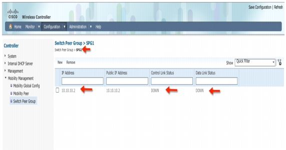
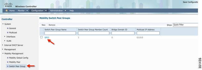
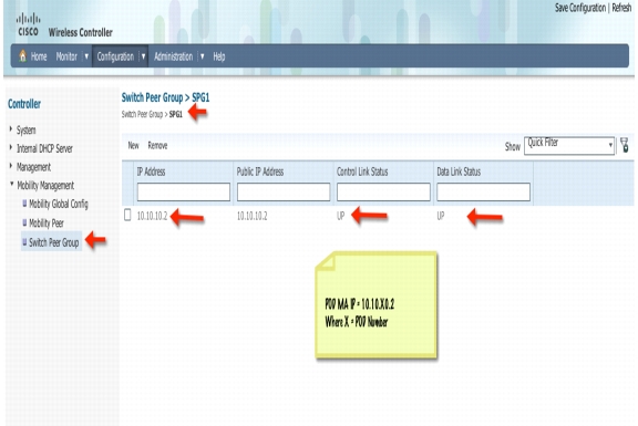
Creating a Switch Peer Group (SPG) on Mobility Controller 5760 Example
In this section, you will be able to configure Switch Peer Group(SPG) and add members (Mobility Agent) to the Group on the Mobility Controller (MC).
Step 23
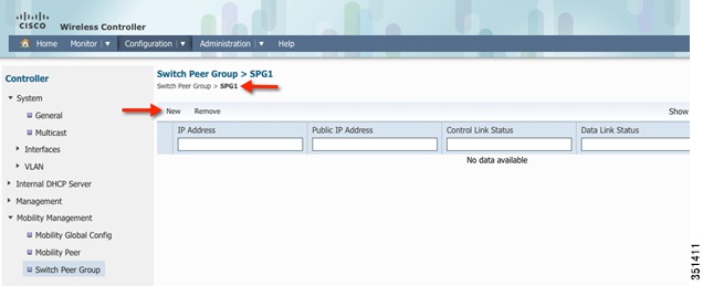
Step 24
Step 25
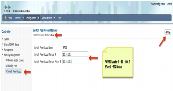
Step 26
Step 27
Step 28
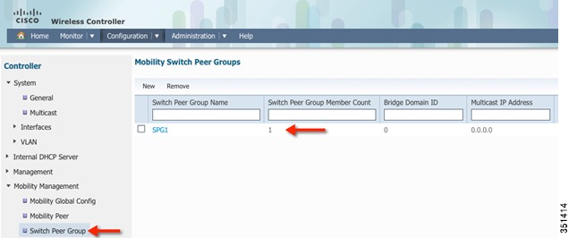
Step 29
Step 30
You can repeat this step to additional MA to the switch group or create a different SPG name.
Step 31
Step 32
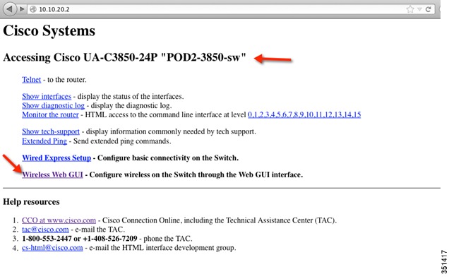
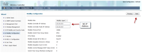
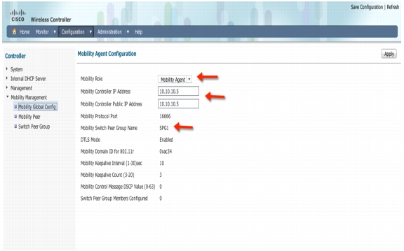
Configuring Mobility between Mobility Agent (3850) and Mobility Controller (5760) Example
Step 33
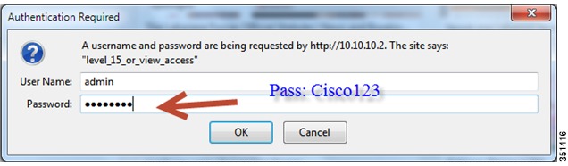
Open a browser and type your 3850 IP address. For example:
https://10.10.10.2
Enter username: admin
Password: Cisco123
Step 34
Step 35
Step 36
Step 37
Step 38
Step 39
Step 40
Note
Step 41
Step 42
Step 43
Step 44
Step 45
Step 46
Step 47
Step 48
Note
Step 49
Exercise - Verify New Mobility on MA 3850 and MC 5760
Step 50
Step 51
Step 52
https://10.10.10.5
Step 53
Step 54
Step 55
Step 56
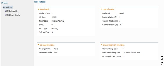
Monitoring: Verify AP Registration Example
In this section, you monitor and verify AP and Client connectivity.
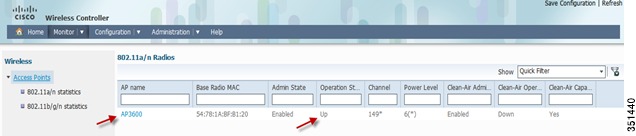
Step 57
Step 58
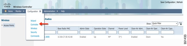
Click the AP and you can check the radio stats, Channel assignment and RF Parameters
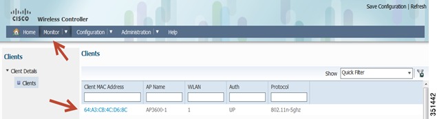
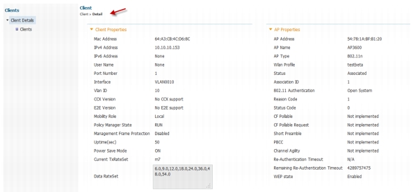
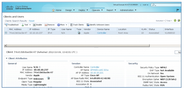
Monitoring: Verify Client Connectivity Example
Step 59
Client Details
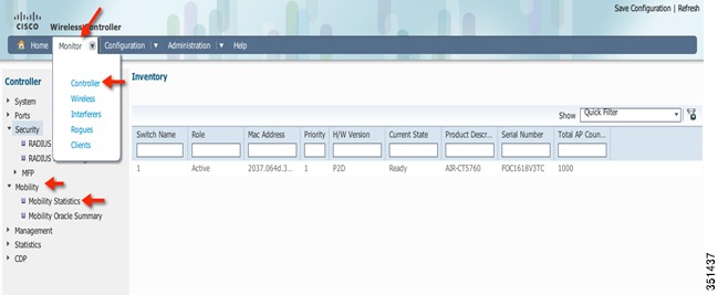
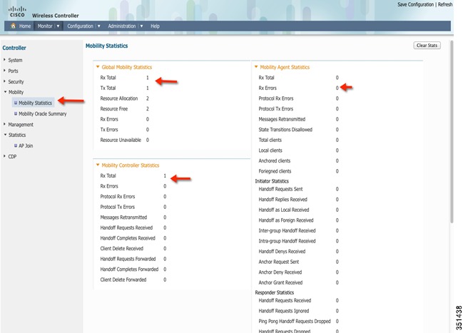
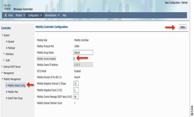
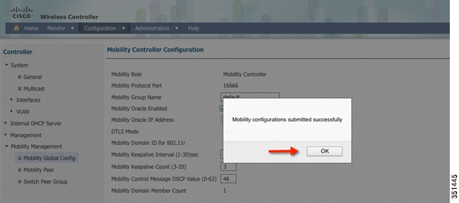
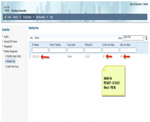
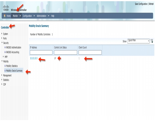
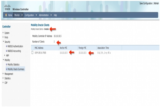
Configure Mobility Oracle, Mobility Peer and Verify Statistics on MC 5760 Example
Step 60
Step 61
Step 62
Step 63
Step 64
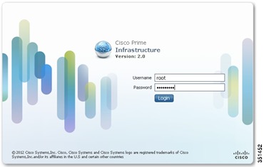
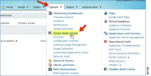
Managing CT5760/Cat3850 with Cisco Prime Infrastructure 2.0 Example
In this section you will:
•
•
•
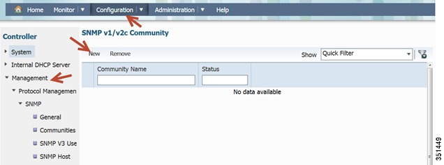
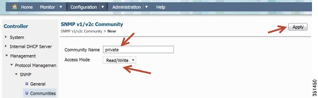
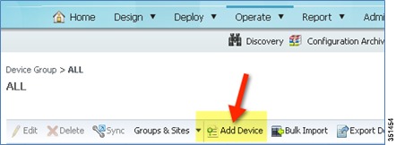
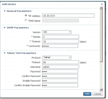
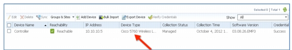
Step 65
Configure SNMP strings for private and public
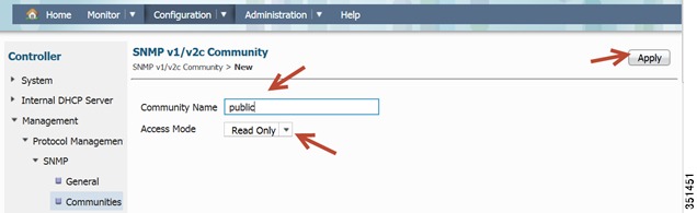
Repeat the same step for a public Community
Step 66
Step 67
Step 68
Step 69
a.
b.
c.
•
•
•
•
Step 70
Step 71
Step 72