-
Cisco IOS Software Configuration Guide for Cisco Aironet Access Points, 12.3(4)JA
-
Preface
-
Overview
-
Configuring the Access Point for the First Time
-
Using the Web-Browser Interface
-
Using the Command-Line Interface
-
Administering the Access Point
-
Configuring Radio Settings
-
Configuring Multiple SSIDs
-
Configuring an Access Point as a Local Authenticator
-
Configuring Cipher Suites and WEP
-
Configuring Authentication Types
-
Configuring WDS, Fast Secure Roaming, Radio Management, and Wireless Intrusion Detection Services
-
Configuring RADIUS and TACACS+ Servers
-
Configuring VLANs
-
Configuring QoS
-
Configuring Filters
-
Configuring CDP
-
Configuring SNMP
-
Configuring Repeater and Standby Access Points and Workgroup Bridge Mode
-
Managing Firmware and Configurations
-
Configuring System Message Logging
-
Troubleshooting
-
Channels and Antenna Settings
-
Protocol Filters
-
Supported MIBs
-
Error and Event Messages
-
Glossary
-
Index
-
 Feedback
Table Of Contents
Checking the Top Panel Indicators
Indicators on 1130AG Access Points
Resetting to the Default Configuration
Using the Web Browser Interface
Reloading the Access Point Image
Using the Web Browser Interface
Obtaining the Access Point Image File
Obtaining TFTP Server Software
Troubleshooting
This chapter provides troubleshooting procedures for basic problems with the wireless device. For the most up-to-date, detailed troubleshooting information, refer to the Cisco TAC website at the following URL (select Top Issues and then select Wireless Technologies):
Sections in this chapter include:
•
Checking the Top Panel Indicators
•
•
Checking the Top Panel Indicators
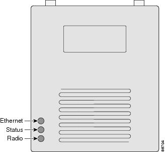
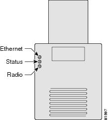
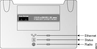
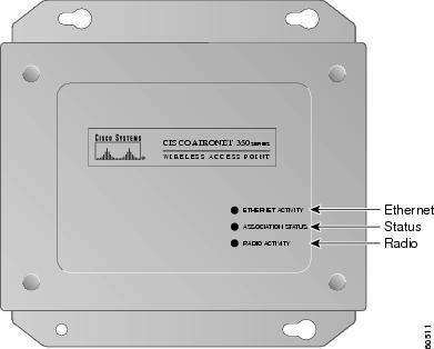
If your wireless device is not communicating, check the three LED indicators on the top panel to quickly assess the device's status. Figure 21-1 shows the indicators on the 1200 series access point. Figure 21-2 shows the indicators on the 1100 series access point. Figure 21-3 and Figure 21-4 show the indicators on the 350 series access point.
Note
Figure 21-1 Indicators on the 1200 Series Access Point
Figure 21-2 Indicators on the 1100 Series Access Point
Figure 21-3 Indicators on the 350 Series Access Point (Plastic Case)
Figure 21-4 Indicators on the 350 Series Access Point (Metal Case)
The indicator signals on the wireless device have the following meanings (for additional details refer to Table 21-1):
•
•
•
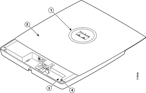
Indicators on 1130AG Access Points
If your access point is not working properly, check the LED ring on the top panel or the Ethernet and Radio LEDs in the cable bay area. You can use the LED indications to quickly assess the unit's status. Figure 21-1 shows the access point LEDs.
Figure 21-5 1130AG Access Point LEDs
Note
The LED signals are listed in Table 21-2.
Checking Basic Settings
Mismatched basic settings are the most common causes of lost connectivity with wireless clients. If the wireless device does not communicate with client devices, check the areas described in this section.
SSID
Wireless clients attempting to associate with the wireless device must use the same SSID as the wireless device. If a client device's SSID does not match the SSID of an wireless device in radio range, the client device will not associate. The wireless device default SSID is tsunami.
WEP Keys
The WEP key you use to transmit data must be set up exactly the same on the wireless device and any wireless devices with which it associates. For example, if you set WEP Key 3 on your client adapter to 0987654321 and select it as the transmit key, you must set WEP Key 3 on the wireless device to exactly the same value. The wireless device does not need to use Key 3 as its transmit key, however.
Refer to Chapter 9, "Configuring Cipher Suites and WEP," for instructions on setting the wireless device's WEP keys.
Security Settings
Wireless clients attempting to authenticate with the wireless device must support the same security options configured in the wireless device, such as EAP or LEAP, MAC address authentication, Message Integrity Check (MIC), WEP key hashing, and 802.1X protocol versions.
If a wireless client is unable to authenticate with the wireless device, contact the system administrator for proper security settings in the client adapter and for the client adapter driver and firmware versions that are compatible with the wireless device settings.
Note
Resetting to the Default Configuration
If you forget the password that allows you to configure the wireless device, you may need to completely reset the configuration. On 1100 and 1200 series access points, you can use the MODE button on the access point or the web-browser interface. On 350 series access points, you can use the web-browser or CLI interfaces.
Note
Using the MODE Button
Follow these steps to delete the current configuration and return all access point settings to the factory defaults using the MODE button.
Note
Step 1
Step 2
Step 3
Step 4
Note
Using the Web Browser Interface
Follow these steps to delete the current configuration and return all wireless device settings to the factory defaults using the web browser interface:
Step 1
Step 2
Step 3
Step 4
Step 5
Step 6
Step 7
Note
Step 8
Using the CLI
Follow the steps below to delete the current configuration and return all wireless device settings to the factory defaults using the CLI.
Step 1
Step 2
Step 3
Loading "flash:/c350-k9w7-mx.v122_13_ja.20031010/c350-k9w7-mx.v122_13_ja.20031010"
...###########################################################################
################################################################################
################################################################################
####################
Step 4
ap: flash_initInitializing Flash...flashfs[0]: 142 files, 6 directoriesflashfs[0]: 0 orphaned files, 0 orphaned directoriesflashfs[0]: Total bytes: 7612416flashfs[0]: Bytes used: 3407360flashfs[0]: Bytes available: 4205056flashfs[0]: flashfs fsck took 0 seconds....done initializing Flash.Step 5
ap: dir flash:Directory of flash:/3 .rwx 223 <date> env_vars4 .rwx 2190 <date> config.txt5 .rwx 27 <date> private.config150 drwx 320 <date> c350.k9w7.mx.122.13.JA4207616 bytes available (3404800 bytes used)Step 6
ap: rename flash:config.txt flash:config.oldStep 7
ap: resetAre you sure you want to reset the system (y/n)?ySystem resetting..Xmodem file system is available.flashfs[0]: 142 files, 6 directoriesflashfs[0]: 0 orphaned files, 0 orphaned directoriesflashfs[0]: Total bytes: 7612416flashfs[0]: Bytes used: 3407360flashfs[0]: Bytes available: 4205056flashfs[0]: flashfs fsck took 0 seconds.Reading cookie from flash parameter block...done.Base ethernet MAC Address: 00:40:96:41:e4:dfLoading "flash:/c350.k9w7.mx.122.13.JA/c350.k9w7.mx.122.13.JA"...######## . . .
Note
Step 8
ap# del flash:config.oldDelete filename [config.old]Delete flash:config.old [confirm]ap#
Reloading the Access Point Image
If the wireless device has a firmware failure, you must reload the image file using the Web browser interface or on 1100 and 1200 series access points, by pressing and holding the MODE button for around 30 seconds. You can use the browser interface if the wireless device firmware is still fully operational and you want to upgrade the firmware image. However, you can use the MODE button when the access point has a corrupt firmware image. On 350 series access points, you cannot use the MODE button to reload the image file, but you can use the CLI through a Telnet or console port connection.
Using the MODE button
You can use the MODE button on 1100 and 1200 series access points to reload the access point image file from an active Trivial File Transfer Protocol (TFTP) server on your network or on a PC connected to the access point Ethernet port.
Note
If the wireless device experiences a firmware failure or a corrupt firmware image, indicated by three red LED indicators, you must reload the image from a connected TFTP server.
Note
Follow these steps to reload the access point image file:
Step 1
Step 2
Step 3
Step 4
Step 5
Step 6
Step 7
Step 8
Step 9
Using the Web Browser Interface
You can also use the Web browser interface to reload the wireless device image file. The Web broswer interface supports loading the image file using HTTP or TFTP interfaces.
Note
Browser HTTP Interface
The HTTP interface enables you to browse to the wireless device image file on your PC and download the image to the wireless device. Follow the instructions below to use the HTTP interface:
Step 1
Step 2
Step 3
Step 4
Step 5
Step 6
Step 7
For additional information, click the Help icon on the Software Upgrade screen.
Browser TFTP Interface
The TFTP interface allows you to use a TFTP server on a network device to load the wireless device image file. Follow the instructions below to use a TFTP server:
Step 1
Step 2
Step 3
Step 4
Step 5
Step 6
Step 7
Step 8
Step 9
For additional information click the Help icon on the Software Upgrade screen.
Using the CLI
Follow the steps below to reload the wireless device image using the CLI. When the wireless device begins to boot, you interrupt the boot process and use boot loader commands to load an image from a TFTP server to replace the image in the wireless device.
Note
Step 1
Step 2
Step 3
Loading "flash:/c350-k9w7-mx.v122_13_ja.20031010/c350-k9w7-mx.v122_13_ja.20031010"
...###########################################################################
################################################################################
################################################################################
####################
Step 4
Note
Your entries might look like this example:
ap: set IP_ADDR 192.168.133.160ap: set NETMASK 255.255.255.0ap: set DEFAULT_ROUTER 192.168.133.1Step 5
ap: tftp_initStep 6
•
•
•
•
•
Your entry might look like this example:
ap: tar -xtract tftp://192.168.130.222/images/c350-k9w7-tar.122-13.JA1 flash:Step 7
extracting info (229 bytes)c350-k9w7-mx.122-13.JA1/ (directory) 0 (bytes)c350-k9w7-mx.122-13.JA1/html/ (directory) 0 (bytes)c350-k9w7-mx.122-13.JA1/html/level1/ (directory) 0 (bytes)extracting c350-k9w7-mx.122-13.JA1/html/level1/appsui.js (558 bytes)extracting c350-k9w7-mx.122-13.JA1/html/level1/back.htm (205 bytes)extracting c350-k9w7-mx.122-13.JA1/html/level1/cookies.js (5027 bytes).extracting c350-k9w7-mx.122-13.JA1/html/level1/forms.js (15704 bytes)...extracting c350-k9w7-mx.122-13.JA1/html/level1/sitewide.js (14621 bytes)...extracting c350-k9w7-mx.122-13.JA1/html/level1/config.js (2554 bytes)extracting c350-k9w7-mx.122-13.JA1/html/level1/stylesheet.css (3215 bytes)c350-k9w7-mx.122-13.JA1/html/level1/images/ (directory) 0 (bytes)extracting c350-k9w7-mx.122-13.JA1/html/level1/images/ap_title_appname.gif (1422 bytes)extracting c350-k9w7-mx.122-13.JA1/html/level1/images/apps_button_1st.gif (1171 bytes)extracting c350-k9w7-mx.122-13.JA1/html/level1/images/apps_button_cbottom.gif (318 bytes)extracting c350-k9w7-mx.122-13.JA1/html/level1/images/apps_button_current.gif (348 bytes)extracting c350-k9w7-mx.122-13.JA1/html/level1/images/apps_button_last.gif (386 bytes)extracting c350-k9w7-mx.122-13.JA1/html/level1/images/apps_button_last_filler.gif (327 bytes)extracting c350-k9w7-mx.122-13.JA1/html/level1/images/apps_button_last_flat.gif (318 bytes)extracting c350-k9w7-mx.122-13.JA1/html/level1/images/apps_button_nth.gif (1177 bytes)extracting c350-k9w7-mx.122-13.JA1/html/level1/images/apps_leftnav_dkgreen.gif (869 bytes)-- MORE --
Note
Step 8
ap: set BOOT flash:/c350-k9w7-mx.122-13.JA1/c350-k9w7-mx.122-13.JA1Step 9
ap: setBOOT=flash:/c350-k9w7-mx.122-13.JA1/c350-k9w7-mx.122-13.JA1DEFAULT_ROUTER=192.168.133.1IP_ADDR=192.168.133.160NETMASK=255.255.255.0Step 10
ap: boot
Obtaining the Access Point Image File
You can obtain the wireless device image file from the Cisco.com software center by following these steps:
Step 1
http://www.cisco.com/cisco/software/navigator.html
Step 2
Step 3
Step 4
Obtaining TFTP Server Software
You can download TFTP server software from several websites. Cisco recommends the shareware TFTP utility available at this URL:
Follow the instructions on the website for installing and using the utility.