Table Of Contents
Configuring Radio Settings
Enabling the Radio Interface
Configuring the Role in Radio Network
Configuring Radio Data Rates
Configuring Radio Transmit Power
Limiting the Power Level for Associated Client Devices
Configuring Radio Channel Settings
DFS Automatically Enabled on Some 5-GHz Radio Channels
Confirming that DFS is Enabled
Blocking Channels from DFS Selection
Configuring Location-Based Services
Understanding Location-Based Services
Configuring LBS on Access Points
Enabling and Disabling World Mode
Disabling and Enabling Short Radio Preambles
Configuring Transmit and Receive Antennas
Disabling and Enabling Aironet Extensions
Configuring the Ethernet Encapsulation Transformation Method
Enabling and Disabling Reliable Multicast to Workgroup Bridges
Enabling and Disabling Public Secure Packet Forwarding
Configuring Protected Ports
Configuring the Beacon Period and the DTIM
Configure RTS Threshold and Retries
Configuring the Maximum Data Retries
Configuring the Fragmentation Threshold
Enabling Short Slot Time for 802.11g Radios
Performing a Carrier Busy Test
Configuring Radio Settings
This chapter describes how to configure radio settings for the wireless device. This chapter includes these sections:
•
Enabling the Radio Interface
•
Configuring the Role in Radio Network
•
Configuring Radio Data Rates
•
Configuring Radio Transmit Power
•
Configuring Radio Channel Settings
•
Configuring Location-Based Services
•
Enabling and Disabling World Mode
•
Disabling and Enabling Short Radio Preambles
•
Configuring Transmit and Receive Antennas
•
Disabling and Enabling Aironet Extensions
•
Configuring the Ethernet Encapsulation Transformation Method
•
Enabling and Disabling Reliable Multicast to Workgroup Bridges
•
Enabling and Disabling Public Secure Packet Forwarding
•
Configuring the Beacon Period and the DTIM
•
Configure RTS Threshold and Retries
•
Configuring the Maximum Data Retries
•
Configuring the Fragmentation Threshold
•
Enabling Short Slot Time for 802.11g Radios
•
Performing a Carrier Busy Test
Enabling the Radio Interface
The wireless device radios are disabled by default.
Note
In Cisco IOS Release 12.3(4)JA there is no default SSID. You must create an SSID before you can enable the radio interface.
Beginning in privileged EXEC mode, follow these steps to enable the access point radio:
|
Command
|
Purpose
|
Step 1
|
configure terminal
|
Enter global configuration mode.
|
Step 2
|
interface dot11radio { 0 | 1 }
|
Enter interface configuration mode for the radio interface. The 2.4-GHz radio is radio 0, and the 5-GHz radio is radio 1.
|
Step 3
|
no shutdown
|
Enable the radio port.
|
Step 4
|
end
|
Return to privileged EXEC mode.
|
Step 5
|
copy running-config startup-config
|
(Optional) Save your entries in the configuration file.
|
Use the shutdown command to disable the radio port.
Configuring the Role in Radio Network
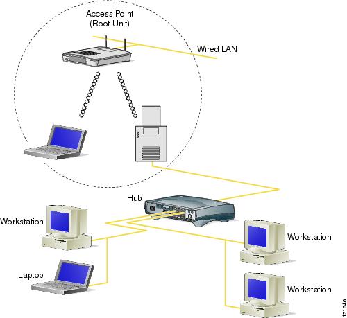
You can configure the wireless device as a root device that is connected to the wired LAN or as a repeater (non-root) device that is not connected to the wired LAN. You can also configure 1100 and 1200 series access points as workgroup bridges. Figure 6-1 shows a root and an access point functioning as a workgroup bridge.
Figure 6-1 Root Access Point and a Workgroup Bridge
See Chapter 18, "Configuring Repeater and Standby Access Points and Workgroup Bridge Mode," for detailed instructions on setting up repeaters.
As a workgroup bridge, an 1100 or a 1200 series access point associates as a client device to an access point or bridge on your network. It provides a network connection to the devices attached to its Ethernet port, usually through a hub or a switch. See Chapter 19, "Configuring Repeater and Standby Access Points and Workgroup Bridge Mode," for detailed instructions on configuring access points as workgroup bridges.
You can also configure a fallback role for root access points. The wireless device automatically assumes the fallback role when its Ethernet port is disabled or disconnected from the wired LAN. There are two possible fallback roles:
•
Repeater—When the Ethernet port is disabled, the wireless device becomes a repeater and associates to a nearby root access point. You do not have to specify a root access point to which the fallback repeater associates; the repeater automatically associates to the root access point that provides the best radio connectivity.
•
Shutdown—the wireless device shuts down its radio and disassociates all client devices.
Beginning in privileged EXEC mode, follow these steps to set the wireless device's radio network role and fallback role:
|
Command
|
Purpose
|
Step 1
|
configure terminal
|
Enter global configuration mode.
|
Step 2
|
interface dot11radio { 0 | 1 }
|
Enter interface configuration mode for the radio interface. The 2.4-GHz radio is radio 0, and the 5-GHz radio is radio 1.
|
Step 3
|
station role repeater | root [ fallback { shutdown | repeater } ] | workgroup-bridge
|
Set the wireless device role.
• Set the role to repeater, root, or workgroup bridge.
Note Workgroup bridge mode is available only on 1100 and 1200 series access points. It is not available on 1130 and 350 series access points.
• (Optional) Select the root access point's fallback role. If the wireless device's Ethernet port is disabled or disconnected from the wired LAN, the wireless device can either shut down its radio port or become a repeater access point associated to any nearby root access point.
|
Step 4
|
end
|
Return to privileged EXEC mode.
|
Step 5
|
copy running-config startup-config
|
(Optional) Save your entries in the configuration file.
|
Configuring Radio Data Rates
You use the data rate settings to choose the data rates the wireless device uses for data transmission. The rates are expressed in megabits per second. The wireless device always attempts to transmit at the highest data rate set to Basic, also called Require on the browser-based interface. If there are obstacles or interference, the wireless device steps down to the highest rate that allows data transmission. You can set each data rate to one of three states:
•
Basic (the GUI labels Basic rates as Required)—Allows transmission at this rate for all packets, both unicast and multicast. At least one of the wireless device's data rates must be set to Basic.
•
Enabled—The wireless device transmits only unicast packets at this rate; multicast packets are sent at one of the data rates set to Basic.
•
Disabled—The wireless device does not transmit data at this rate.
Note
At least one data rate must be set to basic.
You can use the Data Rate settings to set an access point to serve client devices operating at specific data rates. For example, to set the 2.4-GHz radio for 11 megabits per second (Mbps) service only, set the 11-Mbps rate to Basic and set the other data rates to Disabled. To set the wireless device to serve only client devices operating at 1 and 2 Mbps, set 1 and 2 to Basic and set the rest of the data rates to Disabled. To set the 2.4-GHz, 802.11g radio to serve only 802.11g client devices, set any Orthogonal Frequency Division Multiplexing (OFDM) data rate (6, 9, 12, 18, 24, 36, 48, 54) to Basic. To set the 5-GHz radio for 54 Mbps service only, set the 54-Mbps rate to Basic and set the other data rates to Disabled.
You can configure the wireless device to set the data rates automatically to optimize either the range or the throughput. When you enter range for the data rate setting, the wireless device sets the 1 Mbps rate to basic and the other rates to enabled. When you enter throughput for the data rate setting, the wireless device sets all four data rates to basic.
Beginning in privileged EXEC mode, follow these steps to configure the radio data rates:
|
Command
|
Purpose
|
Step 1
|
configure terminal
|
Enter global configuration mode.
|
Step 2
|
interface dot11radio { 0 | 1 }
|
Enter interface configuration mode for the radio interface. The 2.4-GHz radio is radio 0, and the 5-GHz radio is radio 1.
|
Step 3
|
speed
These options are available for the 802.11b, 2.4-GHz radio:
{[1.0] [11.0] [2.0] [5.5] [basic-1.0] [basic-11.0] [basic-2.0] [basic-5.5] | range | throughput}
These options are available for the 802.11g, 2.4-GHz radio:
{[1.0] [2.0] [5.5] [6.0] [9.0] [11.0] [12.0] [18.0] [24.0] [36.0] [48.0] [54.0] [basic-1.0] [basic-2.0] [basic-5.5] [basic-6.0] [basic-9.0] [basic-11.0] [basic-12.0] [basic-18.0] [basic-24.0] [basic-36.0] [basic-48.0] [basic-54.0] | range | throughput [ofdm] | default }
These options are available for the 5-GHz radio:
{[6.0] [9.0] [12.0] [18.0] [24.0] [36.0] [48.0] [54.0] [basic-6.0] [basic-9.0] [basic-12.0] [basic-18.0] [basic-24.0] [basic-36.0] [basic-48.0] [basic-54.0] | range | throughput |default }
|
Set each data rate to basic or enabled, or enter range to optimize range or throughput to optimize throughput.
• (Optional) Enter 1.0, 2.0, 5.5, and 11.0 to set these data rates to enabled on the 802.11b, 2.4-GHz radio.
Enter 1.0, 2.0, 5.5, 6.0, 9.0, 11.0, 12.0, 18.0, 24.0, 36.0, 48.0, and 54.0 to set these data rates to enabled on the 802.11g, 2.4-GHz radio.
Enter 6.0, 9.0, 12.0, 18.0, 24.0, 36.0, 48.0, and 54.0 to set these data rates to enabled on the 5-GHz radio.
• (Optional) Enter basic-1.0, basic-2.0, basic-5.5, and basic-11.0 to set these data rates to basic on the 802.11b, 2.4-GHz radio.
Enter basic-1.0, basic-2.0, basic-5.5, basic-6.0, basic-9.0, basic-11.0, basic-12.0, basic-18.0, basic-24.0, basic-36.0, basic-48.0, and basic-54.0 to set these data rates to basic on the 802.11g, 2.4-GHz radio.
Note The client must support the basic rate that you select or it cannot associate to the wireless device. If you select 12 Mbps or higher for the basic data rate on the 802.11g radio, 802.11b client devices cannot associate to the wireless device's 802.11g radio.
Enter basic-6.0, basic-9.0, basic-12.0, basic-18.0, basic-24.0, basic-36.0, basic-48.0, and basic-54.0 to set these data rates to basic on the 5-GHz radio.
• (Optional) Enter range or throughput to automatically optimize radio range or throughput. When you enter range, the wireless device sets the lowest data rate to basic and the other rates to enabled. When you enter throughput, the wireless device sets all data rates to basic.
(Optional) On the 802.11g radio, enter speed throughput ofdm to set all OFDM rates (6, 9, 12, 18, 24, 36, and 48) to basic (required) and set all the CCK rates (1, 2, 5.5, and 11) to disabled. This setting disables 802.11b protection mechanisms and provides maximum throughput for 802.11g clients. However, it prevents 802.11b clients from associating to the access point.
• (Optional) Enter default to set the data rates to factory default settings (not supported on 802.11b radios).
On the 802.11g radio, the default option sets rates 1, 2, 5.5, and 11 to basic, and rates 6, 9, 12, 18, 24, 36, 48, and 54 to enabled. These rate settings allow both 802.11b and 802.11g client devices to associate to the wireless device's 802.11g radio.
On the 5-GHz radio, the default option sets rates 6.0, 12.0, and 24.0 to basic, and rates 9.0, 18.0, 36.0, 48.0, and 54.0 to enabled.
|
Step 4
|
end
|
Return to privileged EXEC mode.
|
Step 5
|
copy running-config startup-config
|
(Optional) Save your entries in the configuration file.
|
Use the no form of the speed command to remove one or more data rates from the configuration. This example shows how to remove data rates basic-2.0 and basic-5.5 from the configuration:
ap1200# configure terminal
ap1200(config)# interface dot11radio 0
ap1200(config-if)# no speed basic-2.0 basic-5.5
Configuring Radio Transmit Power
Beginning in privileged EXEC mode, follow these steps to set the transmit power on access point radios:
|
Command
|
Purpose
|
Step 1
|
configure terminal
|
Enter global configuration mode.
|
Step 2
|
interface dot11radio { 0 | 1 }
|
Enter interface configuration mode for the radio interface. The 2.4-GHz radio is radio 0, and the 5-GHz radio is radio 1.
|
Step 3
|
power local
These options are available for the 802.11b, 2.4-GHz radio (in mW):
{ 1 | 5 | 20 | 30 | 50 | 100 | maximum }
These options are available for the 5-GHz radio (in mW):
{ 5 | 10 | 20 | 40 | maximum }
If your access point contains an AIR-RM21A 5-GHz radio module, these power options are available (in dBm):
{ -1 | 2 | 5 | 8 | 11 | 14 | 16 | 17 | 20 | maximum }
|
Set the transmit power for the 802.11b, 2.4-GHz radio or the 5-GHz radio to one of the power levels allowed in your regulatory domain.
Note The settings allowed in your regulatory domain might differ from the settings listed here.
|
Step 4
|
power local
These options are available for the 802.11g, 2.4-GHz radio:
power local cck settings:
{ 1 | 5 | 10 | 20 | 30 | 50 | 100 | maximum }
power local ofdm settings:
{ 1 | 5 | 10 | 20 | 30 | maximum }
|
Set the transmit power for the 802.11g, 2.4-GHz radio to one of the power levels allowed in your regulatory domain. All settings are in mW.
On the 2.4-GHz, 802.11g radio, you can set Orthogonal Frequency Division Multiplexing (OFDM) power levels and Complementary Code Keying (CCK) power levels. CCK modulation is supported by 802.11b and 802.11g devices. OFDM modulation is supported by 802.11g and 802.11a devices.
Note The settings allowed in your regulatory domain might differ from the settings listed here.
Note The 802.11g radio transmits at up to 100 mW for the 1, 2, 5.5, and 11Mbps data rates. However, for the 6, 9, 12, 18, 24, 36, 48, and 54Mbps data rates, the maximum transmit power for the 802.11g radio is 30 mW.
|
Step 5
|
end
|
Return to privileged EXEC mode.
|
Step 6
|
copy running-config startup-config
|
(Optional) Save your entries in the configuration file.
|
Use the no form of the power command to return the power setting to maximum, the default setting.
Limiting the Power Level for Associated Client Devices
You can also limit the power level on client devices that associate to the wireless device. When a client device associates to the wireless device, the wireless device sends the maximum power level setting to the client.
Note
Cisco AVVID documentation uses the term Dynamic Transmit Power Control (DTPC) to refer to limiting the power level on associated client devices.
Beginning in privileged EXEC mode, follow these steps to specify a maximum allowed power setting on all client devices that associate to the wireless device:
|
Command
|
Purpose
|
Step 1
|
configure terminal
|
Enter global configuration mode.
|
Step 2
|
interface dot11radio { 0 | 1 }
|
Enter interface configuration mode for the radio interface. The 2.4-GHz radio is radio 0, and the 5-GHz radio is radio 1.
|
Step 3
|
power client
These options are available for 802.11b, 2.4-GHz clients (in mW):
{ 1 | 5 | 20 | 30 | 50 | 100 | maximum}
These options are available for 802.11g, 2.4-GHz clients (in mW):
{ 1 | 5 | 10 | 20 | 30 | 50 | 100 | maximum}
These options are available for 5-GHz clients (in mW):
{ 5 | 10 | 20 | 40 | maximum }
If your access point contains an AIR-RM21A 5-GHz radio module, these power options are available for 5-GHz clients (in dBm):
{ -1 | 2 | 5 | 8 | 11 | 14 | 16 | 17 | 20 | maximum }
|
Set the maximum power level allowed on client devices that associate to the wireless device.
Note The settings allowed in your regulatory domain might differ from the settings listed here.
|
Step 4
|
end
|
Return to privileged EXEC mode.
|
Step 5
|
copy running-config startup-config
|
(Optional) Save your entries in the configuration file.
|
Use the no form of the client power command to disable the maximum power level for associated clients.
Note
Aironet extensions must be enabled to limit the power level on associated client devices. Aironet extensions are enabled by default.
Configuring Radio Channel Settings
The default channel setting for the wireless device radios is least congested; at startup, the wireless device scans for and selects the least-congested channel. For most consistent performance after a site survey, however, we recomend that you assign a static channel setting for each access point. The channel settings on the wireless device correspond to the frequencies available in your regulatory domain. See Appendix A, "Channels and Antenna Settings," for the frequencies allowed in your domain.

Note
Cisco Aironet CB20A client radios sometimes fail to associate to the AIR-RM21A radio module because the CB20A client does not support all the channels supported by the AIR-RM21A radio module. The default channel setting for the AIR-RM21A radio module, least congested, often results in the access point settling on one of these frequencies that the CB20A client radio does not support: channel 149 (5745 GHz), channel 153 (5765 GHz), channel 157 (5785 GHz), and channel 161 (5805 GHz). To avoid this problem, set the channel on the AIR-RM21A radio module to one of the channels supported by the CB20A client.
Each 2.4-GHz channel covers 22 MHz. The bandwidth for channels 1, 6, and 11 does not overlap, so you can set up multiple access points in the same vicinity without causing interference. Both 802.11b and 802.11g 2.4-GHz radios use the same channels and frequencies.
The 5-GHz radio operates on eight channels from 5180 to 5320 MHz. Each channel covers 20 MHz, and the bandwidth for the channels overlaps slightly. For best performance, use channels that are not adjacent (44 and 46, for example) for radios that are close to each other.
Note
Too many access points in the same vicinity creates radio congestion that can reduce throughput. A careful site survey can determine the best placement of access points for maximum radio coverage and throughput.
Beginning in privileged EXEC mode, follow these steps to set the wireless device's radio channel:
|
Command
|
Purpose
|
Step 1
|
configure terminal
|
Enter global configuration mode.
|
Step 2
|
interface dot11radio {0 | 1 }
|
Enter interface configuration mode for the radio interface. The 2.4-GHz radio is radio 0, and the 5-GHz radio is radio 1.
|
Step 3
|
channel frequency | least-congested
|
Set the default channel for the wireless device radio. Table 6-1 and Table 6-2 show the channels and frequencies. To search for the least-congested channel on startup, enter least-congested.
Note The channel command is disabled for 5-GHz radios that comply with European Union regulations on dynamic frequency selection (DFS). See the "DFS Automatically Enabled on Some 5-GHz Radio Channels" section for more information.
|
Step 4
|
end
|
Return to privileged EXEC mode.
|
Step 5
|
copy running-config startup-config
|
(Optional) Save your entries in the configuration file.
|
Table 6-1 shows the available frequencies for the 2.4-GHz radio.
Table 6-1 2.4-GHz Radio Band
Channel
|
Frequency (in MHz)
|
Geographic Location
|
channel 1
|
2412
|
Americas, EMEA, Japan, and China
|
channel 2
|
2417
|
Americas, EMEA, Japan, and China
|
channel 3
|
2422
|
Americas, EMEA, Japan, and China
|
channel 4
|
2427
|
Americas, EMEA, Japan, Israel, and China
|
channel 5
|
2432
|
Americas, EMEA, Japan, Israel, and China
|
channel 6
|
2437
|
Americas, EMEA, Japan, Israel, and China
|
channel 7
|
2442
|
Americas, EMEA, Japan, Israel, and China
|
channel 8
|
2447
|
Americas, EMEA, Japan, Israel, and China
|
channel 9
|
2452
|
Americas, EMEA, Japan, Israel, and China
|
channel 10
|
2457
|
Americas, EMEA, Japan, and China
|
channel 11
|
2462
|
Americas, EMEA, Japan, and China
|
channel 12
|
2467
|
EMEA and Japan only
|
channel 13
|
2472
|
EMEA and Japan only
|
channel 14
|
2484
|
Japan only
|
Table 6-2 shows the available frequencies for the 5-GHz radio.
Table 6-2 5-GHz Radio Band
Channel
|
Frequency (MHz)
|
North America (-A)
|
Taiwan (-T)
|
ETSI
|
Singapore (-S)
|
Japan (-J)
|
34
|
5170
|
—
|
—
|
|
—
|
X
|
36
|
5180
|
X
|
—
|
X
|
X
|
—
|
38
|
5190
|
—
|
—
|
|
—
|
X
|
40
|
5200
|
X
|
—
|
X
|
X
|
—
|
42
|
5210
|
—
|
—
|
|
—
|
X
|
44
|
5220
|
X
|
—
|
X
|
X
|
—
|
46
|
5230
|
—
|
—
|
|
—
|
X
|
48
|
5240
|
X
|
—
|
X
|
X
|
—
|
52
|
5260
|
X
|
X
|
X
|
X
|
—
|
56
|
5280
|
X
|
X
|
X
|
X
|
—
|
60
|
5300
|
X
|
X
|
X
|
X
|
—
|
64
|
5320
|
X
|
X
|
X
|
X
|
—
|
100
|
5500
|
—
|
—
|
X
|
—
|
—
|
104
|
5520
|
—
|
—
|
X
|
—
|
—
|
108
|
5540
|
—
|
—
|
X
|
—
|
—
|
112
|
5560
|
—
|
—
|
X
|
—
|
—
|
116
|
5580
|
—
|
—
|
X
|
—
|
—
|
120
|
5600
|
—
|
—
|
X
|
—
|
—
|
124
|
5620
|
—
|
—
|
X
|
—
|
—
|
128
|
5640
|
—
|
—
|
X
|
—
|
—
|
132
|
5660
|
—
|
—
|
X
|
—
|
—
|
136
|
5680
|
—
|
—
|
X
|
—
|
—
|
140
|
5700
|
—
|
—
|
X
|
—
|
—
|
149
|
5745
|
X
|
—
|
—
|
—
|
—
|
153
|
5765
|
X
|
—
|
—
|
—
|
—
|
157
|
5785
|
X
|
—
|
—
|
—
|
—
|
161
|
5805
|
X
|
—
|
—
|
—
|
—
|
Note
The frequencies allowed in your regulatory domain might differ from the frequencies listed here.
DFS Automatically Enabled on Some 5-GHz Radio Channels
Access points with 5-GHz radios configured at the factory for use in Europe and Singapore now comply with regulations that require radio devices to use Dynamic Frequency Selection (DFS) to detect radar signals and avoid interfering with them. Radios configured for use in other regulatory domains do not use DFS.
When a DFS-enabled 5-GHz radio operates on one of the 15 channels listed in Table 6-3, the access point automatically uses DFS to set the operating frequency.
Note
You cannot manually select a channel for DFS-enabled 5-GHz radios.
Table 6-3 DFS Automatically Enabled on these 5-GHz Channels
5-GHz Channels on Which DFS is Automatically Enabled
|
52 (5260 MHz)
|
104 (5520 MHz)
|
124 (5620 MHz)
|
56 (5280 MHz)
|
108 (5540 MHz)
|
128 (5640 MHz)
|
60 (5300 MHz)
|
112 (5560 MHz)
|
132 (5660 MHz)
|
64 (5320 MHz)
|
116 (5580 MHz)
|
136 (5680 MHz)
|
100 (5500 MHz)
|
120 (5600 MHz)
|
140 (5700 MHz)
|
When DFS is enabled, the access point monitors its operating frequency for radar signals. If it detects radar signals on the channel, the access point takes these steps:
•
Blocks new transmissions on the channel.
•
Flushes the power-save client queues.
•
Broadcasts an 802.11h channel-switch announcement.
•
Disassociates remaining client devices.
•
If participating in WDS, sends a DFS notification to the active WDS device that it is leaving the frequency.
•
Randomly selects a different 5-GHz channel.
•
If the channel selected is one of the channels in Table 6-3, scans the new channel for radar signals for 60 seconds.
•
If there are no radar signals on the new channel, enables beacons and accepts client associations.
•
If participating in WDS, sends a DFS notification of its new operating frequency to the active WDS device.
Note
The maximum legal transmit power is greater for some 5-GHz channels than for others. When it randomly selects a 5-GHz channel on which power is restricted, the access point automatically reduces transmit power to comply with power limits for that channel.
Note
Cisco recommends that you use the world-mode dot11d country-code configuration interface command to configure a country code on DFS-enabled radios. The IEEE 802.11h protocol requires access points to include the country information element (IE) in beacons and probe responses. By default, however, the country code in the IE is blank. You use the world-mode command to populate the country code IE.
Confirming that DFS is Enabled
Use the show controller dot11radio1 command to confirm that DFS is enabled. This example shows a line from the output for the show controller command for a channel on which DFS is enabled:
Current Frequency: 5300 MHz Channel 60 (DFS enabled)
Blocking Channels from DFS Selection
If your regulatory domain limits the channels that you can use in specific locations--for example, indoors or outdoors--you can block groups of channels to prevent the access point from selecting them when DFS is enabled. Use this configuration interface command to block groups of channels from DFS selection:
[no] dfs band [1] [2] [3] [4] block
The 1, 2, 3, and 4 options designate blocks of channels:
•
1—Specifies frequencies 5.150 to 5.250 GHz. This group of frequencies is also known as the UNII-1 band.
•
2—Specifies frequencies 5.250 to 5.350 GHz. This group of frequencies is also known as the UNII-2 band.
•
3—Specifies frequencies 5.470 to 5.725 GHz.
•
4—Specifies frequencies 5.725 to 5.825 GHz. This group of frequencies is also known as the UNII-3 band.
This example shows how to prevent the access point from selecting frequencies 5.150 to 5.350 GHz during DFS:
ap(config-if)# dfs band 1 2 block
This example shows how to unblock frequencies 5.150 to 5.350 for DFS:
ap(config-if)# no dfs band 1 2 block
This example shows how to unblock all frequencies for DFS:
ap(config-if)# no dfs band block
Configuring Location-Based Services
This section describes how to configure location-based services using the access point CLI. As with other access point features, you can use a WLSE on your network to configure LBS on multiple access points. LBS settings do not appear on the access point GUI in this release.
Understanding Location-Based Services
Cisco recommends that you configure a minimum of three access points for LBS. When you configure location-based services (LBS) on your access points, the access points monitor location packets sent by LBS positioning tags attached to assets that you want to track. When an access point receives a positioning packet, it measures the received signal strength indication (RSSI) and creates a UDP packet that contains the RSSI value and the time that the location packet was received. The access point forwards the UDP packets to a location server. The location server calculates the LBS tag's position based on the location information that it receives from the LBS-enabled access points. If your network has a WLSE, the location server can query the WLSE for the status of LBS-enabled access points. Figure 6-2 shows the basic parts of an LBS-enabled network.
Figure 6-2 Basic LBS Network Configuration
The access points that you configure for LBS should be in the same vicinity. If only one or two access points report messages from a tag, the location server can report that the location of the tag is somewhere in the coverage area of the two reporting access points. Consult the documentation for your LBS tags and location server for additional configuration details.
Configuring LBS on Access Points
Use the CLI to configure LBS on your access point. Beginning in privileged EXEC mode, follow these steps to configure LBS:
|
Command
|
Purpose
|
Step 1
|
configure terminal
|
Enter global configuration mode.
|
Step 2
|
dot11 lbs profile-name
|
Create an LBS profile for the access point and enter LBS configuration mode.
|
Step 3
|
server-address ip-address port port
|
Enter the IP address of the location server and the port on the server to which the access point sends UDP packets that contain location information.
|
Step 4
|
method {rssi}
|
(Optional) Select the location method that the access point uses when reporting location information to the location server. In this release, rssi (in which the access point measures the location packet's RSSI) is the only option and is also the default.
|
Step 5
|
packet-type {short | extended}
|
(Optional) Select the packet type that the access point accepts from the LBS tag.
• short—The access point accepts short location packets from the tag. In short packets, the LBS information is missing from the tag packet's frame body and the packet indicates the tag's transmit channel.
• extended—This is the default setting. The access point accepts extended packets from the tag. An extended packet contains two bytes of LBS information in the frame body. If the packet does not contain those two bytes in the frame body, the access point drops the packet.
|
Step 6
|
channel-match
|
(Optional) Specifies that the LBS packet sent by the tag must match the radio channel on which the access point receives the packet. If the channel used by the tag and the channel used by the access point do not match, the access point drops the packet. Channel match is enabled by default.
|
Step 7
|
multicast-address mac-address
|
(Optional) Specifies the multicast address that the tag uses when it sends LBS packets. The default multicast address is 01:40:96:00:00:10.
|
Step 8
|
interface dot11 { 0 | 1 }
|
Specify the radio interface on which this LBS profile is enabled. The 2.4-GHz radio is radio 0, and the 5-GHz radio is radio 1. The profile remains inactive until you enter this command.
|
Step 9
|
exit
|
Return to global configuration mode.
|
In this example, the profile southside is enabled on the access point's 802.11g radio:
ap(config)# dot11 lbs southside
ap(dot11-lbs)# server-address 10.91.105.90 port 1066
ap(dot11-lbs)# interface dot11 0
Enabling and Disabling World Mode
You can configure the wireless device to support 802.11d world mode or Cisco legacy world mode. When you enable world mode, the wireless device adds channel carrier set information to its beacon. Client devices with world mode enabled receive the carrier set information and adjust their settings automatically. For example, a client device used primarily in Japan could rely on world mode to adjust its channel and power settings automatically when it travels to Italy and joins a network there. Cisco client devices running firmware version 5.30.17 or later detect whether the wireless device is using 802.11d or Cisco legacy world mode and automatically use world mode that matches the mode used by the wireless device. World mode is disabled by default.
Beginning in privileged EXEC mode, follow these steps to enable world mode:
|
Command
|
Purpose
|
Step 1
|
configure terminal
|
Enter global configuration mode.
|
Step 2
|
interface dot11radio { 0 | 1}
|
Enter interface configuration mode for the radio interface.
|
Step 3
|
world-mode dot11d country_code code { both | indoor | outdoor } | legacy
|
Enable world mode.
• Enter the dot11d option to enable 802.11d world mode.
– When you enter the dot11d option, you must enter a two-character ISO country code (for example, the ISO country code for the United States is US). You can find a list of ISO country codes at the ISO website.
– After the country code, you must enter indoor, outdoor, or both to indicate the placement of the wireless device.
• Enter the legacy option to enable Cisco legacy world mode.
Note Aironet extensions must be enabled for legacy world mode operation, but Aironet extensions are not required for 802.11d world mode. Aironet extensions are enabled by default.
|
Step 4
|
end
|
Return to privileged EXEC mode.
|
Step 5
|
copy running-config startup-config
|
(Optional) Save your entries in the configuration file.
|
Use the no form of the command to disable world mode.
Disabling and Enabling Short Radio Preambles
The radio preamble (sometimes called a header) is a section of data at the head of a packet that contains information that the wireless device and client devices need when sending and receiving packets. You can set the radio preamble to long or short:
•
Short—A short preamble improves throughput performance. Cisco Aironet Wireless LAN Client Adapters support short preambles. Early models of Cisco Aironet's Wireless LAN Adapter (PC4800 and PC4800A) require long preambles.
•
Long—A long preamble ensures compatibility between the wireless device and all early models of Cisco Aironet Wireless LAN Adapters (PC4800 and PC4800A). If these client devices do not associate to the wireless devices, you should use short preambles.
You cannot configure short or long radio preambles on the 5-GHz radio.
Beginning in privileged EXEC mode, follow these steps to disable short radio preambles:
|
Command
|
Purpose
|
Step 1
|
configure terminal
|
Enter global configuration mode.
|
Step 2
|
interface dot11radio { 0 }
|
Enter interface configuration mode for the 2.4-GHz radio interface.
|
Step 3
|
no preamble-short
|
Disable short preambles and enable long preambles.
|
Step 4
|
end
|
Return to privileged EXEC mode.
|
Step 5
|
copy running-config startup-config
|
(Optional) Save your entries in the configuration file.
|
Short preambles are enabled by default. Use the preamble-short command to enable short preambles if they are disabled.
Configuring Transmit and Receive Antennas
You can select the antenna the wireless device uses to receive and transmit data. There are three options for both the receive and the transmit antenna:
•
Diversity—This default setting tells the wireless device to use the antenna that receives the best signal. If the wireless device has two fixed (non-removeable) antennas, you should use this setting for both receive and transmit.
•
Right—If the wireless device has removable antennas and you install a high-gain antenna on the wireless device's right connector, you should use this setting for both receive and transmit. When you look at the wireless device's back panel, the right antenna is on the right.
•
Left—If the wireless device has removable antennas and you install a high-gain antenna on the wireless device's left connector, you should use this setting for both receive and transmit. When you look at the wireless device's back panel, the left antenna is on the left.
Beginning in privileged EXEC mode, follow these steps to select the antennas the wireless device uses to receive and transmit data:
|
Command
|
Purpose
|
Step 1
|
configure terminal
|
Enter global configuration mode.
|
Step 2
|
interface dot11radio { 0 | 1 }
|
Enter interface configuration mode for the radio interface. The 2.4-GHz radio is radio 0, and the 5-GHz radio is radio 1.
|
Step 3
|
antenna receive {diversity | left | right}
|
Set the receive antenna to diversity, left, or right.
Note For best performance, leave the receive antenna setting at the default setting, diversity.
|
Step 4
|
antenna transmit {diversity | left | right}
|
Set the transmit antenna to diversity, left, or right.
Note For best performance, leave the transmit antenna setting at the default setting, diversity.
|
Step 5
|
end
|
Return to privileged EXEC mode.
|
Step 6
|
copy running-config startup-config
|
(Optional) Save your entries in the configuration file.
|
Disabling and Enabling Aironet Extensions
By default, the wireless device uses Cisco Aironet 802.11 extensions to detect the capabilities of Cisco Aironet client devices and to support features that require specific interaction between the wireless device and associated client devices. Aironet extensions must be enabled to support these features:
•
Load balancing—The wireless device uses Aironet extensions to direct client devices to an access point that provides the best connection to the network based on factors such as number of users, bit error rates, and signal strength.
•
Message Integrity Check (MIC)—MIC is an additional WEP security feature that prevents attacks on encrypted packets called bit-flip attacks. The MIC, implemented on both the wireless device and all associated client devices, adds a few bytes to each packet to make the packets tamper-proof.
•
Cisco Key Integrity Protocol (CKIP)—Cisco's WEP key permutation technique based on an early algorithm presented by the IEEE 802.11i security task group. The standards-based algorithm, TKIP, does not require Aironet extensions to be enabled.
•
Repeater mode—Aironet extensions must be enabled on repeater access points and on the root access points to which they associate.
•
World mode (legacy only)—Client devices with legacy world mode enabled receive carrier set information from the wireless device and adjust their settings automatically. Aironet extensions are not required for 802.11d world mode operation.
•
Limiting the power level on associated client devices—When a client device associates to the wireless device, the wireless device sends the maximum allowed power level setting to the client.
Disabling Aironet extensions disables the features listed above, but it sometimes improves the ability of non-Cisco client devices to associate to the wireless device.
Aironet extensions are enabled by default. Beginning in privileged EXEC mode, follow these steps to disable Aironet extensions:
|
Command
|
Purpose
|
Step 1
|
configure terminal
|
Enter global configuration mode.
|
Step 2
|
interface dot11radio { 0 | 1 }
|
Enter interface configuration mode for the radio interface. The 2.4-GHz radio is radio 0, and the 5-GHz radio is radio 1.
|
Step 3
|
no dot11 extension aironet
|
Disable Aironet extensions.
|
Step 4
|
end
|
Return to privileged EXEC mode.
|
Step 5
|
copy running-config startup-config
|
(Optional) Save your entries in the configuration file.
|
Use the dot11 extension aironet command to enable Aironet extensions if they are disabled.
Configuring the Ethernet Encapsulation Transformation Method
When the wireless device receives data packets that are not 802.3 packets, the wireless device must format the packets to 802.3 using an encapsulation transformation method. These are the two transformation methods:
•
802.1H—This method provides optimum performance for Cisco Aironet wireless products. This is the default setting.
•
RFC1042—Use this setting to ensure interoperability with non-Cisco Aironet wireless equipment. RFC1042 does not provide the interoperability advantages of 802.1H but is used by other manufacturers of wireless equipment.
Beginning in privileged EXEC mode, follow these steps to configure the encapsulation transformation method:
|
Command
|
Purpose
|
Step 1
|
configure terminal
|
Enter global configuration mode.
|
Step 2
|
interface dot11radio { 0 | 1 }
|
Enter interface configuration mode for the radio interface. The 2.4-GHz radio is radio 0, and the 5-GHz radio is radio 1.
|
Step 3
|
payload-encapsulation
snap | dot1h
|
Set the encapsulation transformation method to RFC1042 (snap) or 802.1h (dot1h, the default setting).
|
Step 4
|
end
|
Return to privileged EXEC mode.
|
Step 5
|
copy running-config startup-config
|
(Optional) Save your entries in the configuration file.
|
Enabling and Disabling Reliable Multicast to Workgroup Bridges
The Reliable multicast messages from the access point to workgroup bridges setting limits reliable delivery of multicast messages to approximately 20 Cisco Aironet Workgroup Bridges that are associated to the wireless device. The default setting, disabled, reduces the reliability of multicast delivery to allow more workgroup bridges to associate to the wireless device.
Access points and bridges normally treat workgroup bridges not as client devices but as infrastructure devices, like access points or bridges. Treating a workgroup bridge as an infrastructure device means that the wireless device reliably delivers multicast packets, including Address Resolution Protocol (ARP) packets, to the workgroup bridge.
The performance cost of reliable multicast delivery—duplication of each multicast packet sent to each workgroup bridge—limits the number of infrastructure devices, including workgroup bridges, that can associate to the wireless device. To increase beyond 20 the number of workgroup bridges that can maintain a radio link to the wireless device, the wireless device must reduce the delivery reliability of multicast packets to workgroup bridges. With reduced reliability, the wireless device cannot confirm whether multicast packets reach the intended workgroup bridge, so workgroup bridges at the edge of the wireless device's coverage area might lose IP connectivity. When you treat workgroup bridges as client devices, you increase performance but reduce reliability.

Note
This feature is best suited for use with stationary workgroup bridges. Mobile workgroup bridges might encounter spots in the wireless device's coverage area where they do not receive multicast packets and lose communication with the wireless device even though they are still associated to it.
A Cisco Aironet Workgroup Bridge provides a wireless LAN connection for up to eight Ethernet-enabled devices.
This feature is not supported on the 5-GHz radio.
Beginning in privileged EXEC mode, follow these steps to configure the encapsulation transformation method:
|
Command
|
Purpose
|
Step 1
|
configure terminal
|
Enter global configuration mode.
|
Step 2
|
interface dot11radio { 0 }
|
Enter interface configuration mode for the 2.4-GHz radio interface.
|
Step 3
|
infrastructure-client
|
Enable reliable multicast messages to workgroup bridges.
|
Step 4
|
end
|
Return to privileged EXEC mode.
|
Step 5
|
copy running-config startup-config
|
(Optional) Save your entries in the configuration file.
|
Use the no form of the command to disable reliable multicast messages to workgroup bridges.
Enabling and Disabling Public Secure Packet Forwarding
Public Secure Packet Forwarding (PSPF) prevents client devices associated to an access point from inadvertently sharing files or communicating with other client devices associated to the access point. It provides Internet access to client devices without providing other capabilities of a LAN. This feature is useful for public wireless networks like those installed in airports or on college campuses.
Note
To prevent communication between clients associated to different access points, you must set up protected ports on the switch to which the wireless devices are connected. See the "Configuring Protected Ports" section for instructions on setting up protected ports.
To enable and disable PSPF using CLI commands on the wireless device, you use bridge groups. You can find a detailed explanation of bridge groups and instructions for implementing them in this document:
•
Cisco IOS Bridging and IBM Networking Configuration Guide, Release 12.2. Click this link to browse to the Configuring Transparent Bridging chapter: http://www.cisco.com/en/US/docs/ios/12_2/ibm/configuration/guide/bcftb_external_docbase_0900e4b180753b92_4container_external_docbase_0900e4b180771f88.html
You can also enable and disable PSPF using the web-browser interface. The PSPF setting is on the Radio Settings pages.
PSPF is disabled by default. Beginning in privileged EXEC mode, follow these steps to enable PSPF:
|
Command
|
Purpose
|
Step 1
|
configure terminal
|
Enter global configuration mode.
|
Step 2
|
interface dot11radio { 0 | 1 }
|
Enter interface configuration mode for the radio interface. The 2.4-GHz radio is radio 0, and the 5-GHz radio is radio 1.
|
Step 3
|
bridge-group group port-protected
|
Enable PSPF.
|
Step 4
|
end
|
Return to privileged EXEC mode.
|
Step 5
|
copy running-config startup-config
|
(Optional) Save your entries in the configuration file.
|
Use the no form of the command to disable PSPF.
Configuring Protected Ports
To prevent communication between client devices associated to different access points on your wireless LAN, you must set up protected ports on the switch to which the wireless devices are connected.
Beginning in privileged EXEC mode, follow these steps to define a port on your switch as a protected port:
|
Command
|
Purpose
|
Step 1
|
configure terminal
|
Enter global configuration mode.
|
Step 2
|
interface interface-id
|
Enter interface configuration mode, and enter the type and number of the switchport interface to configure, such as gigabitethernet0/1.
|
Step 3
|
switchport protected
|
Configure the interface to be a protected port.
|
Step 4
|
end
|
Return to privileged EXEC mode.
|
Step 5
|
show interfaces interface-id switchport
|
Verify your entries.
|
Step 6
|
copy running-config startup-config
|
(Optional) Save your entries in the configuration file.
|
To disable protected port, use the no switchport protected interface configuration command.
For detailed information on protected ports and port blocking, refer to the "Configuring Port-Based Traffic Control" chapter in the Catalyst 3550 Multilayer Switch Software Configuration Guide, 12.1(12c)EA1. Click this link to browse to that guide:
http://www.cisco.com/en/US/docs/switches/lan/catalyst3550/software/release/12.1_12c_ea1/configuration/guide/swtrafc.html
Configuring the Beacon Period and the DTIM
The beacon period is the amount of time between access point beacons in Kilomicroseconds. One Kµsec equals 1,024 microseconds. The Data Beacon Rate, always a multiple of the beacon period, determines how often the beacon contains a delivery traffic indication message (DTIM). The DTIM tells power-save client devices that a packet is waiting for them.
For example, if the beacon period is set at 100, its default setting, and the data beacon rate is set at 2, its default setting, then the wireless device sends a beacon containing a DTIM every 200 Kµsecs. One Kµsec equals 1,024 microseconds.
The default beacon period is 100, and the default DTIM is 2. Beginning in privileged EXEC mode, follow these steps to configure the beacon period and the DTIM:
|
Command
|
Purpose
|
Step 1
|
configure terminal
|
Enter global configuration mode.
|
Step 2
|
interface dot11radio { 0 | 1 }
|
Enter interface configuration mode for the radio interface. The 2.4-GHz radio is radio 0, and the 5-GHz radio is radio 1.
|
Step 3
|
beacon period value
|
Set the beacon period. Enter a value in Kilomicroseconds.
|
Step 4
|
beacon dtim-period value
|
Set the DTIM. Enter a value in Kilomicroseconds.
|
Step 5
|
end
|
Return to privileged EXEC mode.
|
Step 6
|
copy running-config startup-config
|
(Optional) Save your entries in the configuration file.
|
Configure RTS Threshold and Retries
The RTS threshold determines the packet size at which the wireless device issues a request to send (RTS) before sending the packet. A low RTS Threshold setting can be useful in areas where many client devices are associating with the wireless device, or in areas where the clients are far apart and can detect only the wireless device and not each other. You can enter a setting ranging from 0 to 2347 bytes.
Maximum RTS retries is the maximum number of times the wireless device issues an RTS before stopping the attempt to send the packet over the radio. Enter a value from 1 to 128.
The default RTS threshold is 2347, and the default maximum RTS retries setting is 32. Beginning in privileged EXEC mode, follow these steps to configure the RTS threshold and maximum RTS retries:
|
Command
|
Purpose
|
Step 1
|
configure terminal
|
Enter global configuration mode.
|
Step 2
|
interface dot11radio { 0 | 1 }
|
Enter interface configuration mode for the radio interface. The 2.4-GHz radio is radio 0, and the 5-GHz radio is radio 1.
|
Step 3
|
rts threshold value
|
Set the RTS threshold. Enter an RTS threshold from 0 to 2347.
|
Step 4
|
rts retries value
|
Set the maximum RTS retries. Enter a setting from 1 to 128.
|
Step 5
|
end
|
Return to privileged EXEC mode.
|
Step 6
|
copy running-config startup-config
|
(Optional) Save your entries in the configuration file.
|
Use the no form of the command to reset the RTS settings to defaults.
Configuring the Maximum Data Retries
The maximum data retries setting determines the number of attempts the wireless device makes to send a packet before giving up and dropping the packet.
The default setting is 32. Beginning in privileged EXEC mode, follow these steps to configure the maximum data retries:
|
Command
|
Purpose
|
Step 1
|
configure terminal
|
Enter global configuration mode.
|
Step 2
|
interface dot11radio { 0 | 1 }
|
Enter interface configuration mode for the radio interface. The 2.4-GHz radio is radio 0, and the 5-GHz radio is radio 1.
|
Step 3
|
packet retries value
|
Set the maximum data retries. Enter a setting from 1 to 128.
|
Step 4
|
end
|
Return to privileged EXEC mode.
|
Step 5
|
copy running-config startup-config
|
(Optional) Save your entries in the configuration file.
|
Use the no form of the command to reset the setting to defaults.
Configuring the Fragmentation Threshold
The fragmentation threshold determines the size at which packets are fragmented (sent as several pieces instead of as one block). Use a low setting in areas where communication is poor or where there is a great deal of radio interference.
The default setting is 2338 bytes. Beginning in privileged EXEC mode, follow these steps to configure the fragmentation threshold:
|
Command
|
Purpose
|
Step 1
|
configure terminal
|
Enter global configuration mode.
|
Step 2
|
interface dot11radio { 0 | 1 }
|
Enter interface configuration mode for the radio interface. The 2.4-GHz radio is radio 0, and the 5-GHz radio is radio 1.
|
Step 3
|
fragment-threshold value
|
Set the fragmentation threshold. Enter a setting from 256 to 2346 bytes for the 2.4-GHz radio. Enter a setting from 256 to 2346 bytes for the 5-GHz radio.
|
Step 4
|
end
|
Return to privileged EXEC mode.
|
Step 5
|
copy running-config startup-config
|
(Optional) Save your entries in the configuration file.
|
Use the no form of the command to reset the setting to defaults.
Enabling Short Slot Time for 802.11g Radios
You can increase throughput on the 802.11g, 2.4-GHz radio by enabling short slot time. Reducing the slot time from the standard 20 microseconds to the 9-microsecond short slot time decreases the overall backoff, which increases throughput. Backoff, which is a multiple of the slot time, is the random length of time that a station waits before sending a packet on the LAN.
Many 802.11g radios support short slot time, but some do not. When you enable short slot time, the wireless device uses the short slot time only when all clients associated to the 802.11g, 2.4-GHz radio support short slot time.
Short slot time is supported only on the 802.11g, 2.4-GHz radio. Short slot time is disabled by default.
In radio interface mode, enter this command to enable short slot time:
ap(config-if)# slot-time-short
Enter no slot-time-short to disable short slot time.
Performing a Carrier Busy Test
You can perform a carrier busy test to check the radio activity on wireless channels. During the carrier busy test, the wireless device drops all associations with wireless networking devices for 4 seconds while it conducts the carrier test and then displays the test results.
In privileged EXEC mode, enter this command to perform a carrier busy test:
dot11 interface-number carrier busy
For interface-number, enter dot11radio 0 to run the test on the 2.4-GHz radio, or enter dot11radio 1 to run the test on the 5-GHz radio.
Use the show dot11 carrier busy command to re-display the carrier busy test results.