-
Cisco SPA232D Mobility Enhanced Phone Adapter Administration Guide (HTML)
-
Getting Started - Feature Overview
-
Getting Started - Feature Overview
-
Getting Started - Hardware and Installation
-
Getting Started - Wall Mounting, IVR, and GUI Overview
-
Quick Setup for Voice over IP Service
-
Configuring the Network
-
Configuring the Voice Settings
-
Administration Settings
-
Viewing Status and Statistics
-
Frequently Asked Questions
-
Using the IVR for Administration
-
Advanced Options for Voice Services
-
Where To Go From Here
-
 Feedback
Table Of Contents
Configuration and Management of the ATA
Registering a Cisco SPA302D Handset
Using the IVR for Administration
Before You Begin
Before you begin the installation, make sure that you have the following equipment and services:
•
An active Internet account and Voice over IP account
•
•
•
•
•
Product Features
Top Panel
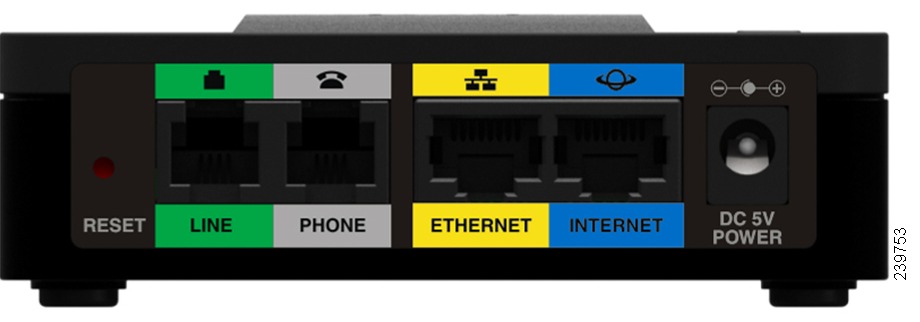
Back Panel
Default Settings
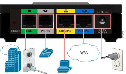
Connecting the Equipment
NOTE
STEP 1
STEP 2
STEP 3
STEP 4
STEP 5
Configuration and Management of the ATA
You can use the web-based configuration utility to set up your ATA. You also can use the built-in Interactive Voice Response (IVR) system. (See Using the IVR for Administration.)
STEP 1
STEP 2
NOTE: Make sure your computer's Ethernet adapter is set to obtain an IP address automatically (DHCP). For more information, refer to the Help for your operating system.
STEP 3
STEP 4
Note: 192.168.15.1 is the default local IP address of the ATA.STEP 5
NOTE: A user account allows access to limited settings and status pages. To log in as a user, enter cisco as the username and the password.
STEP 6
Your VoIP service may require only a few basic parameters to successfully register the Cisco SPA232D. The Quick Setup page offers a shortcut to enter the basic parameters. For a more comprehensive listing of parameters, choose the Voice menu, and then use the links in the navigation tree.
•
•
•
•
•
Note: The Cisco SPA232D assigns DECT Line 1 as the default line for outgoing calls from Cisco SPA302D handsets. If needed, you can configure additional VoIP accounts as separate "DECT Lines." To do so, choose the Voice menu, and then use the DECT Line 1~10 links in the navigation tree. Use the check boxes on the Quick Setup page to associate the DECT Line(s) to each handset.
STEP 7
STEP 8
Registering a Cisco SPA302D Handset
You can register Cisco SPA302D handsets to the integrated DECT base station. These handsets can be purchased separately.
STEP 1
STEP 2
STEP 3
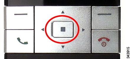
Using the navigation arrows, scroll to the Settings icon and press the center navigation button to select it.
STEP 4
STEP 5
TIP: If you press the button for fewer than seven seconds, the green status light flashes slowly, indicating the unit is in "paging" mode and is not in registration mode. Registration will not work if the unit is in paging mode.
STEP 6
STEP 7
Additional Information
Using the IVR for Administration
An IVR system is available to help you to configure and manage your ATA. You can use the telephone keypad to select options and to make your entries.
To access the IVR menu:
STEP 1
STEP 2
STEP 3
STEP 4
TIPS:
•
•
•
•
•
•
•
–
–
–
IVR Actions
Mounting the ATA
You can place the ATA on a desktop or mount it on a wall.
CAUTION
Desktop Placement
Place the ATA on a flat surface near an electrical outlet.
WARNINGWall Mounting
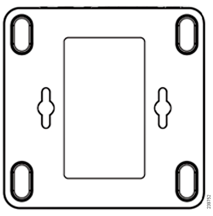
The ATA has two wall-mount slots on the bottom panel. To mount the ATA on a wall, you need mounting hardware (not included). Suggested hardware is illustrated (not true to scale).
Recommended hardware (not included): Two number-six pan-head tapping screws, 5/8-in. length, with anchors for sheet rock installation.
WARNINGTo mount the unit to the wall:
STEP 1
STEP 2
STEP 3
STEP 4