-
Cisco SPA232D Mobility Enhanced Phone Adapter Administration Guide (HTML)
-
Getting Started - Feature Overview
-
Getting Started - Feature Overview
-
Getting Started - Hardware and Installation
-
Getting Started - Wall Mounting, IVR, and GUI Overview
-
Quick Setup for Voice over IP Service
-
Configuring the Network
-
Configuring the Voice Settings
-
Administration Settings
-
Viewing Status and Statistics
-
Frequently Asked Questions
-
Using the IVR for Administration
-
Advanced Options for Voice Services
-
Where To Go From Here
-
 Feedback
Table Of Contents
Advanced Options for Voice Services
Optimizing Fax Completion Rates
VoIP-to-PSTN and PSTN-to-VoIP Calling
Configuring VoIP Failover to PSTN
Sharing One VoIP Account Between the PHONE and LINE Ports
PSTN to VoIP Call with and Without Ring-Thru
VoIP to PSTN Call With and Without Authentication
Using HTTP Digest Authentication
Call Forwarding to PSTN Gateway
Forward-On-No-Answer to the PSTN Gateway
Forward-All to the PSTN gateway
Forward to a Particular PSTN Number
Forward-On-Busy to PSTN Gateway or Number
Acceptance and Transmission of the Dialed Digits
Dial Plan Timer (Off-Hook Timer)
Interdigit Long Timer (Incomplete Entry Timer)
Interdigit Short Timer (Complete Entry Timer)
Advanced Options for Voice Services
This appendix provides additional information about configuring advanced options for voice services.
STEP 1

•
•
Optimizing Fax Completion Rates
Issues can occur with fax transmissions over IP networks, even with the T.38 standard, which is supported by the ATA. You can adjust several settings on your ATA to optimize your fax completion rates.
STEP 1
•
•
STEP 2
STEP 3
•
•
STEP 4
•
•
STEP 5
•
•
•
•
•
STEP 6
STEP 7
modem passthrough nse payload-type 110 codec g711ulaw
fax rate disable
fax protocol pass-through g711ulawNote: If a T.38 call cannot be set-up, then the call automatically reverts to G.711 fallback.
STEP 8
fax protocol T38
fax rate voice
fax-relay ecm disable
fax nsf 000000
no vadFax Troubleshooting
If you have problems sending or receiving faxes, complete the following steps:
STEP 1
STEP 2
STEP 3
STEP 4
STEP 5
a.
http://<ATA_Local_IP_Address>/admin/config.xml&xuser=<admin_user>&xpassword=<admin_password>b.
STEP 6
NOTE: You can also capture data using a sniffer trace.
STEP 7
STEP 8
•
•
VoIP-to-PSTN and PSTN-to-VoIP Calling
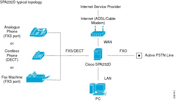
The ATA allows calls to be made by using SIP-based Voice-over-IP (VoIP) services and traditional telephone Public Switched Telephone Network (PSTN) services. Calls can be placed and received by using an analog phone or fax machine and Cisco SPA302D Mobility Enhanced Cordless Telephone Handsets.
The ATA maintains the state of each call and makes the proper reaction to user input events (such as on/off hook or hook flash). Because the ATA uses the Session Initiation Protocol (SIP), it is compatible with most Internet Telephony Service Provider (ITSP) offerings.
How VoIP-To-PSTN Calls Work
To obtain PSTN services through the Cisco SPA302D, the VoIP caller establishes a connection with the PSTN Line by way of a standard SIP INVITE request addressed to the PSTN Line.
One-Stage Dialing
One-stage dialing allows a call to be started over VoIP and then immediately get a dial tone on the PSTN. When you take a phone off hook and dial a number, the call is automatically routed to the VoIP or the PSTN, based on the dial plan.
Optionally, you can enable HTTP Digest Authentication. In this case, the ATA challenges the INVITE with a 401 response if it does not have a valid Authorization header. The Authorization header should include a <User ID n> parameter, where n refers to one of eight VoIP user accounts that can be configured on the ATA device. The credentials are computed based on the corresponding password using Message Digest 5 (MD5). The <User ID n> parameter must match one of the VoIP accounts stored on the ATA device. You can configure these settings on the PSTN (LINE Port) page.
Two-Stage Dialing
In two-stage dialing, the LINE port goes off-hook but does not automatically dial any digits after accepting the call. To invoke two-stage dialing, the VoIP caller should INVITE the PSTN line without the user-id in the Request-URI or with a user-id that matches exactly the <User ID n> of the PSTN Line. A different user-id in the Request-URI is treated as a request for one-stage dialing if one-stage dialing is enabled, or dropped by the ATA (as if no user-id is given) if one-stage dialing is disabled.
HTTP Digest Authentication can be also used for two-stage dialing, as in one-stage dialing. If using HTTP Digest Authentication or Authentication is disabled, the VoIP caller should hear the PSTN dial tone right after the call is answered (by a SIP 200 response).
You also can enable PIN authentication. In this case, the VoIP caller is prompted to enter a PIN number after the ATA answers the call. The PIN number must end with a # key. The inter-PIN-digit timeout is 10 seconds (not configurable). Up to eight VoIP caller PIN numbers can be configured on the ATA. A dial plan can be selected for each PIN number. If the caller enters a wrong PIN or the ATA times out waiting for more PIN digits, the ATA tears down the call immediately with a BYE request.
The call scenarios may involve the following types of callers:
•
•
•
VoIP callers can be authenticated by one of the following methods:
•
•
•
PSTN callers can be authenticated by one of the following methods:
•
•
NOTE
You can configure these settings in the VoIP-To-PSTN Gateway Setup section of the PSTN (LINE Port) page.
How PSTN-To-VoIP Calls Work
For PSTN-to-VoIP calls, the basic PSTN-to-VoIP call flow is as follows:
1.
2.
3.
You can add PIN authentication to the basic flow:
1.
2.
3.
•
•
NOTE
Terminating Gateway Calls
There are two call legs in a PSTN gateway call: the PSTN call leg and the VoIP call leg. A gateway call is terminated when either call leg is ended. When the call terminates, the LINE port goes on-hook so the PSTN line is available for use. The ATA detects that the PSTN call leg is ended when one of the following conditions occurs during a call:
•
•
•
When any of the above conditions occur, the ATA takes the LINE port on hook and sends a BYE request to end the VoIP call leg. On the other hand, when the ATA device receives a SIP BYE from the VoIP during a call, it takes the LINE port on hook to end the PSTN call leg.
In addition, the ATA device can also send a refresh signal periodically to the VoIP call leg to determine whether the call leg is still up. If a refresh operation fails, the ATA device ends both call legs.
You can configure these settings in the PSTN Disconnect Detection section of the PSTN (LINE Port) page.
VoIP Outbound Call Routing
Calls made from Line 1 are routed through the configured Line 1 service provider, by default. You can override this behavior by IP dialing, through which the calls can be routed to any IP address that the user enters. The ATA allows flexible call routing with four sets of gateway parameters and configurable dial plans. You can configure this feature in the Gateway Accounts section of the Line 1 Settings (PHONE Port) page.
You can specify Gateways 1 to 4 in a dial plan by using the identifiers gw1, gw2, gw3, or gw4. Also, gw0 represents the internal PSTN gateway via the LINE port. You can specify in the dial plan to use gwx (x = 0,1,2,3,4) when making certain calls. In general, you can specify any gateway address in the dial plan. In addition, three parameters are added that can be used with call routing:
•
•
•
The following table lists some examples.
You can set up multiple PSTN gateways at different locations and configure Line 1 to use a different gateway when dialing specific numbers.
Configuring VoIP Failover to PSTN
When power is disconnected from the ATA, the FXS port is connected to the LINE port. In this case, the telephone attached to the FXS port is electrically connected to the PSTN service via the LINE port. When power is applied to the ATA device, the FXS port is disconnected from the LINE port. However, if the PSTN line is in use when the power is applied to the ATA device, the relay is not flipped until the PSTN line is released. This feature ensures that the ATA device does not interrupt any call in progress on the PSTN line.
When Line 1 VoIP service is down (because of registration failure or loss of network link), the ATA device can be configured to automatically route all outbound calls to the internal gateway using the parameter listed below.
You can configure this setting on the Voice > Line 1 page.
Sharing One VoIP Account Between the PHONE and LINE Ports
Both the PHONE port (Line 1) and LINE port (PSTN) can receive incoming calls for a single VoIP account. Consider the following points:
•
•
•
•
•
PSTN Call to Ring Line 1
This feature allows a PSTN caller to ring Line 1. When the PSTN line rings, the PSTN Line makes a local VoIP call to Line 1. If Line 1 is busy, it stops. After a given number of rings, the VoIP gateway picks up the call.
Symmetric RTP
The Symmetric RTP parameter is used to send audio RTP to the source IP and port of the inbound RTP packets. This facilitates NAT traversal. You can configure these settings in the SIP Parameters section of the SIP page.
Call Progress Tones
The ATA has configurable call progress tones. Call progress tones are generated locally on the ATA, so an end user is advised of status (such as ringback). Parameters for each type of tone (for instance a dial tone played back to an end user) may include the following specifications:
•
•
•
When one VoIP account is shared between the FXS and PSTN Lines, the following parameters are recommended to be set. You can configure these settings on the Regional page.
Call Scenarios
This section describes some typical scenarios where the ATA device can be applied. Some terms are introduced in the first few sections and reused in later sections. This section includes the following topics:
•
•
•
PSTN to VoIP Call with and Without Ring-Thru
The PSTN caller calls the PSTN line connected to the LINE port. Ring-Thru is disabled. After the call rings for a delay equal to the value in PSTN Answer Delay, the VoIP gateway answers the call and prompts the PSTN caller to enter a PIN number (assuming PIN authentication is enabled). After a valid PIN is entered, the caller is prompted to dial the VoIP number. A dial plan is selected according to the PIN number entered by the caller. If authentication is disabled, the default PSTN dial plan is used. Note than the dial plan choice cannot be 0 for a PSTN caller.
NOTE
The same scenario can be implemented using Ring-Thru. When the PSTN line rings, Line 1 rings also. This feature is called Ring-Thru. If Line 1 is picked up before the VoIP gateway auto-answers, it is connected to the PSTN call. Line 1 hears a call waiting tone if it is already connected to another call.
VoIP to PSTN Call With and Without Authentication
This section describes three scenarios with and without authentication and includes the following topics:
•
Using PIN Authentication
This scenario assumes that the PSTN Line has a different VoIP account than the Line 1 account. The VoIP caller calls the FXO number, which auto-answers after VoIP Answer Delay. The ATA device then prompts the VoIP caller for a PIN. When a valid PIN is entered, the ATA plays the Outside Dial Tone and prompts the caller to dial the PSTN number.
The number dialed is processed by the dial plan corresponding to the VoIP caller. If the dial plan choice is 0, no dial plan is needed and the user hears the PSTN dial tone right after the PIN is entered. If the dial plan choice is not 0, the final number returned from the dial plan after the complete number is dialed by the caller is dialed to the PSTN. The caller does not hear the PSTN dial tone (except for a little leakage before the first digit of the final number is auto-dialed by the ATA device).
If the PSTN Line is busy (off-hook, ringing, or PSTN line not connected) when the VoIP caller calls, the ATA device replies with 503. If the PIN number is invalid or entered after the VoIP call leg is connected, the ATA device plays the reorder tone to the VoIP caller and eventually ends the call when the reorder tone times out.
NOTE
Using HTTP Digest Authentication
The same scenario can be implemented with HTTP digest authentication when the calling device supports the configuration of a auth-ID and password to access the ATA device PSTN gateway. When the VoIP caller calls the PSTN Line, the ATA device challenges the INVITE request with a 401 response. The calling device should then provide the correct credentials in a subsequent retry of the INVITE, computed with the auth-ID and password using MD5.
If the credentials are correct, the target number specified in the user-id field of the INVITE Request-URI is processed by the dial plan corresponding to the VoIP user (assuming the dial plan choice is not 0). The final number is then auto-dialed by the ATA device.
If the credentials are incorrect, the ATA device challenges the INVITE again. If the auth-ID does not exist in the ATA device configuration, the ATA device replies 403 to the INVITE. If the target number is invalid according to the corresponding dial plan, the ATA device also replies 403 to the INVITE. Again, if the PSTN Line is busy at the time of the call, the ATA device replies 503.
NOTE
Without Authentication
This scenario can also be implemented without authentication, using one-stage or two-stage dialing, as in the HTTP Authentication case. The default VoIP caller dial plan is used in this scenario. Authentication is performed when the method is none or when the source IP address of the inbound INVITE matches one of the VoIP Access List patterns.
Call Forwarding to PSTN Gateway
This section describes a number of scenarios that forward calls to the PSTN gateway. It includes the following topics:
•
•
•
•
You can configure Call Forward settings on the User 1 page.
Forward-On-No-Answer to the PSTN Gateway
In this scenario, Line 1 is configured to Cfwd No Ans Dest to the PSTN Gateway. The scenario is implemented by setting User 1 to forward to gw0 on no answer, with Cfwd No Ans Delay set to six seconds.
The caller calls Line 1 and if Line 1 is not picked up after six seconds, the PSTN Line picks up the call and the call reverts to a PSTN-Gateway call, as described above. In this case, HTTP authentication is not allowed because Line 1 does not authenticate inbound INVITE requests. If you need to authenticate the VoIP caller in this case, you must select the PIN authentication method, or else the caller is not authenticated.
NOTE
Forward-All to the PSTN gateway
In this scenario, Line 1 is configured with Cfwd All Dest parameter to the PSTN gateway.This scenario is the same the previous case, except the FXO picks up the Line 1 call immediately.
If the PSTN Line is busy at the moment of the call, the PSTN Line does not pick up the call, the call forward rule is ignored, and Line 1 continues to ring.
Forward to a Particular PSTN Number
In this scenario, the forward destination is set to <target-number>@gw0>. This is the same as in the previous examples, except that the ATA device automatically dials the given target number on the PSTN line right after it answers the VoIP call leg. This is a special case of one-stage dialing where the target number is specified in the configuration. The caller is not authenticated in this case regardless of the authentication method. However, the caller is still limited by the VoIP Caller ID Pattern parameter
Forward-On-Busy to PSTN Gateway or Number
This scenario is similar to the previous cases of call forwarding to gw0, but this applies when Line 1 is active.
Configuring Dial Plans
Dial plans determine how dialed digits are interpreted and transmitted. They also determine whether the dialed number is accepted or rejected. You can use a dial plan to facilitate dialing or to block certain types of calls such as long distance or international. This section includes information that you need to understand dial plans, as well as procedures for configuring your own dial plans.
To edit a dial plan, click Voice on the menu bar, and then click Line 1 or Line 2 in the navigation tree. Scroll down to the Dial Plan section, and then enter the digit sequences in the Dial Plan field. For more information and examples, see the following topics:
•
•
•
•
Digit Sequences
A dial plan contains a series of digit sequences, separated by the pipe character: |
The entire collection of sequences is enclosed within parentheses. Each digit sequence within the dial plan includes a series of elements, which are individually matched to the keys that the user presses.
NOTE
Digit Sequence Examples
The following examples show digit sequences that you can enter in a dial plan.
In a complete dial plan entry, sequences are separated by a pipe character (|), and the entire set of sequences is enclosed within parentheses.
EXAMPLE: ([1-8]xx | 9, xxxxxxx | 9, <:1>[2-9]xxxxxxxxx | 8, <:1212>xxxxxxx |
9, 1 [2-9] xxxxxxxxx | 9, 1 900 xxxxxxx ! | 9, 011xxxxxx. | 0 | [49]11 )
NOTE
•
( [1-8]xx | 9, xxxxxxx | 9, <:1>[2-9]xxxxxxxxx | 8, <:1212>xxxxxxx | 9, 1 [2-9] xxxxxxxxx | 9, 1 900 xxxxxxx ! | 9, 011xxxxxx. | 0 | [49]11 )
[1-8]xx Allows a user dial any three-digit number that starts with the digits 1 through 8. If your system uses four-digit extensions, you would instead enter the following string: [1-8]xxx
•
( [1-8]xx | 9, xxxxxxx | 9, <:1>[2-9]xxxxxxxxx | 8, <:1212>xxxxxxx | 9, 1 [2-9] xxxxxxxxx | 9, 1 900 xxxxxxx ! | 9, 011xxxxxx. | 0 | [49]111)
9, xxxxxxx After a user presses 9, an external dial tone sounds. The user can then dial any seven-digit number, as in a local call.
•
( [1-8]xx | 9, xxxxxxx | 9, <:1>[2-9]xxxxxxxxx | 8,<:1212>xxxxxxx | 9, 1 [2-9] xxxxxxxxx | 9, 1 900 xxxxxxx !| 9, 011xxxxxx. | 0 | [49]11 )
9, <:1>[2-9]xxxxxxxxx This example is useful where a local area code is required. After a user presses 9, an external dial tone sounds. The user must enter a 10-digit number that begins with a digit 2 through 9. The system automatically inserts the 1 prefix before transmitting the number to the carrier.
•
( [1-8]xx | 9, xxxxxxx | 9, <:1>[2-9]xxxxxxxxx | 8, <:1212>xxxxxxx | 9, 1 [2-9] xxxxxxxxx | 9, 1 900 xxxxxxx ! | 9, 011xxxxxx. | 0 | [49]11 )
8, <:1212>xxxxxxx This is example is useful where a local area code is required by the carrier but the majority of calls go to one area code. After the user presses 8, an external dial tone sounds. The user can enter any seven-digit number. The system automatically inserts the 1 prefix and the 212 area code before transmitting the number to the carrier.
•
( [1-8]xx | 9, xxxxxxx | 9, <:1>[2-9]xxxxxxxxx |8, <:1212>xxxxxxx | 9, 1 [2-9] xxxxxxxxx | 9, 1 900 xxxxxxx ! | 9,011xxxxxx. | 0 | [49]11 )
9, 1 [2-9] xxxxxxxxx After the user presses 9, an external dial tone sounds. The user can enter any 11-digit number that starts with 1 and is followed by a digit 2 through 9.
•
( [1-8]xx | 9, xxxxxxx | 9, <:1>[2-9]xxxxxxxxx |8, <:1212>xxxxxxx | 9, 1 [2-9] xxxxxxxxx | 9, 1 900 xxxxxxx ! |9, 011xxxxxx. | 0 | [49]11 )
9, 1 900 xxxxxxx ! This digit sequence is useful if you want to prevent users from dialing numbers that are associated with high tolls or inappropriate content, such as 1-900 numbers in the United States. After the user press 9, an external dial tone sounds. If the user enters an 11-digit number that starts with the digits 1900, the call is rejected.
•
( [1-8]xx | 9, xxxxxxx | 9, <:1>[2-9]xxxxxxxxx | 8, <:1212>xxxxxxx | 9, 1 [2-9] xxxxxxxxx | 9, 1 900 xxxxxxx ! | 9, 011xxxxxx. | 0 | [49]11 )
9, 011xxxxxx. After the user presses 9, an external dial tone sounds. The user can enter any number that starts with 011, as in an international call from the United States.
•
( [1-8]xx | 9, xxxxxxx | 9, <:1>[2-9]xxxxxxxxx | 8, <:1212>xxxxxxx | 9, 1 [2-9] xxxxxxxxx | 9, 1 900 xxxxxxx ! | 9, 011xxxxxx. | 0 | [49]11 )
0 | [49]11 This example includes two digit sequences, separated by the pipe character. The first sequence allows a user to dial 0 for an operator. The second sequence allows the user to enter 411 for local information or 911 for emergency services.Acceptance and Transmission of the Dialed Digits
When a user dials a series of digits, each sequence in the dial plan is tested as a possible match. The matching sequences form a set of candidate digit sequences. As more digits are entered by the user, the set of candidates diminishes until only one or none are valid. When a terminating event occurs, the ATA either accepts the user-dialed sequence and initiates a call, or else rejects the sequence as invalid. The user hears the reorder (fast busy) tone if the dialed sequence is invalid.
The following table explains how terminating events are processed.
Dial Plan Timer (Off-Hook Timer)
You can think of the Dial Plan Timer as "the off-hook timer." This timer starts counting when the phone goes off hook. If no digits are dialed within the specified number of seconds, the timer expires and the null entry is evaluated. Unless you have a special dial plan string to allow a null entry, the call is rejected. Default setting: 5
Syntax for the Dial Plan Timer
(Ps<:n> | dial plan )•
•
Examples for the Dial Plan Timer
NOTE
•
(P9 | (9,8<:1408>[2-9]xxxxxx | 9,8,1[2 9]xxxxxxxxx | 9,8,011xx. | 9,8,xx.|[1-8]xx)
P9 After taking a phone off hook, a user has 9 seconds to begin dialing. If no digits are pressed within 9 seconds, the user hears a reorder (fast busy) tone. By setting a longer timer, you allow more time for users to enter the digits.
xx This code allows the entry of one or more digits. Do not use a single x, allowing 0 or more digits. This setting will produce unwanted results especially if you are deploying timers.•
(P9<:23> | (9,8<:1408>[2-9]xxxxxx | 9,8,1[2-9]xxxxxxxxx | 9,8,011xx. | 9,8,xx.|[1-8]xx)
P9<:23> After taking the phone off hook, a user has 9 seconds to begin dialing. If no digits are pressed within 9 seconds, the call is transmitted automatically to extension 23.
•
(P0 <:1000>)
With the timer set to 0 seconds, the call is transmitted automatically to the specified extension when the phone goes off hook.Interdigit Long Timer (Incomplete Entry Timer)
You can think of this timer as the "incomplete entry" timer. This timer measures the interval between dialed digits. It applies as long as the dialed digits do not match any digit sequences in the dial plan. Unless the user enters another digit within the specified number of seconds, the entry is evaluated as incomplete, and the call is rejected. Default setting: 10 seconds
NOTE
Syntax for the Interdigit Long Timer
L:s, ( dial plan )
s: The number of seconds; if no number is entered after L:, the default timer of 5 seconds applies. The timer sequence appears to the left of the initial parenthesis for the dial plan.
Example for the Interdigit Long Timer
L:15, (9,8<:1408>[2-9]xxxxxx | 9,8,1[2-9]xxxxxxxxx | 9,8,011xx. | 9,8,xx.|[1-8]xx)
L:15, This dial plan allows the user to pause for up to 15 seconds between digits before the Interdigit Long Timer expires.
Interdigit Short Timer (Complete Entry Timer)
You can think of this timer as the "complete entry" timer. This timer measures the interval between dialed digits. It applies when the dialed digits match at least one digit sequence in the dial plan. Unless the user enters another digit within the specified number of seconds, the entry is evaluated. If it is valid, the call proceeds. If it is invalid, the call is rejected. Default setting: 3 seconds
Syntax for the Interdigit Short Timer
SYNTAX 1: S:s, ( dial plan )
Use this syntax to apply the new setting to the entire dial plan within the parentheses.
SYNTAX 2: sequence Ss
Use this syntax to apply the new setting to a particular dialing sequence.
s: The number of seconds; if no number is entered after S, the default timer of 5 seconds applies.
Examples for the Interdigit Short Timer
Set the timer for the entire dial plan.
S:6,(9,8<:1408>[2-9]xxxxxx | 9,8,1[2-9]xxxxxxxxx | 9,8,011xx. | 9,8,xx.|[1-8]xx)
S:6, While entering a number with the phone off hook, a user can pause for up to 15 seconds between digits before the Interdigit Short Timer expires.
Set an instant timer for a particular sequence within the dial plan.
(9,8<:1408>[2-9]xxxxxx | 9,8,1[2-9]xxxxxxxxxS0 | 9,8,011xx. | 9,8,xx.|[1-8]xx)
9,8,1[2-9]xxxxxxxxxS0 With the timer set to 0, the call is transmitted automatically when the user dials the final digit in the sequence.
Resetting the Control Timers
You can use the following procedure to reset the default timer settings for all calls.
NOTE
STEP 1
STEP 2
STEP 3