Feedback
Table Of Contents
General Functions of the MGCP Interface
Special Functions of MGCP Interface
SS7 Signaling Support Through SIGTRAN
ISUP Transparency with the Cisco PGW 2200
Call Progress Signaling for SIP Subscriber on Call Hold
Cause Code Selection Precedence
Additional SIGTRAN and SS7 Information
SIP and SIP-T Signaling Support
PacketCable-Based Signaling Support
Supported Signaling Protocols
Revised: April 17, 2008, OL-7312-11The Cisco BTS 10200 Softswitch supports the following types of external signaling protocols:
•
Media Gateway Control Protocol (MGCP) line
•
•
•
•
•
•
–
–
–
–
The Cisco BTS 10200 Softswitch interworks with a wide range of network elements (NEs), but there are certain limitations. We recommend that you keep the following caution in mind as you prepare to purchase and use NEs for your network.
Caution
The signaling types are described in more detail in the sections that follow:
•
•
•
MGCP Line Signaling Support
Media gateways (MGWs) provide bearer paths between voice and packet networks. MGWs also provide connection control, endpoint control, auditing, and status functions. These gateways are equipped with voice coders that convert voice into packets, and voice decoders that convert packets into voice. Connections are grouped in calls, which means that a call can have one or more connections. One or more Call Agents (CAs) set up the connections and calls.
The Cisco BTS 10200 Softswitch connects to a variety of MGWs using Media Gateway Control Protocol (MGCP), and provides voice over IP (VoIP) bearer-path control. This implementation is based upon the evolving industry standards for MGCP, including the following MGCP variants:
•
•
Note
General Functions of the MGCP Interface
The MGCP interface performs the following functions:
•
•
•
•
•
•
Special Functions of MGCP Interface
The Cisco BTS 10200 Softswitch supports several special-purpose MGCP-based functions:
•
–
–
The following codec types are supported:
–
–
–
–
–
–
–
–
–
–
–
–
•
•
•
•
•
Note
MGCP CAS Signaling Support
The Cisco BTS 10200 Softswitch supports the following MGCP CAS interfaces:
•
•
•
Note
SS7 Signaling Support Through SIGTRAN
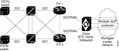
The Cisco BTS 10200 Softswitch communicates with Signaling System 7 (SS7)-based PSTN switches and service control points (SCPs) by using a SIGTRAN-based signaling gateway (SG). The SIGTRAN interface carries all SS7 messages encapsulated in IP packets. The Cisco IP Transfer Point (ITP) is one of the SGs used with the Cisco BTS 10200 Softswitch for this purpose.
Interface to the SS7 Network
The basic interface of the Cisco BTS 10200 Softswitch to the SS7 network is shown in Figure 2-1.
Figure 2-1 Cisco BTS 10200 Softswitch Interface to the SS7 Network
Note
The Cisco BTS 10200 Softswitch can be configured to have multiple originating point codes (OPCs). For information on OPCs, network configuration options, and subsystems, see the Cisco BTS 10200 Softswitch SS7 SIGTRAN Solution Guide.
For additional information, see the following standards and industry documents:
•
•
•
•
•
•
•
Support for ISUP Variants
The Cisco BTS 10200 Softswitch supports the following ISUP variants:
•
•
•
•
•
•
•
•
•
•
•
•
•
ISUP Transparency with the Cisco PGW 2200
ISUP transparency provides the capability for the Cisco BTS 10200 Softswitch to transfer Generic Transparency Descriptor (GTD) messages and information elements across an IP network to a Cisco PGW 2200. In the Cisco PGW 2200, the GTD messages are mapped to ISUP messages, repackaged, and sent out to the PSTN/SS7 network. ISUP transparency is important because it enables the transport of calls from a Session Initiation Protocol (SIP) network through an IP network and out to a PSTN network without any loss of signaling information. ISUP transparency is achieved with the use of the Cisco GTD mechanism. GTD provides a means to specify messages of various protocols used in the PSTN network in plain text format. In that format, they can be easily understood by the network elements (NEs) within the IP network or on the boundary between the PSTN and IP networks.
Note
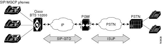
The ISUP transparency function on the BTS-PGW interface, illustrated in Figure 2-2, passes normalized parameters to expedite (1) mapping at the PSTN interconnect side and (2) any feature invocation necessary on either the Cisco PGW 2200 or the Cisco BTS 10200 Softswitch. It adds support for GTD attachments to SIP-T trunk messages, allowing the Cisco BTS 10200 Softswitch to interwork with the Cisco PGW 2200 for interconnection to the PSTN.
Figure 2-2
ISUP Transparency on the BTS-PGW Interface
When the Cisco BTS 10200 Softswitch generates SIP messages to be sent out on SIP-T trunks, a GTD attachment is generated based on the GTD parameters defined in the GTD-PARMS token in the Softswitch Trunk Group Profile (softsw-tg-profile) table. The Cisco PGW 2200 decodes GTD attachments of incoming SIP messages, and converts all GTD parameter contents to the equivalent ISUP values in the appropriate information element on the outgoing PSTN side.
When the egress trunk is a SIP-T trunk, the system supports the mapping of Progress Indication messages from the Cisco BTS 10200 Softswitch to SIP INFO messages with GTD attachments containing Call Progress (CPG) messages. This supported feature applies only to SIP subscribers. When a SIP INFO or RE-INVITE message is received over a SIP-T trunk with a GTD attachment containing a CPG message, a Progress Indication message is generated and sent to the system.
In the deployment model, the Cisco PGW 2200 is the PSTN gateway, and the Cisco BTS 10200 Softswitch provides a residential or Centrex application platform.
PSTN Supplementary Services
The following PSTN supplementary services are enabled by the ISUP transparency feature:
•
–
–
–
•
–
–
–
–
–
•
–
•
–
–
–
–
–
•
–
–
–
–
–
–
–
–
–
–
–
Call Progress Signaling for SIP Subscriber on Call Hold
The Cisco BTS 10200 Softswitch can be provisioned to send a call-hold event signal to the other party in the call when a SIP subscriber goes on or off hold. This provisioning is done by means of the SIP-SUB-SEND-CPG-ON-HOLD-SIGNAL token in the CA-CONFIG table. The default value of this token is N. Therefore, you must change this value to Y if you want this signal to be sent for all SIP subscribers.
Note
Limitations
This feature is subject to the following limitations:
•
•
•
GTD Parameters Supported
Table 2-1 shows the GTD parameters supported by this feature and indicates the GTD messages in which each parameter is supported. The values in the GTD Parameter and Name columns of this table are placed in the static Generic Transparency Descriptor Parameter Values (gtd-parm-values) table. You select values from the GTD Parameter column to provision the GTD-PARMS token in the Softswitch Trunk Group Profile (softsw-tg-profile) table.
Enabling a parameter causes it to be encoded in an outgoing GTD attachment of a SIP message on the trunk group if the information is available in the call context.
Only the GTD parameter listed for each GTD message type is decoded when a SIP message with a GTD attachment is received by the system from the network.
For example, the GTD ACL parameter in a GTD REL message will be decoded if it is received, whether it is provisioned or not. However, a GTD UUS parameter received in a GTD REL message is ignored, even if it is provisioned, because it is not in the table.
Note
Note
Billing Fields
The BTS 10200 and PGW 2200 produce their own independent billing records. Downstream billing mediation servers use the SIP Call ID to correlate the two records, if required. The SIP Call ID is available in the PGW 2200 CDR record, tag 4203, and in the BTS 10200 CDR record, fields 116 and 144.
Cause Code Selection Precedence
The system performs cause code selection according to the following order of precedence:
1.
2.
3.
Troubleshooting
There are no troubleshooting tools created specifically for the transparency feature. Use the existing tools to extract traces from log files on the BTS 10200 and the call trace and siptool capabilities on the PGW 2200. Both tools support ASCII attachments such as the GTD attachment.
Provisioning Procedure
See the "ISUP Transparency on the BTS-PGW Interface" section in the Cisco BTS 10200 Softswitch Provisioning Guide.
Additional SIGTRAN and SS7 Information
For additional information on provisioning and using SIGTRAN and SS7 protocols on the Cisco BTS 10200 Softswitch, see the SIGTRAN Solution Guide.
ISDN Signaling Support
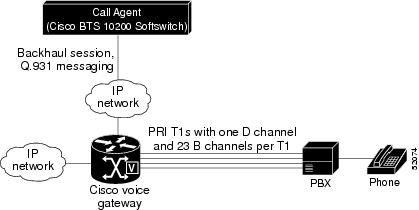
This section describes the Integrated Services Digital Network (ISDN) Primary Rate Interface (PRI) variants and supplementary services supported by the Cisco BTS 10200 Softswitch. ISDN PRI allows the Cisco BTS 10200 Softswitch to interconnect to small and medium businesses using legacy PBX PRI interfaces. The basic ISDN NEs and signaling connections are shown in Figure 2-3.
Note
Figure 2-3 Example of ISDN NEs
The design provides for transport of PRI information elements (IEs) and messages. Interoperability is supported with the following PRI variants:
•
•
•
•
The Cisco BTS 10200 Softswitch supports the following capabilities:
•
•
•
•
•
•
Note
H.323 Signaling Support
Note
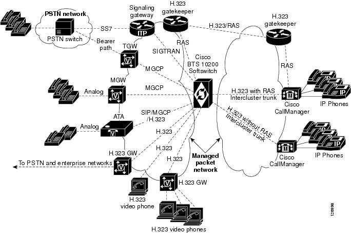
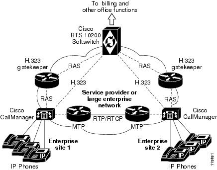
The Cisco BTS 10200 Softswitch functions as a logical H.323 gateway to communicate with H.323 gatekeepers (GKs), and with Cisco CallManager and other H.323 gateways. The Cisco BTS 10200 Softswitch also provides signaling for other trunks and lines over MGCP and SIP protocols. In addition, it communicates with signaling gateways (SGs) for SS7 signaling and with trunking gateways (TGWs) that provide the bearer path to the PSTN. This allows H.323 Internet VoIP traffic to be carried seamlessly into the PSTN networks.
These signaling links are shown in Figure 2-4.
Note
Figure 2-4 Signaling Links between Cisco BTS 10200 Softswitch, Cisco CallManager, and Other Service Provider NEs
The interoperability between the Cisco BTS 10200 Softswitch, Cisco CallManager, and Cisco IOS H.323 gateways enhances the delivery of call control features between enterprise networks and service provider networks. These systems interoperate to provide subscriber features such as call forwarding, call waiting, call transfer, and three-way calling. The Cisco BTS 10200 Softswitch can be used to connect calls between two phones that reside on different Cisco CallManager systems (see Figure 2-5). Signaling of certain information, for example connected name and number information, is transparently passed from the terminating Cisco CallManager to the Cisco BTS 10200 Softswitch and back to the originating Cisco CallManager.
Figure 2-5 Example of Connecting Calls from Phones on Separate Cisco CallManager Systems
Note
SIP and SIP-T Signaling Support
The Cisco BTS 10200 Softswitch uses Session Initiation Protocol (SIP) and SIP for telephones (SIP-T) signaling to communicate with other SIP-based NEs. This implementation is based upon the evolving industry standards for SIP, including IETF document RFC 3261, SIP: Session Initiation Protocol.
Note
SIP Functions
The Cisco BTS 10200 Softswitch supports both SIP trunks and SIP-based subscriber lines (SIP phones). It provides the following SIP-related functions:
•
•
Note
•
•
•
SIP roles performed by the Cisco BTS 10200 Softswitch include:
•
•
•
Applicable SIP references are listed in the "SIP and SIP-T References" section.
SIP Features
The Cisco BTS 10200 Softswitch supports the following SIP features:
•
•
•
•
•
•
–
–
•
•
•
•
•
•
•
•
•
•
•
•
•
SIP-T Support
The Cisco BTS 10200 Softswitch supports SIP-T functions. SIP-T is used to bridge calls between two SS7 networks. SIP-T encapsulates the SS7 ISUP information elements (based on GR-317 ISUP version) and carries them through the packet network. It provides for encapsulation/decapsulation at the PSTN gateways and helps route the call through the packet network. SIP-T functions are described in IETF RFC 3398, Integrated Services Digital Network (ISDN) User Part (ISUP) to Session Initiation Protocol (SIP) Mapping.
FCP Interface
The Cisco BTS 10200 Softswitch uses Feature Control Protocol (FCP) for internal communications between the Call Agent (CA) and Feature Server (FS) components. FCP is a Multipurpose Internet Mail Extension (MIME) application on top of SIP. FCP uses SIP for transport, and carries call state control and status information needed for feature control.
SIP Billing Support
The Cisco BTS 10200 Softswitch provides call data for billing on SIP calls. Specific fields are supported in the call detail records for calls that originate or terminate on a SIP trunk or subscriber line. For detailed information on billing management and data, see the Cisco BTS 10200 Softswitch Billing Interface Guide.
SIP and SIP-T References
The BTS 10200 SIP implementation is based on the evolving standards in the Internet Engineering Task Force (IETF) Request for Comments (RFC) publications, including the documents in the following list, and may not be fully compliant in all cases. The BTS 10200 is largely compliant with RFC 3261. For the level of compliance with all other RFC publications and drafts referenced below, see the specific feature descriptions.
•
•
•
•
•
•
•
•
•
PacketCable-Based Signaling Support
This section summarizes Cisco BTS 10200 Softswitch support for PacketCable-based signaling and includes the following topics:
PacketCable-Based Functions
In a PacketCable-based network, the Cisco BTS 10200 Softswitch functions as both a call management server (CMS) and a media gateway controller (MGC).
The Cisco BTS 10200 Softswitch provides call control, call routing, and signaling for several types of NEs:
•
•
•
The Cisco BTS 10200 Softswitch supports cable access for voice application, including communications with the Cisco UBR 7246 and Cisco UBR 924 universal broadband routers. It also provides interfaces to Record Keeping Servers (RKSs) for billing purposes, and IP security functions.
The Cisco BTS 10200 Softswitch provides support for the following PacketCable-based protocols and functions:
•
•
Note
•
•
•
•
Note
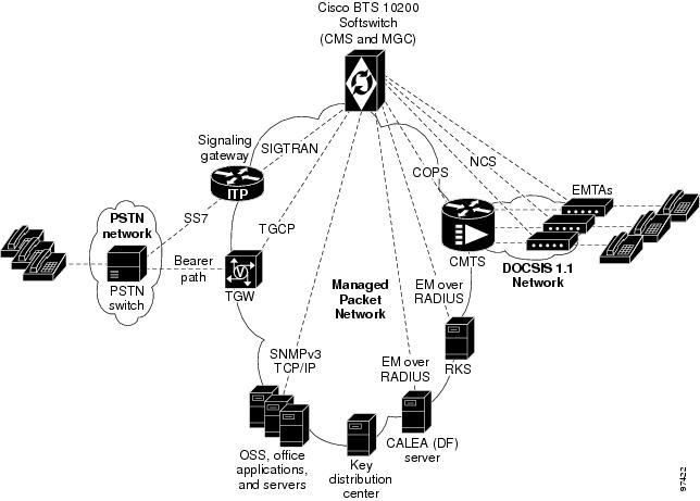
Figure 2-6 shows a typical network with PacketCable-based NEs and the applicable external interfaces of the Cisco BTS 10200 Softswitch.
Figure 2-6 Example of PacketCable-Based Network Architecture
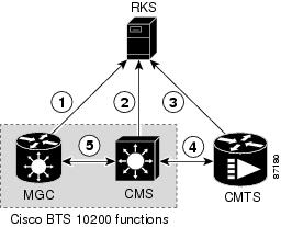
Event Message Implementation
This section describes the implementation of the event message (EM) feature on the Cisco BTS 10200 Softswitch. EMs are real-time call data records containing information about network usage and activities. They are typically used for billing purposes in a PacketCable-based network. The Cisco BTS 10200 Softswitch (which performs the CMS and MGC functions) transfers EMs to an external RKS that assembles call detail records (CDRs) from the EMs.
Note
Figure 2-7 illustrates the PacketCable NEs and interfaces involved in the generation and processing of EMs.
Figure 2-7 Event Message Interfaces
Notes for Figure 2-71.
2.
3.
4.
5.
Note
Security Implementation
The implementation of PKT-SP-SEC-I07-021127, PacketCable Security Specification, November 27, 2002, provides a security scheme for the voice-over-cable network based on a set of security protocols. These protocols, described in the documents listed below, provide authentication (to help prevent theft of bandwidth, denial-of-service attack, replay, and so forth) and enable message integrity, privacy, and confidentiality.
•
–
–
•
–
–
The Cisco BTS 10200 Softswitch performs the security functions of the CMS and MGC in the PacketCable environment. It supports security in accordance with PKT-SP-SEC-I07-021127 for both signaling and media:
•
•
A special parameter, IPSEC_ENABLED, must be set in the opticall configuration file (opticall.cfg) at the time of software installation to enable the IPsec feature. The IPSEC_ENABLED value cannot be changed by use of CLI commands.
Note