Table Of Contents
Cisco BTS 10200 Softswitch Technical Overview
Introduction
Cisco BTS 10200 Softswitch in the TMN Model
Overview of Features and Functions
Network Features and Functions
Subscriber Features
Billing Features and Functions
Operations, Maintenance, and Troubleshooting Features and Functions
System Administration Features and Functions
Logical Components
List of Logical Components
CA Functions
Signaling Adapters
Billing Data Generation and Interfaces
FS Functions
EMS Functions
EMS Communications
SNMP Agent
BDMS Functions
MBA Functions
Reliability and Availability of Components
Dual Active/Standby Configuration
Process Restartability
Cisco Specified Hardware
General Description and Important Notices
Regulatory Compliance
Site Preparation
Cisco BTS 10200 Softswitch Technical Overview
Revised: March 19, 2007, OL-5906-14
This chapter provides a summary of the features and functions of the Cisco BTS 10200 Softswitch. The following topics are discussed in this chapter:
•
Introduction
•
Cisco BTS 10200 Softswitch in the TMN Model
•
Overview of Features and Functions
•
Logical Components
•
Cisco Specified Hardware
•
Site Preparation
Note
All of the features and functions described in this document are applicable to both Release 4.4.0 and Release 4.4.1, unless specifically noted. Release 4.4.x refers to both Release 4.4.0 and 4.4.1.
Introduction
The Cisco BTS 10200 Softswitch is a software-based, class-independent network switch. It provides call-control intelligence for establishing, maintaining, routing, and terminating voice calls through the packet network via media gateways (MGWs), while seamlessly operating with legacy circuit-switched networks. In VoIP networks it processes incoming and outgoing calls between the packet network and the public switched telephone network (PSTN). The Cisco BTS 10200 Softswitch provides the major signaling functions performed by traditional Class 4 and Class 5 switching systems in the PSTN. It also provides more than 40 provisionable subscriber features, and management interfaces for provisioning, monitoring, control, and billing operations.
Note
The bearer path infrastructure is provided via MGWs, which interface circuit-switched facilities with packet networks. The MGWs provide encoding/decoding and packetization/ depacketization functions.
When Cisco BTS 10200 Softswitch application software is installed on Cisco specified host machines, it creates a set of logical components. Together these logical components provide all of the features and functions of the Cisco BTS 10200 Softswitch. The disk drives in the host machines store the provisioned database and system-generated data. These logical components, and the Cisco specified hardware, are described later in this chapter.
The Cisco BTS 10200 Softswitch communicates with a wide range of network elements (NEs) including
•
Service provider network management and support systems
•
Gateways to managed packet networks and PSTN
•
NEs that support network and subscriber services such as billing mediation and record keeping, interactive voice response (IVR), announcements, law enforcement and emergency services, operator services, and so forth.
When ordering the Cisco BTS 10200 Softswitch software, your Cisco account team will work with you to determine appropriate hardware options, software loads, and license level options for each of your sites.
Note
License level options involve the number of subscribers/DS0 lines and calls per second (CPS). You can order increased subscriber/DS0 and CPS license levels from your Cisco account team.
Cisco BTS 10200 Softswitch in the TMN Model
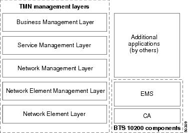
Figure 1-1 illustrates the role of the Cisco BTS 10200 Softswitch in the Telecommunications Management Network (TMN) model. The Cisco BTS 10200 Softswitch is involved in the Network Element Layer and Network Element Management Layer.
Figure 1-1 Cisco BTS 10200 Softswitch Components in the TMN Model
Note
The Call Agent (CA) and Element Management System (EMS) components of the Cisco BTS 10200 Softswitch, as shown in Figure 1-1, are described in the "Logical Components" section.
The role of each TMN layer is described below.
The Business Management Layer contains the following elements:
•
Network planning
•
Intercarrier agreements
•
Strategic planning
•
Enterprise-level management
The Service Management Layer contains the following elements:
•
Customer interface
•
Service provisioning
•
Account management
•
Customer-complaint management
•
Integrated faults, billing, and quality of service (QoS)
The Network Management Layer contains the following elements:
•
End-to-end network view
•
All data aggregated to the network view
•
Physical entity awareness
The Network Element Management Layer contains the following elements:
•
Subnet management
•
Element management
•
Reduced workload on the Network Management Layer
•
Common NEs aggregated in a network
The Network Element Layer contains the following elements:
•
Performance data generation
•
Self-diagnostics
•
Alarm monitoring and generation
•
Protocol conversions
•
Billing generation
Overview of Features and Functions
The Cisco BTS 10200 Softswitch provides a large number of features and functions. This section contains quick-reference lists of the features and functions in the following categories:
•
Network Features and Functions
•
Subscriber Features
•
Billing Features and Functions
•
Operations, Maintenance, and Troubleshooting Features and Functions
•
System Administration Features and Functions
Tip
This list is intended as a general overview. Additional features and functions are described within the complete documentation set for this product.
Network Features and Functions
The system supports the following network features and functions:
•
Call control intelligence for establishing, maintaining, routing, and terminating voice calls through the packet network via media gateways (MGWs), while seamlessly operating with circuit-switched networks.
•
Support for a number of network signaling protocols, including MGCP, SIGTRAN (for SS7), H.323, PacketCable, Session Initiation Protocol (SIP), ISDN, and channel-associated signaling (CAS).
•
PSTN-parity routing mechanisms for voice calls including local, national, international, operator services, and emergency services routing. (In North America, this includes local access and transport area (LATA) calls and interLATA calls.)
•
Support for the following types of calls:
–
PSTN-to-Packet Network calls—Calls that originate on a PSTN network and terminate on a packet network (off-net calls).
–
Packet-to-PSTN Network calls—Calls that originate on a packet network and terminate on a PSTN network (off-net calls).
–
Packet-to-Packet calls—Calls that originate and terminate on a packet network (packet on-net calls).
–
PSTN-to-Packet-to-PSTN calls—Calls that originate on an ingress PSTN circuit and travel over a packet network to terminate on an egress PSTN port.
•
Support for the following types of routing, configurable via command-line provisioning:
–
Trunk-based routing, with trunk group (TG) selection options as follows: least-cost routing, round robin, or sequential order.
–
Policy routing, including origin-dependent routing, originating line information (OLI) routing, percent routing, point of presence (POP) routing, prefix-based routing, region-based routing, time-of-day routing, and NXX-based routing.
–
Equal access routing.
•
Support for route advance—The route table in the Cisco BTS 10200 Softswitch database allows the service provider to provision a list of up to 10 trunk groups (TG1 to TG10), and a parameter for selecting the priority of the TGs for routing (TG-SELECTION). The system attempts to route the call on the highest priority TG. If the call cannot be completed on the highest priority TG, the system attempts to use the next (lower priority) TG, a process known as route advance. The system attempts route advance to lower priority TGs up to five times. (Any TG in the list that is administratively out of service is not counted as an attempt.) If all five attempts fail, the call is released, and the system provides a release announcement.
•
Digit manipulation function, which enables the Cisco BTS 10200 Softswitch to modify the calling party dial number, called party number, and nature of address (NOA) for both incoming and outgoing calls. This feature supports the use of:
–
North American Numbering Plan (NANP).
–
ITU-T E.164 numbering plan.
–
ANI- or DNIS-based routing.
Note
The calling party number is also known as ANI (automatic number identification), and the called party number is also known as DNIS (dialed number identification service).
NOA values include international number, national number, operator call, subscriber number, test line, unknown, and up to six network-specific designations.
•
Support for domestic and international equal-access direct dialing based on presubscribed interexchange carrier (PIC).
•
Support for provisionable Common Language Location Identifier (CLLI) codes:
–
Provides identification of the local switch (Cisco BTS 10200 Softswitch) and the remote switch (the switch at the far end of the applicable trunk group).
–
Supports sending and receiving CLLI code in circuit validation response (CVR) messages—CVR messages are generated in response to a circuit validation test (CVT) message.
•
Control of announcement servers.
•
Communications with interactive voice response (IVR) servers.
•
SIGTRAN-based communications with signaling gateways (SGs) that provide SS7 signaling and interoperability with legacy PSTN equipment.
•
Interoperability with PBX equipment via ISDN-PRI and channel-associated signaling (CAS) protocols.
•
Generation of triggers allows service providers to offer enhanced services using external service platforms (consistent with the ITU CS-2 call model).
•
Enhanced Centrex services (virtual office) for business subscribers, including telecommuters and mobile workers.
•
Dial offload—Dial offload involves intercepting Internet traffic at inbound Class 5 locations and carrying this traffic over the packet network (instead of the PSTN) to the Internet service providers (ISPs).
•
Call control functions for the H.323-based gateways and endpoints.
•
Support for H.323 Annex E User Datagram Protocol (UDP) functionality, which preserves stable calls during a process restart or component switchover on the CA.
•
Interworking with Cisco CallManager using H.323 protocol.
•
Call control functions for Tandem applications.
•
Call control functions for SIP-enabled networks.
•
Call control functions for PacketCable-based networks, including support for Common Open Policy Service (COPS), Network-Based Call Signaling (NCS) protocol, and Trunking Gateway Control Protocol (TGCP) signaling, as well as IPsec and dynamic quality of service (DQoS) features.
•
T.38 fax relay.
•
Public safety answering point (PSAP) support for Enhanced 911 Emergency Services.
•
Interfaces for support of the Communications Assistance for Law Enforcement Act (CALEA), in both PacketCable and Cisco Service Independent Intercept (SII) architectures.
•
Support for the automatic call gap (ACG) function with service control point (SCP) query.
Subscriber Features
The system supports the following subscriber features:
•
Call processing, subscriber services and features, billing support and carrier class availability/reliability for subscribers and trunks connected to media gateways.
•
A large number of voice-handling features, such as call waiting, call holding, call transferring, multiline hunting and caller identification (see the other chapters in this document for complete coverage).
•
Class of service (CoS) screening and outbound call barring (OCB).
Billing Features and Functions
The system supports the following billing features and functions:
•
Provisionable option for FTP or SFTP transfer of call data to a remote billing server or third-party billing mediation device.
•
User-provisionable billing collection and transfer parameters.
•
User-configurable billing reporting by call type.
•
Option for call detail block (CDB) or event message (EM) billing data formats.
Note
See the Cisco BTS 10200 Softswitch Billing Interface Guide for a complete description of the billing functions.
Operations, Maintenance, and Troubleshooting Features and Functions
The system supports the following operations, maintenance, and troubleshooting features and functions:
•
Hardware sizing options appropriate for a variety of traffic types and call rates.
•
Redundant hardware and software fail-safes to provide reliable operation and minimize the chance of an outage.
•
Support for regular database backup, and recovery of data from backup files.
Note
Data should be backed up on a daily basis and saved to a remote server. Data backup files are needed in the unlikely event that data in both the primary and secondary sides of any platform become corrupted. In that case, the data must be restored from a backup file.
•
Periodic and scheduled audits of circuits to detect and clear "hung" circuits. Audits are performed on:
–
SS7 circuits
–
MGCP trunking gateway circuits
•
Command-line based dialed-number query tools:
–
A query verification tool (QVT)—This tool generates Transaction Capabilities Applications Part (TCAP) queries to the SCP database, and reports query results.
–
A translation verification tool (TVT)—This tool determines the routing for a call by traversing through the tables provisioned in the database without originating any call.
•
Traffic measurements, such as call-completion counters, resource status and congestion information.
•
Event and alarm reports, including user provisioning of report filters.
•
Congestion detection and protection feature, with the following characteristics:
–
Detects internal messaging congestion caused by traffic overload or other extraordinary events, and takes preventive action to avoid system failure.
–
When the Cisco BTS 10200 Softswitch is in a congested state, emergency messages are given special treatment and are allowed to pass through.
•
Provisionable option to suppress sending of Internet Control Message Protocol (ICMP) ping—The service provider can enable or disable sending ICMP pings to MGWs. (The Cisco BTS 10200 Softswitch sends an ICMP ping only when an audit-endpoint [AUEP] attempt fails.)
System Administration Features and Functions
The system supports the following system administration features and functions:
•
Secure communications using SSH, SFTP, Secure XML, and HTTPS interfaces.
•
Hardened Solaris OS—The Cisco BTS 10200 Softswitch runs on Sun Solaris. Processes and utilities in the UNIX system that are unsuitable for use in a softswitch environment have been disabled.
•
Login authentication—The Cisco BTS 10200 Softswitch supports administrative login authentication using Lightweight Directory Access Protocol (LDAP) and RADIUS authentication clients. This functionality is applicable to the Cisco Extensible Provisioning and Operations Manager (EPOM) and Cisco Self-Service Phone Administration (SPA). The system can determine if the account is local or off-board, and transfer login responsibility for off-board accounts to the end-user authentication, authorization, and accounting (AAA) servers. This capability is provisionable via command-line interface (CLI) commands.
•
Common Object Request Broker Architecture (CORBA) Adapter (CAD) interface—The CAD provides an abstraction of the Cisco BTS 10200 Softswitch in a consistent, object-oriented model. The CAD interface supports a means of provisioning the Cisco BTS 10200 Softswitch that parallels the CLI adapter capabilities. The system provides a secure socket layer (SSL) transport for the CORBA adapter.
Note
For CORBA details, see the Cisco BTS 10200 Softswitch CORBA Adapter Interface Specification Programmer Guide.
•
A provisionable database containing data for basic call processing, billing, and special call features.
•
Communication with the existing Operations Support System (OSS) infrastructure—including network management systems (NMSs)—to support fault, configuration, accounting, performance, and security (FCAPS) functions.
•
Communication with the Cisco SPA—Cisco SPA uses a web-based interface for feature self-provisioning and account management that can be used by consumers, account holders, and service providers. It enables the end user to manipulate existing features and query account information without service provider intervention or labor.
Note
The SPA function requires additional hardware—It does not run on the Cisco BTS 10200 Softswitch hardware platform.
Logical Components
This section discusses the logical components of the Cisco BTS 10200 Softswitch and describes the functions of each component. The information is organized as follows:
•
List of Logical Components
•
CA Functions
•
FS Functions
•
EMS Functions
•
BDMS Functions
•
MBA Functions
•
Reliability and Availability of Components
List of Logical Components
The Cisco BTS 10200 Softswitch consists of five independent logical components in a distributed architecture:
•
Call Agent (CA)—Serves as a call management system and media gateway controller. It handles the establishment, processing, and teardown of telephony calls.
•
Feature Servers (FSs)—Provide POTS, Tandem, Centrex, and Advanced Intelligent Network (AIN) services to the calls controlled by the CAs. The FSs also provide processing for service features such as call forwarding, call waiting, local number portability, and so forth.
There are two types of FSs in the Cisco BTS 10200 Softswitch:
–
FSPTC—FS for POTS, Tandem, and Centrex features
–
FSAIN—FS for AIN services
•
Element Management System (EMS)—Controls the entire Cisco BTS 10200 Softswitch, and acts as a mediation device between a network management system (NMS) and one or more CAs. It is also the interface for the provisioning, administration, and reporting features of the Cisco BTS 10200 Softswitch.
•
Bulk Data Management System (BDMS)—Coordinates the collection of billing data from the CA, and the forwarding of billing records to the service provider billing mediation device.
•
Mini-Browser Adapter (MBA)—Performs GUI management for GUI-enabled SIP phone handsets. This GUI allows SIP phone users to self-provision certain features. The MBA runs on a separate Sun host machine that is not part of the standard Cisco BTS 10200 Softswitch hardware set.
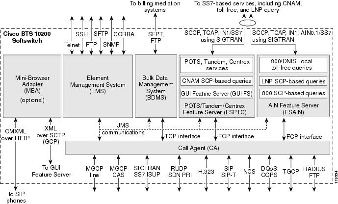
The architecture and interworking of the logical components (CA, FS, EMS, BDMS, and MBA) are shown in Figure 1-2. The detailed functions of each component are described in the sections that follow.
Figure 1-2 Cisco BTS 10200 Softswitch Architecture, Showing Logical Components
The MBA runs on a separate Sun host machine that is not part of the standard Cisco BTS 10200 Softswitch hardware set.
The minimal/earliest CMXML version supported for communications between the MBA and SIP phones is CMXML 3.0.
CA Functions
The Call Agent (CA) provides monitoring and control of external NEs. It connects to multiple networks via the signaling adapter interface. This interface converts incoming and outgoing signaling to and from the standard internal format of the CA. This interface allows the CA to connect to multiple networks and exchange signaling messages for setup, teardown, and transfer of calls.
Signaling Adapters
The signaling adapters perform the following functions:
•
Provide uniform primitives (signaling indications) for all interactions between different protocol stacks and the CA modules.
•
Provide uniform data structures containing common information elements from different signaling protocols.
•
Provide call control primitives for exchanging all call signaling messages between CA and the signaling network.
•
Provide maintenance primitives for signaling link hardware maintenance and signaling protocol stack provisioning.
Billing Data Generation and Interfaces
The CA supports the following billing data generation methods:
•
Call detail blocks (CDBs)—This is traditional post-call billing data, which the CA sends via internal communications to the BDMS (see Figure 1-3). The BDMS forwards this data via FTP or SFTP (a provisionable option) to a third-party billing mediation device. For additional information on the BDMS, see the "BDMS Functions" section.
•
PacketCable event messages (EMs)—This is real-time call data flow, which is transferred directly from the CA to an external Record Keeping Server (RKS) that assembles call detail records (CDRs) from the EMs. The following billing interfaces are provided for EMs on the CA (see Figure 1-3):
–
Remote authentication dial-in user service (RADIUS)—Used by the CA to transmit EMs automatically to an external RKS
–
FTP—Used for manual transfer of EMs from the CA to the RKS
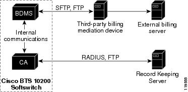
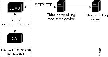
Figure 1-3 CA Billing Interfaces
Caution 
Cisco strongly recommends that you do not provision the system to generate CDBs and EMs simultaneously. Attempting to generate both types of records simultaneously can significantly degrade system performance.
Note
FTP sessions are used for file transfers initiated by the Cisco BTS 10200 Softswitch.
FS Functions
There are two different types of Feature Servers (FSs) in the Cisco BTS 10200 Softswitch.
•
FSPTC—FS for POTS, Tandem, and Centrex features
•
FSAIN—FS for Advanced Intelligent Network services
Each FS communicates internally with the CA, and externally (via a signaling gateway) with STPs that are part of the SS7 signaling system.
The FSs provide access to features through a well-defined interface. The Cisco BTS 10200 Softswitch architecture logically separates the FSs (which provide feature control) from the CA (which provides call control) with a clear interface—Feature Control Protocol (FCP)—defined between them. The FSs provide support for POTS, Centrex, AIN, 8XX service, and other enhanced services. The FSs are colocated on the same machine as the CA.
An FS is invoked from a call detection point (DP) in the CA. For each DP, the CA checks if any triggers are armed. If a trigger is armed, the CA checks if the trigger applies to the subscriber, group, or office (in that order). If the trigger is applicable, the CA invokes the FS associated with that trigger. The Cisco BTS 10200 Softswitch call processing mechanisms are based on the ITU CS-2 call model. For DP details, see the Cisco BTS 10200 Softswitch Operations Manual.
The FSAIN supports the automatic call gap (ACG) function for communications with a service control point (SCP). When an SCP sends a message to the FSAIN regarding the allowed query rate, the Cisco BTS 10200 Softswitch adjusts its query rate accordingly.
EMS Functions
The Element Management System (EMS) manages all of the Cisco BTS 10200 Softswitch components and provides operations, administration, maintenance, and provisioning (OAM&P) interfaces for monitoring and control. It provides the following user OAM&P capabilities:
•
Access the system via a secure interface.
•
Perform system administration and security functions.
•
Show, add, change, or delete the database information through a local or remote interface.
•
Display reports of events, alarms, and faults.
•
Monitor and manage hardware.
•
Monitor and manage traffic measurements.
•
Monitor and manage queuing and audit functions.
•
Display and control the status of a component.
The internal database contains the provisioned data for basic call processing, billing, and special call features. Key data structures are stored in shared memory and are accessible to any process in the system. A library of read/write locks controls access to shared memory. The data structures are implemented using Oracle in the EMS/BDMS, and an indexed database (IDX) in the CA/FS.
Note
For additional information on using these functions, see the Cisco BTS 10200 Softswitch Operations, Maintenance, and Troubleshooting Guide, the Cisco BTS 10200 Softswitch Provisioning Guide, and the Cisco BTS 10200 Softswitch Command Line Interface Reference Guide.
The EMS provides a flexible mechanism to transport information over any protocol to any external device. The EMS interface design takes into account that each carrier has its own unique set of Operations Support Systems (OSSs). The EMS provides a decoupling layer between the external protocols used within the service provider network and the internal protocols of the Cisco BTS 10200 Softswitch. The core system does not need to interpret the specific data formats used by the other carrier network elements.
EMS Communications
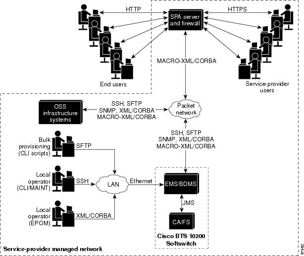
Operators, network administrators, and end users can communicate with the EMS from their workstations or PCs over the interfaces shown in Figure 1-4.
Figure 1-4 Preferred EMS Management Interfaces for Service Provider and End Users
The user interfaces include the following:
•
Secure shell (SSH)—For provisioning via CLI and Maintenance (MAINT) shells.
–
CLI shell—Used for entering entire commands and their parameters from the command line.
–
MAINT shell—Provides a maintenance interface for CLI commands that does not time out or disconnect on switchover. It supplies a prompt based on the username.
Note
After software installation, you must enable CLI provisioning by applying database licenses. You will not be able to run CLI commands until this is done. Your Cisco account team can provide the necessary licenses and procedures.
•
Secure File Transfer Protocol (SFTP)—For bulk provisioning sessions. SSH and SFTP are always available on the Cisco BTS 10200 Softswitch, and there is no command to turn them off.
Note
For security purposes, Telnet is no longer supported as of Release 4.4.x.
•
XML/CORBA and MACRO-XML/CORBA support the following:
–
CORBA provisioning and monitoring interface
–
Provisioning via the Cisco Extensible Provisioning and Operations Manager (EPOM) and the Cisco Self-Service Phone Administration (SPA)
Note
MACRO-XML/CORBA is a read-only interface that end users can configure and use to display large sets of data. It is used to streamline data queries and display complex data relationships.
–
CORBA over SSL for communications with the Cisco BTS 10200 Softswitch
•
Simple Network Management Protocol (SNMP)—Provides traps, status, control, and measurement functions, and provisionable community strings
•
Hypertext Transfer Protocol (HTTP) and Secure Hypertext Transfer Protocol (HTTPS)—Permits end users and service providers to perform many of the feature provisioning processes via the web-based Cisco SPA system. Access from the user's web browser to the SPA server is via HTTP. Access from the service provider's web browser is via HTTPS.
By default, SFTP sessions are used for file transfers initiated by elements outside the Cisco BTS 10200 Softswitch (and directed toward the Cisco BTS 10200 Softswitch). FTP sessions are used for file transfers initiated by the Cisco BTS 10200 Softswitch.
Note
The functions of the BDMS component, including billing-related communications links, are described in the "BDMS Functions" section.
SNMP Agent
The following functions are supported by the Cisco BTS 10200 Softswitch SNMP Agent:
•
Collection of statistics and traffic management data
•
Status and control
•
SNMP trap reports
•
Bulk Status and control
The SNMP agent supports SNMPv2c operations defined by the opticall.mib Management Information Base (MIB). The MIB is located in the directory /opt/BTSsnmp/etc on the EMS. The NMS needs to load the main MIB (opticall.mib), that will in turn import three other MIBs— IPCELL-TC, SNMPv2-TC, and SNMPv2-SMI. The main MIB uses variables from these other three MIBs.
BDMS Functions
The Bulk Data Management System (BDMS) stores billing data in the form of call detail blocks (CDBs). CDBs are assembled from billing messages generated in the CA when billing-related call events occur during call processing. The BDMS formats the CDBs into a flat ASCII-file format, and transmits them to an external billing collection and mediation device that is part of the service provider billing system (see Figure 1-5). Finally, the BDMS forwards this data to an external billing mediation system or billing server, where it is assembled into CDRs.
Note
The interface to the billing mediation device can vary from carrier to carrier. The BDMS supports a flexible profiling system that allows the Cisco BTS 10200 Softswitch to adapt to changes in the billing mediation device interface. The BDMS transmits billing records via FTP or SFTP to the mediation device at regular time intervals that are provisionable in the Cisco BTS 10200 Softswitch.
The BDMS provides the following billing functions:
•
Supports batch record transmission via FTP and SFTP.
•
Issues events as appropriate including potential billing data overwrites.
•
Saves billing data records in persistent store—The allocated storage space is provisionable using CLI commands and can range from 10 MB to 5 GB (default 1 GB).
•
Supports user-provisionable billing subsystem parameters.
•
Supports on-demand CDB queries based on file name, time interval, call type, service type, termination cause, terminating number, originating number, or last record(s) written.
See the Cisco BTS 10200 Softswitch Billing Interface Guide for CDB billing procedures and for detailed descriptions of basic call billing data and feature billing data.
Note
FTP sessions are used for file transfers initiated by the Cisco BTS 10200 Softswitch.
Figure 1-5 Billing Interface to the BDMS
MBA Functions
SIP phones interface via the IP network with the Mini-Browser Adapter (MBA) for services. The user accesses service functions via the "services" key on the SIP phone. A GUI on the SIP phone allows users to self-provision certain features. The MBA supports these services and performs GUI management for the GUI-enabled SIP-phone handsets.
Figure 1-2 shows the MBA and its interfaces:
•
The MBA interfaces with the GUI feature server (GFS) in the FSPTC. The GFS is the feature server data access component for GUI management, and is responsible for subscriber data access and northbound updates into the EMS. Internal signaling between the MBA and the GFS is via GUI Control Protocol (GCP), which is an XML-based protocol over SCTP links.
•
Signaling between the MBA and SIP phones uses Cisco CMXML protocol over HTTP.
Reliability and Availability of Components
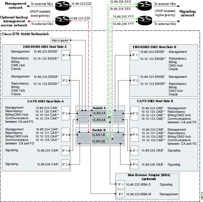
The Cisco BTS 10200 Softswitch network configuration is shown in Figure 1-6. This configuration provides redundant host machines for the EMS/BDMS and CA/FS components, redundant management local area networks (LANs), and six interfaces to the external routers. The configuration enhances security by separating management traffic from signaling traffic. As shown in the drawing, the service provider has the option of installing a backup management access network.
Note
The MBA runs on a separate host machine and uses single (nonredundant) links for management and signaling.
Figure 1-6 Cisco BTS 10200 Softswitch Network Configuration
1.
The following labels represent specific components and functions:
–
IF = Interface.
–
A* and B* represent physical IP addresses; A** and B** represent logical IP addresses.
–
Signaling: MGCP, SIP, and H.323 signaling functions use logical IP addresses that are migrated to the other signaling interface when the platform switches over.
–
OMS Hub carries internal communications.
2.
The IP addresses shown in the figure are for illustration purposes only. IP address examples beginning with 10.89 indicate externally viewable addresses, and those beginning with 10.10 indicate internal nonroutable addresses. The actual IP address data for each Cisco BTS 10200 Softswitch is in the Network Information Data Sheet that was supplied with your specific system.
3.
ICMP Router Discovery Protocol (IRDP) advertisement must be enabled on the routers. IRDP on the management network routers must be set to a lower priority than the IRDP level on the signaling network.
4.
"To external NEs" refers to the following links in the service provider network:
•
Uplinks for external access to hosts, used for management services (via SSH, SFTP, and so forth), DNS services, and outbound billing data (via FTP or SFTP).
•
Uplinks for external communications, used for connection to external NEs via an IRDP-enabled network.
5.
The following restrictions apply for administrative access to the Cisco BTS 10200 Softswitch via the management network:
•
To access the management network of the Cisco BTS 10200 Softswitch from an external host, the external host must be in the same network as the management network.
•
If the external host is in a different network, the operator can set up a static route to each of the CA hosts, and this will allow the external host to access the management network.
6.
To support full system redundancy, you must connect the external uplinks from the Catalyst switches to separate routers as shown in Figure 1-6:
–
There must be dual (redundant) signaling uplinks from each Catalyst switch, so that each Catalyst switch is connected to each signaling router.
–
There must be a single management uplink from Catalyst Switch A to one of the management routers. A second management uplink, from Catalyst B to the other management router, is optional.
–
The routers must be connected to separate networks with diverse routing paths to the applicable external NEs and services (such as OSS, DNS, media gateways, and announcement servers).
Caution 
If each external signaling uplink is not connected as described in Note #
6., a single point of failure could cause a traffic interruption.
7.
It is important to ensure redundancy of the DNS lookup function, so that this function is not completely lost in the event of a network outage. Cisco recommends that two (redundant) DNS units be deployed in the service provider network, and that the two DNS units be reachable via separate networks with diverse routing paths. Cisco recommends that you place the DNSs behind a load balancer so that a single IP address is exported to clients such as the Cisco BTS 10200 Softswitch.
Caution 
If both DNS servers become unreachable, a traffic interruption may occur.
8.
The alarm panel refers to a terminal server (which could be a terminal server built into an alarm panel). It could be customer supplied or Cisco supplied, depending on the hardware options selected. The alarm panel supplied with some Cisco BTS 10200 Softswitch systems is not used for alarms or for aggregation or reporting of machine alarms, but rather is used as a form of terminal concentrator. The Cisco BTS 10200 Softswitch software does not transmit machine alarms through this port. Instead, machine alarms are sent via alarm reports, as described in the Cisco BTS 10200 Softswitch Operations, Maintenance, and Troubleshooting Guide.
Dual Active/Standby Configuration
Note
This section is applicable to the EMS, BDMS, CA, and FS components, but not the MBA component. The MBA is not deployed in a dual configuration.
Each logical component (EMS, BDMS, CA, and FS) is deployed in a dual active/standby configuration, with the two sides running on separate computers (hosts). The active side of each component is backed up by a standby side on the other host. The communication paths among the components are also redundant. The redundant architecture supports the reliability and availability of the entire system. The active and standby sides of each logical component pair operate as follows:
•
There is no traffic load sharing between the active and standby sides; the active side performs all of the call processing, and the standby does none.
•
Call and feature data from the active side are replicated to the standby side at specific checkpoints of a call (when a call is answered, released, and so forth).
•
An automatic internal audit function runs on the standby side of each component—EMS, BDMS, CA, and FS. It checks all the shared memory tables in the components to verify consistency and to check for any corruption. The audit reports any data structure inconsistencies or corruption via alarms and trace messages.
•
Each side maintains a keepalive channel with the corresponding mate side. The keepalive process on each side determines if the mate is faulty. If there is a failure on the active side (or if the operator intentionally brings down the active side), the other side becomes active and takes over the traffic load. All stable calls continue to be processed without any loss of calls. There is no service outage, but during a switchover, transient calls can be impacted.
Note
H.323 call stability relies on H.323 Annex E functionality at both H.323 endpoints.
When the side that failed is brought back in service, it remains in standby mode and the system runs in normal duplex mode.
•
IP Manager, a built-in IP management function, provides logical interfaces to several signaling-protocol components (such as MGCP, H.323, SIP) for remote devices on the currently active CA/FS. If IP Manager detects a CA/FS platform failover (from primary to secondary or vice-versa), it migrates the IP addresses of the logical interfaces over to the newly active CA/FS side.
Note
IP Manager only migrates IP addresses on the same subnet. In the case of a multi-homed platform, when one of the interfaces fails, IP Manager does not migrate the IP address to a different interface.
•
The operator can manually switch (force) either side to become active, which automatically forces the other side into standby mode.
Process Restartability
When a Cisco BTS 10200 Softswitch process exits due to an internal error (such as SIGSEGV on UNIX) or is terminated by the platform, the system automatically restarts the process that shut down. Restarting the process is a preferred alternative to switching over to the mate, because the restart preserves stable calls and also attempts to preserve transient calls. When a process is restarted, the process audits information such as resource states and attempts to repair inconsistencies. If a process experiences a high failure rate (even after repeated restarts), the system will switch over to the mate.
Cisco Specified Hardware
Note
The MBA runs on a separate Sun host machine that is not part of the standard Cisco specified hardware set. Contact your Cisco account representative if you need additional information about the MBA component.
The Cisco BTS 10200 Softswitch software must be loaded on the appropriate Cisco specified hardware. These hardware options are listed in the Cisco BTS 10200 Softswitch Release Notes.
General Description and Important Notices
Each newly installed system requires the following devices:
•
Four UNIX-based host machines running the Solaris operating system (see the Cisco BTS 10200 Softswitch Release Notes for applicable updates regarding Solaris patch levels)
•
Two Cisco Catalyst 2950M XL Fast Ethernet Switches
•
Terminal server (or alarm panel that includes a terminal server)
•
DC power distribution unit (PDU) or two AC power strips, as applicable
Two host machines are used for the EMS/BDMS components and two host machines are used for the CA/FS components. The use of duplex host machines supports the redundancy operations of the logical components.
Equipment must be mounted in racks or cabinets that meet local service provider site requirements. Rack configurations can vary according to service providers requirements and preferences.
Note
Consult your Cisco account team to determine which platform option best fits your current and future network requirements and traffic levels. Your Cisco account team can also provide you with options for purchasing hardware directly from Cisco or via reference sale.
Note
Cisco TAC does not support hardware when purchased directly from Sun or another vendor. Hardware support contracts should be purchased from Sun, or a Sun Value Added Reseller.
Caution 
Be sure to use one of the hardware sets specified by Cisco in the in the
Cisco BTS 10200 Softswitch Release Notes. Cisco TAC only supports Cisco BTS 10200 Softswitch systems running on these Cisco specified hardware configurations. The software is not supported on any other types or combinations of hardware.
Note
See the "Site Preparation" section for the site requirements applicable to these hardware sets. These requirements are essential to proper system operation.
Regulatory Compliance
The Cisco BTS 10200 Softswitch complies with the standards listed in Table 1-1.
Table 1-1 Standards Compliance
Specification
|
Industry Standard
|
Information Technology Equipment
|
UL1 1950
|
EMI2
|
FCC3 Class A (47CFR, Part 15)
|
Environmental compatibility
|
NEBS4 Level 1 and Level 3 Requirements (SR-3580)
|
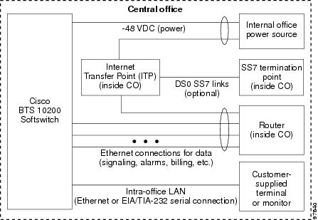
The Code of Federal Regulations Title 47 (CFR 47) Part 68, Connection of terminal equipment to the telephone network, does not apply to this product. All of the points of demarcation are located at the first physical connection external to the Cisco BTS 10200 Softswitch frame, which are at customer-provided equipment internal to the central office (CO). See Figure 1-7 for a block diagram.
Figure 1-7 Cisco BTS 10200 Softswitch Connection to Internal CO Equipment
Site Preparation
This section describes the installation site requirements for the Cisco BTS 10200 Softswitch. Installation procedures are provided separately.
Required Facilities
The Cisco BTS 10200 Softswitch interfaces with a variety of NEs using various protocols. The facilities connecting the Cisco BTS 10200 Softswitch to these NEs are customer supplied.
Intershelf Cables
The procedures for cabling the intershelf cables (those that connect the various host machines and Ethernet Switches within the Cisco BTS 10200 Softswitch) are documented in the Cisco BTS 10200 Softswitch Cabling and IRDP Procedures. If your hardware was purchased as part of a complete integrated and tested system from Cisco Systems, the intershelf cables are included with your order.
Cables for Connection to External NEs
Cables for connections to external NEs are not included with the Cisco BTS 10200 Softswitch order, and are customer supplied.
Operator Access to the Cisco BTS 10200 Softswitch
System administrators and operators can access the Cisco BTS 10200 Softswitch via a number of interfaces, including secure shell (SSH) session to the EMS over Ethernet, and via OSS and NMS connections. Communications can be interactive or via batch mode (batch mode uses SFTP). See the "EMS Functions" section for additional user interface options.
Site Environmental and Power Requirements
The environmental and power requirements for installation of the Cisco BTS 10200 Softswitch are documented in the Cisco BTS 10200 Softswitch Building Environment and Power Site Survey document, available from your Cisco account team.
Caution 
Cisco strongly recommends that you use uninterruptible power for both AC and DC systems. The uninterruptible supply should be engineered to support system operation through any possible power interruption.
Caution 
For DC-powered installations, the power must come from two separate dedicated DC branches (redundant "A" and "B" feeds) for each DC-powered Cisco BTS 10200 Softswitch. For AC-powered installations, two separate (redundant) circuits are required. The AC circuits must be sourced from separate transformer phases on separate breakers such that a single breaker trip will not disable both.
Network Data Definition
Certain network data needs to be provided to Cisco so that each Cisco BTS 10200 Softswitch node can be given the appropriate initial software configuration. This configuration ensures that the Cisco BTS 10200 Softswitch will be able to communicate with the service provider network. Contact your Cisco account team to receive a Network Site Survey applicable to your specific system when preparing this information. Your Cisco account team will use the information you provide in the Network Site Survey to set up the initial software configuration for your system, and will provide you with a record of this data in a Network Information Data Sheet.
Network Communications Paths
The Cisco BTS 10200 Softswitch relies on ICMP Router Discovery Protocol (IRDP) for dynamic updating of router tables. The routers used for external communication between the Cisco BTS 10200 Softswitch and the service provider network are assumed to be IRDP capable, and the service provider network is assumed to be IRDP capable. (If this is not the case, contact Cisco for a review of configuration options.) During installation, the service provider should turn on IRDP in these routers.
Note
IRDP is an extension to Internet Control Message Protocol (ICMP) that provides a mechanism for routers to advertise useful default routes.
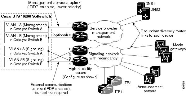
Figure 1-8 shows an example of communication paths between the Cisco BTS 10200 Softswitch and NEs in the managed network. The initial software configuration of the Cisco BTS 10200 Softswitch enables it to communicate with external NEs.
Caution 
To ensure proper functioning of the network, you must configure the network with at least the level of redundancy, diverse routing, and IRDP functionality shown in this drawing. Otherwise, a single point of failure could cause a traffic interruption.
Figure 1-8 Uplinks and Communications Paths to NEs in the Managed Network
1.
IRDP on the management network routers must be set at a lower priority that the IRDP level on the signaling network.
2.
The uplinks are used as follows:
a.
Two uplinks for management services (via connection modes such as SSH and SFTP), DNS services, and outbound billing (via FTP and SFTP).
b.
Four uplinks for external communications for VoIP signaling based on protocols such as MGCP, SIP, H.323, COPS, SIGTRAN, and so forth.
Note
The four signaling uplinks must be connected to the appropriate internal VLANs of the Cisco BTS 10200 Softswitch as shown in Figure 1-8.
3.
To support full system redundancy, you must connect the six external uplinks to four separate routers as shown in Figure 1-8. Furthermore, you must also connect the routers to separate networks with diverse routing paths to the applicable external NEs and services (such as DNSs, ITPs, media gateways, and announcement servers).
Caution 
If each of the external uplinks is not connected as described in Note #
3., a single point of failure could cause a traffic interruption.
4.
The Cisco BTS 10200 Softswitch does not store or use absolute IP addresses. Instead, it locates network connections by looking up domain names on the service provider domain name server (DNS). The service provider DNS translates the domain names into IP addresses. During software installation, the Cisco BTS 10200 Softswitch is configured with the data it needs to communicate with the service provider DNS. This configuration data is stored in the opticall.cfg file, and some critical domain names are also populated in the etc/hosts file in each host machine. To ensure redundancy of the DNS lookup function in the event of a network outage, Cisco recommends that two (redundant) DNS units be deployed in the service provider network, and that the two DNSs be reachable via separate networks with diverse routing paths. Cisco recommends that you place the DNSs behind a load balancer so that a single IP address is exported to clients such as the Cisco BTS 10200 Softswitch.

Caution 
If both DNS servers become unreachable, a traffic interruption may occur.