Table Of Contents
About Cisco Validated Design (CVD) Program
Oracle Database 11g R2 RAC on FlexPod with Oracle Direct NFS Client
Main Components of the Cisco Unified Computing System
NetApp Storage Technologies and Benefits
NetApp OnCommand System Manager 2.0
Oracle Database 11g Direct NFS Client
Hardware and Software Used for this Solution
Cisco UCS Networking and NetApp NFS Storage Topology
Cisco UCS Manager Configuration Overview
Configuring Fabric Interconnects for Blade Discovery
Configuring LAN and SAN on Cisco UCS Manager
Configure vNIC and vHBA Templates
Configure Ethernet Uplink Port Channels
Create Server Boot Policy for SAN Boot
Service Profile Creation and Association to Cisco UCS Blades
Create Service Profile Template
Create Service Profiles from Service Profile Templates
Associating a Service Profile to Servers
Cisco Nexus 5548UP Configuration
Configure NPIV and FCoE Features
Configure Fiber Channel Fabric Zoning for SAN Boot
Setting up VLAN and VSAN Configuration
VLAN Configuration for Cisco Nexus 5548 Fabric A
VSAN Configuration for Cisco Nexus 5548 Fabric A
Configuring the Virtual Port Channel for Oracle Data Network and Storage Network
Configure Virtual Port Channel on Cisco Nexus 5548
Configure the Virtual Port Channel for the Data Network
Port Channel Configuration on the Cisco Nexus 5548 Fabric-A
Port Channel Configuration on the Cisco Nexus 5548 Fabric-B
Configure Virtual Port Channel for NFS Storage Network
Port Channel Configuration on the Cisco Nexus 5548 Fabric-A
Port Channel Configuration on the Cisco Nexus 5548 Fabric-B
Setting Up Jumbo Frames on the Cisco Nexus 5548UP
NetApp Storage Configuration Overview
Storage Configuration for SAN Boot
Create and Configure Aggregate, Volumes and Boot LUNs
Create and Configure Initiator Group (igroup) and LUN Mapping
Storage Configuration for NFS Storage Network:
Create and Configure Aggregate and Volumes
Create and Configure VIF Interface (Multimode)
Cisco UCS Blade Servers and Stateless Computing with SAN Boot
Summary for Boot from SAN Configuration
OS Installation Steps and Recommendations
Oracle Database 11g R2 GRID Infrastructure with RAC Option Deployment
Installing Oracle Database 11g R2 RAC
Workload and Database Configuration
Destructive and Hardware Failover Tests
Appendix A—Nexus 5548 UP Fabric Zoning Configuration
Appendix B—Cisco Nexus 5548UP Switch Running Configuration
FlexPod Data Center with Oracle Database 11g R2 RAC with 7-ModeDeployment Guide for FlexPod with Oracle Database 11g R2 RAC with Oracle Direct NFS ClientLast Updated: November 22, 2013
Building Architectures to Solve Business Problems
About Cisco Validated Design (CVD) Program
The CVD program consists of systems and solutions designed, tested, and documented to facilitate faster, more reliable, and more predictable customer deployments. For more information visit
http://www.cisco.com/go/designzone.
ALL DESIGNS, SPECIFICATIONS, STATEMENTS, INFORMATION, AND RECOMMENDATIONS (COLLECTIVELY, "DESIGNS") IN THIS MANUAL ARE PRESENTED "AS IS," WITH ALL FAULTS. CISCO AND ITS SUPPLIERS DISCLAIM ALL WARRANTIES, INCLUDING, WITHOUT LIMITATION, THE WARRANTY OF MERCHANTABILITY, FITNESS FOR A PARTICULAR PURPOSE AND NONINFRINGEMENT OR ARISING FROM A COURSE OF DEALING, USAGE, OR TRADE PRACTICE. IN NO EVENT SHALL CISCO OR ITS SUPPLIERS BE LIABLE FOR ANY INDIRECT, SPECIAL, CONSEQUENTIAL, OR INCIDENTAL DAMAGES, INCLUDING, WITHOUT LIMITATION, LOST PROFITS OR LOSS OR DAMAGE TO DATA ARISING OUT OF THE USE OR INABILITY TO USE THE DESIGNS, EVEN IF CISCO OR ITS SUPPLIERS HAVE BEEN ADVISED OF THE POSSIBILITY OF SUCH DAMAGES.
THE DESIGNS ARE SUBJECT TO CHANGE WITHOUT NOTICE. USERS ARE SOLELY RESPONSIBLE FOR THEIR APPLICATION OF THE DESIGNS. THE DESIGNS DO NOT CONSTITUTE THE TECHNICAL OR OTHER PROFESSIONAL ADVICE OF CISCO, ITS SUPPLIERS OR PARTNERS. USERS SHOULD CONSULT THEIR OWN TECHNICAL ADVISORS BEFORE IMPLEMENTING THE DESIGNS. RESULTS MAY VARY DEPENDING ON FACTORS NOT TESTED BY CISCO.
CCDE, CCENT, Cisco Eos, Cisco Lumin, Cisco Nexus, Cisco StadiumVision, Cisco TelePresence, Cisco WebEx, the Cisco logo, DCE, and Welcome to the Human Network are trademarks; Changing the Way We Work, Live, Play, and Learn and Cisco Store are service marks; and Access Registrar, Aironet, AsyncOS, Bringing the Meeting To You, Catalyst, CCDA, CCDP, CCIE, CCIP, CCNA, CCNP, CCSP, CCVP, Cisco, the Cisco Certified Internetwork Expert logo, Cisco IOS, Cisco Press, Cisco Systems, Cisco Systems Capital, the Cisco Systems logo, Cisco Unity, Collaboration Without Limitation, EtherFast, EtherSwitch, Event Center, Fast Step, Follow Me Browsing, FormShare, GigaDrive, HomeLink, Internet Quotient, IOS, iPhone, iQuick Study, IronPort, the IronPort logo, LightStream, Linksys, MediaTone, MeetingPlace, MeetingPlace Chime Sound, MGX, Networkers, Networking Academy, Network Registrar, PCNow, PIX, PowerPanels, ProConnect, ScriptShare, SenderBase, SMARTnet, Spectrum Expert, StackWise, The Fastest Way to Increase Your Internet Quotient, TransPath, WebEx, and the WebEx logo are registered trademarks of Cisco Systems, Inc. and/or its affiliates in the United States and certain other countries.
All other trademarks mentioned in this document or website are the property of their respective owners. The use of the word partner does not imply a partnership relationship between Cisco and any other company. (0809R)
© 2013 Cisco Systems, Inc. All rights reserved
Oracle RAC on FlexPod
Executive Summary
Data powers essentially every operation in a modern enterprise, from keeping the supply chain operating efficiently to managing relationships with customers. Database administrators and their IT departments face many challenges that demand needs for a simplified deployment and operation model providing high performance, availability and lower total cost of ownership (TCO). Cisco Validated Designs (CVD) can help you deploy data center applications in a wide range of operating environments including mission critical workloads. This CVD describes how the Cisco Unified Computing System™ (Cisco UCS®) can be used in conjunction with NetApp® FAS storage systems to implement an Oracle Real Application Clusters (RAC) solution that is an Oracle Certified Configuration. FlexPod® components are integrated and standardized to help you eliminate the guesswork and achieve timely, repeatable, and consistent deployments. FlexPod has been optimized to run a variety of mixed workloads and while offering flexible yet robust design configurations. Customers are generally able to accelerate their transition with the FlexPod data center solution, which integrates disparate compute, storage, and network components into a single architecture that scales to fit a variety of virtualized and non-virtualized customer environments.
The key benefits of FlexPod deployments are:
•
Single platform from industry leaders in networking, computing, and storage.
•
•
•
For more information on NetApp FlexPod architecture, visit
http://www.netapp.com/us/technology/flexpod/
Target Audience
This document is intended to assist solution architects, project managers, infrastructure managers, sales engineers, field engineers, and consultants in planning, designing, and deploying Oracle Database 11g R2 RAC hosted on FlexPod. This document assumes that the reader has an architectural understanding of the Cisco Unified Computing System, Oracle Database 11gR2 GRID Infrastructure, Oracle Real Application Clusters, NetApp storage systems, and related software.
Purpose of this Guide
This FlexPod CVD demonstrates how enterprises can apply best practices to deploy Oracle Database 11g R2 RAC using Cisco Unified Computing System, Cisco Nexus family switches, and NetApp FAS storage systems. This validation effort exercised typical Online transaction processing (OLTP) and Decision-support systems (DSS) workloads to ensure expected stability, performance and resiliency design as demanded by mission critical data center deployments.
Business Needs
Business applications are moving into integrated stacks consisting of compute, network, and storage. This FlexPod solution helps to reduce costs and complexity of a traditional Oracle Database 11g R2 RAC deployment. Following business needs for Oracle Database 11g R2 RAC deployments are addressed by this solution.
•
•
•
Solution Overview
Oracle Database 11g R2 RAC on FlexPod with Oracle Direct NFS Client
This solution provides an end-to-end architecture with Cisco Unified Computing System, Oracle, and NetApp technologies and demonstrates the FlexPod configuration benefits for running Oracle Database 11g R2 RAC with Cisco VICs (Virtual Interface Card) and Oracle Direct NFS Client.
The following infrastructure and software components are used for this solution:
•
•
•
•
•
•
The following is the solution architecture connectivity layout for this FlexPod deployment.
Figure 1 Solution Architecture
Technology Overview
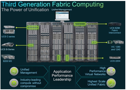
This section describes the Cisco Unified Computing System (Figure 2).
Figure 2 Third Generation Fabric Computing
The Cisco Unified Computing System is a third-generation data center platform that unites computing, networking, storage access, and virtualization resources into a cohesive system designed to reduce TCO and increase business agility. The system integrates a low-latency, lossless 10 Gigabit Ethernet (10GbE) unified network fabric with enterprise-class, x86-architecture servers. The system is an integrated, scalable, multi-chassis platform in which all resources participate in a unified management domain that is controlled and managed centrally.
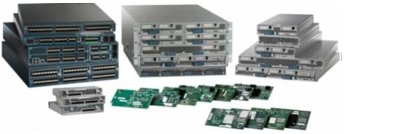
Main Components of the Cisco Unified Computing System
The main components of the Cisco Unified Computing System are as follows:
•
•
•
•
The Cisco Unified Computing System is designed to deliver:
•
•
•
•
•
Figure 3 Components of Cisco Unified Computing System
Cisco UCS Blade Chassis
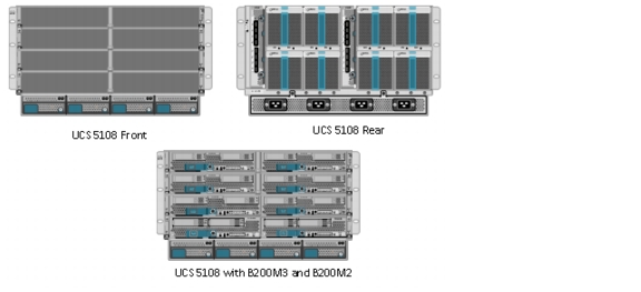
The Cisco UCS 5100 Series Blade Server Chassis (Figure 4) is a crucial building block of the Cisco Unified Computing System, delivering a scalable and flexible blade server chassis.
The Cisco UCS 5108 Blade Server Chassis is six rack units (6RU) high and can mount in an industry-standard 19-inch rack. A single chassis can house up to eight half-width Cisco UCS B-Series Blade Servers and can accommodate both half-width and full-width blade form factors.
Four single-phase, hot-swappable power supplies are accessible from the front of the chassis. These power supplies are 92 percent efficient and can be configured to support non-redundant, N+ 1 redundant and grid-redundant configurations. The rear of the chassis contains eight hot-swappable fans, four power connectors (one per power supply), and two I/O bays for Cisco UCS 2208 XP Fabric Extenders.
A passive mid-plane provides up to 40 Gbps of I/O bandwidth per server slot and up to 80 Gbps of I/O bandwidth for two slots. The chassis is capable of supporting future 80 Gigabit Ethernet standards.
Figure 4 Cisco Blade Server Chassis (front, back, and populated with blades)
Cisco UCS B200 M3 Blade Server
The Cisco UCS B200 M3 Blade Server is a half-width, two-socket blade server. The system uses two Intel Xeon® E5-2600 Series Processors, up to 384 GB of DDR3 memory, two optional hot-swappable small form factor (SFF) serial attached SCSI (SAS) disk drives, and two VIC adapters that provides up to 80 Gbps of I/O throughput. The server balances simplicity, performance, and density for production-level virtualization and other mainstream data center workloads.
Figure 5 Cisco UCS B200 M3 Blade Server
Cisco UCS Virtual Interface Card 1240
A Cisco innovation, the Cisco UCS VIC 1240 is a four-port 10 Gigabit Ethernet, FCoE-capable modular LAN on motherboard (mLOM) designed exclusively for the M3 generation of Cisco UCS B-Series Blade Servers. When used in combination with an optional port expander, the Cisco UCS VIC 1240 capabilities can be expanded to eight ports of 10 Gigabit Ethernet.
Cisco UCS 6248UP Fabric Interconnect
The Fabric interconnects provide a single point for connectivity and management for the entire system. Typically deployed as an active-active pair, the system's fabric interconnects integrate all components into a single, highly-available management domain controlled by Cisco UCS Manager. The fabric interconnects manage all I/O efficiently and securely at a single point, resulting in deterministic I/O latency regardless of a server or virtual machine's topological location in the system.
Cisco UCS 6200 Series Fabric Interconnects support the system's 80-Gbps unified fabric with low-latency, lossless, cut-through switching that supports IP, storage, and management traffic using a single set of cables. The fabric interconnects feature virtual interfaces that terminate both physical and virtual connections equivalently, establishing a virtualization-aware environment in which blade, rack servers, and virtual machines are interconnected using the same mechanisms. The Cisco UCS 6248UP is a 1-RU fabric interconnect that features up to 48 universal ports that can support 80 Gigabit Ethernet, Fibre Channel over Ethernet, or native Fibre Channel connectivity.
Figure 6 Cisco UCS 6248UP 20-Port Fabric (front and back)
Cisco UCS Manager
Cisco UCS Manager is an embedded, unified manager that provides a single point of management for Cisco Unified Computing System. Cisco UCS Manager can be accessed through an intuitive GUI, a command-line interface (CLI), or the comprehensive open XML API. It manages the physical assets of the server and storage and LAN connectivity, and it is designed to simplify the management of virtual network connections through integration with several major hypervisor vendors. It provides IT departments with the flexibility to allow people to manage the system as a whole, or to assign specific management functions to individuals based on their roles as managers of server, storage, or network hardware assets. It simplifies operations by automatically discovering all the components available on the system and enabling a stateless model for resource use.
Some of the key elements managed by Cisco UCS Manager include:
•
•
•
•
•
•
Cisco Unified Computing System is designed from the start to be programmable and self-integrating. A server's entire hardware stack, ranging from server firmware and settings to network profiles, is configured through model-based management. With Cisco virtual interface cards (VICs), even the number and type of I/O interfaces is programmed dynamically, making every server ready to power any workload at any time.
With model-based management, administrators manipulate a desired system configuration and associate a model's policy driven service profiles with hardware resources, and the system configures itself to match requirements. This automation accelerates provisioning and workload migration with accurate and rapid scalability. The result is increased IT staff productivity, improved compliance, and reduced risk of failures due to inconsistent configurations. This approach represents a radical simplification compared to traditional systems, reducing capital expenditures (CAPEX) and operating expenses (OPEX) while increasing business agility, simplifying and accelerating deployment, and improving performance.
Cisco UCS Service Profiles
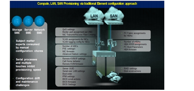
Figure 7 show the traditional provisioning approach.
Figure 7 Compute, LAN, SAN Provisioning via Traditional Provisional Approach
A server's identity is made up of many properties such as UUID, boot order, IPMI settings, BIOS firmware, BIOS settings, etc. There are many areas that need to be configured to give the server its identity and make it unique from every other server within your data center. Some of these parameters are kept in the hardware of the server itself (like BIOS firmware version, BIOS settings, boot order, FC boot settings, etc.) while some settings are kept on your network and storage switches (like VLAN assignments, FC fabric assignments, QoS settings, ACLs, etc.).
Lengthy deployment cycles
•
•
•
Response time to business needs
•
•
•
Limited OS and application mobility
•
•
Cisco Unified Computing System has uniquely addressed these challenges with the introduction of service profiles that enables integrated, policy based infrastructure management. UCS Service Profiles hold the DNA for nearly all configurable parameters required to set up a physical server. A set of user defined policies (rules) allow quick, consistent, repeatable, and secure deployments of UCS servers.
Figure 8 Cisco UCS Service Profiles—Integration and Management
Cisco UCS Service Profiles contain values for a server's property settings, including virtual network interface cards (vNICs), MAC addresses, boot policies, firmware policies, fabric connectivity, external management, and high availability information. By abstracting these settings from the physical server into a Cisco Service Profile, the Service Profile can then be deployed to any physical compute hardware within the Cisco UCS domain. Furthermore, Service Profiles can, at any time, be migrated from one physical server to another. This logical abstraction of the server personality separates the dependency of the hardware type or model and is a result of Cisco's unified fabric model (rather than overlaying software tools on top).
This innovation is still unique in the industry despite competitors claiming to offer similar functionality. In most cases, these vendors must rely on several different methods and interfaces to configure these server settings. Furthermore, Cisco is the only hardware provider to offer a truly unified management platform, with UCS Service Profiles and hardware abstraction capabilities extending to both blade and rack servers.
Some of key features and benefits of UCS service profiles are discussed below.
Service Profiles and Templates
A service profile contains configuration information about the server hardware, interfaces, fabric connectivity, and server and network identity. The Cisco UCS Manager provisions servers utilizing service profiles. The UCS Manager implements a role-based and policy-based management focused on service profiles and templates. A service profile can be applied to any blade server to provision it with the characteristics required to support a specific software stack. A service profile allows server and network definitions to move within the management domain, enabling flexibility in the use of system resources.
Service profile templates are stored in the Cisco UCS 6200 Series Fabric Interconnects for reuse by server, network, and storage administrators. Service profile templates consist of server requirements and the associated LAN and SAN connectivity. Service profile templates allow different classes of resources to be defined and applied to a number of resources, each with its own unique identities assigned from predetermined pools.
The Cisco UCS Manager can deploy the service profile on any physical server at any time. When a service profile is deployed to a server, the Cisco UCS Manager automatically configures the server, adapters, Fabric Extenders, and Fabric Interconnects to match the configuration specified in the service profile. A service profile template parameterizes the UIDs that differentiate between server instances.
This automation of device configuration reduces the number of manual steps required to configure servers, Network Interface Cards (NICs), Host Bus Adapters (HBAs), and LAN and SAN switches.
Programmatically Deploying Server Resources
Cisco UCS Manager provides centralized management capabilities, creates a unified management domain, and serves as the central nervous system of the Cisco Unified Computing System. Cisco UCS Manager is embedded device management software that manages the system from end-to-end as a single logical entity through an intuitive GUI, CLI, or XML API. Cisco UCS Manager implements role- and policy-based management using service profiles and templates. This construct improves IT productivity and business agility. Now infrastructure can be provisioned in minutes instead of days, shifting IT's focus from maintenance to strategic initiatives.
Dynamic Provisioning
Cisco UCS resources are abstract in the sense that their identity, I/O configuration, MAC addresses and WWNs, firmware versions, BIOS boot order, and network attributes (including QoS settings, ACLs, pin groups, and threshold policies) all are programmable using a just-in-time deployment model.. A service profile can be applied to any blade server to provision it with the characteristics required to support a specific software stack. A service profile allows server and network definitions to move within the management domain, enabling flexibility in the use of system resources. Service profile templates allow different classes of resources to be defined and applied to a number of resources, each with its own unique identities assigned from predetermined pools.
Cisco Nexus 5548UP Switch
The Cisco Nexus 5548UP is a 1RU 1 Gigabit and 10 Gigabit Ethernet switch offering up to 960 gigabits per second throughput and scaling up to 48 ports. It offers 32 1/10 Gigabit Ethernet fixed enhanced Small Form-Factor Pluggable (SFP+) Ethernet/FCoE or 1/2/4/8-Gbps native FC unified ports and three expansion slots. These slots have a combination of Ethernet/FCoE and native FC ports.
Figure 9 Cisco Nexus 5548UP Switch
The Cisco Nexus 5548UP Switch delivers innovative architectural flexibility, infrastructure simplicity, and business agility, with support for networking standards. For traditional, virtualized, unified, and high-performance computing (HPC) environments, it offers a long list of IT and business advantages, including:
Architectural Flexibility
•
•
•
•
–
–
–
Infrastructure Simplicity
•
•
•
•
•
Business Agility
•
•
•
Specifications at-a-Glance
•
•
•
•
NetApp Storage Technologies and Benefits
NetApp storage platform can handle different type of files and data from various sources-including user files, e-mail, and databases. Data ONTAP is the fundamental NetApp software platform that runs on all NetApp storage systems. Data ONTAP is a highly optimized, scalable operating system that supports mixed NAS and SAN environments and a range of protocols, including Fiber Channel, iSCSI, FCoE, NFS, and CIFS. The platform includes the Write Anywhere File Layout (WAFL®) file system and storage virtualization capabilities. By leveraging the Data ONTAP platform, the NetApp Unified Storage Architecture offers the flexibility to manage, support, and scale to different business environments by using a common knowledge base and tools. This architecture enables users to collect, distribute, and manage data from all locations and applications at the same time. This allows the investment to scale by standardizing processes, cutting management time, and increasing availability. Figure 10 shows the various NetApp Unified Storage Architecture platforms.
Figure 10 NetApp Unified Storage Architecture Platforms
The NetApp storage hardware platform used in this solution is the FAS3270A. The FAS3200 series is an excellent platform for primary and secondary storage for an Oracle Database 11g R2 GRID Infrastructure deployment.
A number of NetApp tools and enhancements are available to augment the storage platform. These tools assist in deployment, backup, recovery, replication, management, and data protection. This solution makes use of a subset of these tools and enhancements.
Storage Architecture
The storage design for any solution is a critical element that is typically responsible for a large percentage of the solution's overall cost, performance, and agility.
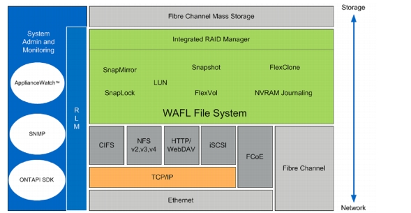
The basic architecture of the storage system's software is shown in the figure below. A collection of tightly coupled processing modules handles CIFS, FCP, FCoE, HTTP, iSCSI, and NFS requests. A request starts in the network driver and moves up through network protocol layers and the file system, eventually generating disk I/O, if necessary. When the file system finishes the request, it sends a reply back to the network. The administrative layer at the top supports a command line interface (CLI) similar to UNIX® that monitors and controls the modules below. In addition to the modules shown, a simple real-time kernel provides basic services such as process creation, memory allocation, message passing, and interrupt handling.
The networking layer is derived from the same Berkeley code used by most UNIX systems, with modifications made to communicate efficiently with the storage appliance's file system. The storage appliance provides transport-independent seamless data access using block- and file-level protocols from the same platform. The storage appliance provides block-level data access over an FC SAN fabric using FCP and over an IP-based Ethernet network using iSCSI. File access protocols such as NFS, CIFS, HTTP, or FTP provide file-level access over an IP-based Ethernet network.
Figure 11 NetApp Controller Storage Architecture
RAID-DP
RAID-DP® is NetApp's implementation of double-parity RAID 6, which is an extension of NetApp's original Data ONTAP WAFL® RAID 4 design. Unlike other RAID technologies, RAID-DP provides the ability to achieve a higher level of data protection without any performance impact, while consuming a minimal amount of storage. For more information on RAID-DP, see http://www.netapp.com/us/products/platform-os/raid-dp.html.
Snapshot
NetApp Snapshot technology provides zero-cost, near-instantaneous backup and point-in-time copies of the volume or LUN by preserving the Data ONTAP WAFL consistency points.
Creating Snapshot copies incurs minimal performance effect because data is never moved, as it is with other copy-out technologies. The cost for Snapshot copies is at the rate of block-level changes and not 100% for each backup, as it is with mirror copies. Using Snapshot can result in savings in storage cost for backup and restore purposes and opens up a number of efficient data management possibilities.
FlexVol
NetApp® FlexVol® storage-virtualization technology enables you to respond to changing storage needs fast, lower your overhead, avoid capital expenses, and reduce disruption and risk. FlexVol technology aggregates physical storage in virtual storage pools, so you can create and resize virtual volumes as your application needs change.
With FlexVol you can improve-even double-the utilization of your existing storage and save the expense of acquiring more disk space. In addition to increasing storage efficiency, you can improve I/O performance and reduce bottlenecks by distributing volumes across all available disk drives.
NetApp OnCommand System Manager 2.0
System Manager is a powerful management tool for NetApp storage that allows administrators to manage a single NetApp storage system as well as clusters, quickly and easily.
Some of the benefits of the System Manager Tool are:
•
•
•
•
•
•
Oracle Database 11g R2 RAC
Oracle Database 11g Release 2 provides the foundation for IT to successfully deliver more information with higher quality of service, reduce the risk of change within IT, and make more efficient use of IT budgets.
Oracle Database 11g R2 Enterprise Edition provides industry-leading performance, scalability, security, and reliability on a choice of clustered or single-servers with a wide range of options to meet user needs. Grid computing relieves users from concerns about where data resides and which computer processes their requests. Users request information or computation and have it delivered - as much as they want, whenever they want. For a DBA, the grid is about resource allocation, information sharing, and high availability. Oracle Database with Real Application Clusters provide the infrastructure for your database grid. Automatic Storage Management provides the infrastructure for a storage grid. Oracle Enterprise Manager Grid Control provides you with holistic management of your grid.
Oracle Database 11g Direct NFS Client
Direct NFS client is an Oracle developed, integrated, and optimized client that runs in user space rather than within the operating system kernel. This architecture provides for enhanced scalability and performance over traditional NFS v3 clients. Unlike traditional NFS implementations, Oracle supports asynchronous I/O across all operating system environments with Direct NFS client. In addition, performance and scalability are dramatically improved with its automatic link aggregation feature. This allows the client to scale across as many as four individual network pathways with the added benefit of improved resiliency when Network connectivity is occasionally compromised. It also allows Direct NFS clients to achieve near block level Performance. For more information on Direct NFS Client comparison to block protocols, see http://media.netapp.com/documents/tr-3700.pdf.
Design Topology
This section presents physical and logical high-level design considerations for Cisco UCS networking and computing on NetApp storage for Oracle Database 11g R2 RAC deployments.
Hardware and Software Used for this Solution
Table 1 shows the software and hardware used for Oracle Database 11g R2 GRID Infrastructure with RAC Option Deployment.
Table 1 Software and Hardware for Oracle Database 11g R2 GRID Infrastructure with RAC Option Deployment
Cisco UCS Networking and NetApp NFS Storage Topology
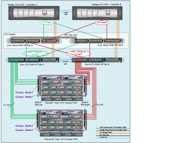
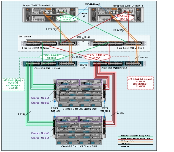
This section explains Cisco UCS networking and computing design considerations when deploying Oracle Database 11g R2 RAC in an NFS Storage Design. In this design, the NFS traffic is isolated from the regular management and application data network using the same Cisco UCS infrastructure by defining logical VLAN networks to provide better data security. Figure below, presents a detailed view of the physical topology, and some of the main components of Cisco UCS in an NFS network design.
Figure 12 Cisco UCS Networking and NFS Storage Network Topology
As shown above, a pair of Cisco UCS 6248UP fabric interconnects carries both storage and network traffic from the blades with the help of Cisco Nexus 5548UP switch. The 8GB Fiber channel traffic (shown in green lines) leaves the UCS Fabrics through Nexus5548 Switches to NetApp Array to boot the Operating system from SAN environment. This is a typical configuration that can be deployed in a customer's environment or customers can choose to boot other methods such as local disk boot as per business requirements. Boot from SAN is a recommended option to enable stateless computing for UCS servers. From the block diagram it looks like all 8GB FC links are blocking? As described it appears there is no valid path to the SAN.
Both the fabric interconnect and the Cisco Nexus 5548UP switch are clustered with the peer link between them to provide high availability. Two virtual Port Channels (vPCs) are configured to provide public network, private network and storage access paths for the blades to northbound switches. Each vPC has VLANs created for application network data, NFS storage data, and management data paths. For more information about vPC configuration on the Cisco Nexus 5548UP Switch, see http://www.cisco.com/en/US/prod/collateral/switches/ps9441/ps9670/configuration_guide_c07-543563.html.
As illustrated in picture above, Eight (Four per chassis) links go to Fabric Interconnect "A" (ports 1 through 8). Similarly, Eight links go to Fabric Interconnect B. Fabric Interconnect-A links are used for Oracle Public network & NFS Storage Network traffic and Fabric Interconnect-B links are used for Oracle private interconnect traffic and NFS Storage network traffic.
Note
Cisco UCS Manager Configuration Overview
The following are the high-level steps involved for a Cisco UCS configuration:
1.
a.
2.
a.
b.
c.
d.
3.
a.
b.
c.
4.
a.
b.
c.
d.
e.
5.
6.
Details for each step are discussed in subsequent sections below.
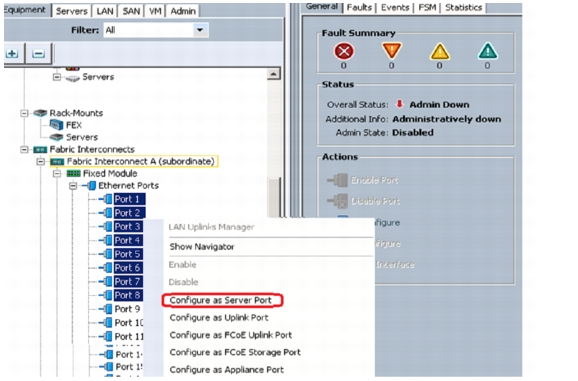
Configuring Fabric Interconnects for Blade Discovery
Cisco UCS 6248 UP Fabric Interconnects are configured for redundancy. It provides resiliency in case of failures. The first step is to establish connectivity between the blades and fabric interconnects.
Configuring Server ports
1.
2.
3.
4.
5.
6.
Configuring LAN and SAN on Cisco UCS Manager
Perform the LAN and SAN configuration steps in the Cisco UCS Manager as shown in the following section.
Configure and Enable Ethernet LAN uplink Ports
1.
2.
3.
4.
As shown in the screenshot above, we selected Port 17 and 18 on Fabric interconnect A and configured them as Ethernet Uplink ports. Repeat the same step on Fabric interconnect B to configure Port 17 and 18 as Ethernet uplink ports. We will use these ports to create Port-channels in later sections.
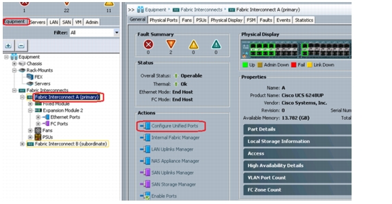
Configure and Enable FC SAN Uplink Ports
1.
2.
3.
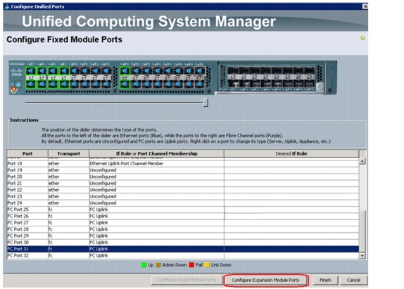
The Configure Expansion Module Ports displays.
4.
XXXX
You can use the slider to select a set of ports. Right Click on the selected ports and click on "Configure as FC Uplink Port" and Click on Finish button to Save the configuration changes.
Repeat for same steps on Fabric Interconnect B switch to enable LAN uplink and FC uplink ports. Next step is to configure VLANs for this configuration. Before we get into vLAN configuration, here are a couple of Best practices for Oracle RAC configuraion.
Important Oracle RAC Best Practices and Recommendations for vLANs and vNIC Configuration
For Direct NFS clients running on Linux, best practices recommend always to use multipaths in separate subnets. If multiple paths are configured in the same subnet, the operating system invariably picks the first available path from the routing table. All traffic flows through this path and the load balancing and scaling do not work as expected. Please refer to Oracle metalink note 822481.1 for more details.
Note
Oracle Grid Infrastructure can activate a maximum of four private network adapters for availability and bandwidth requirements. In our testing, we observed that a single Cisco UCS 10GE private vNIC configured with failover did not require multiple vnics configuration from bandwidth and availability perspective. If you want to configure multiple vnics for your private interconnect ,we strongly recommend using a separate VLAN for each private vNIC. As a general best practice, it is a good idea to localize all private interconnect traffic to single fabric interconnect. For more information on Oracle HAIP, please refer to Oracle metalink note 1210883.1.
When you have decided on VLAN and vNICs, we are ready to configure vLANs for this setup.
Configure VLAN
1.
2.
In the screenshot above, we have highlighted VLAN 10 creation for Private network. It is also very important that you create both VLANs as global across both fabric interconnects. This way, VLAN identity is maintained across the fabric interconnects in case of NIC failover.
Repeat the process for creating Public vlans & Storage vlans when using Oracle HAIP feature, you may have to configure additional vlans to be associated with additional vnics as well.
Here is the summary of VLANs once you complete VLAN creation.
•
•
•
Note
The figure below summarizes all the VLANs for Public and Private network and Storage access.
Figure 13 VLAN Summary
Configure VSAN
In Cisco UCS manager, click SAN > SAN Cloud > VSANs and right-click to Create VSAN. In this study we created VSAN 25 for SAN Boot.
Figure 14 Configuring VSAN in Cisco UCS Manager
In this study, we created VSAN Name as "SAN boot" and Selected "Common/Global" to create VSAN on both the Fabrics and specified VSAN ID as "25" and FCoE VLAN ID as "25".
Note
Figure 15 VSAN Summary
Configure Pools
When VLANs and VSAN are created, we need to configure pools for UUID, MAC Addresses, Management IP and WWN.
UUID Pool Creation
In Cisco UCS Manager, click Servers > Pools > UUID Suffix Pools and right-click to "Create UUID Suffix Pool", create a new pool.
Figure 16 Create UUID Pools
As shown in Figure 17, we created UUID Pool as OraFlex-UUID-Pools.
Figure 17 Post UUID Pool Creation
IP Pool and MAC Pool Creation
In Cisco UCS Manager, click LAN > Pools > IP Pools and right-click to "Create IP Pool Ext-mgmt". We created ext-mgmt IP pool as shown below. Next, click MAC Pools to "Create MAC Pools". We created OraFlex-MAC-Pools for the all vNIC MAC addresses.
Figure 18 Create IP Pool and MAC Pool
The IP pools will be used for console management, while MAC addresses for the vnics being carved out later.
WWNN Pool and WWPN pool Creation
In Cisco UCS Manager, click SAN > Pools > WWNN Pools and right-click to "Create WWNN Pools". Next, click WWPN Pools to "Create WWPN Pools". These WWNN and WWPN entries will be used for Boot from SAN configuration.
We created OraFlex-WWPN-Pools and OraFlex_WWNN-Pools as shown below.
Figure 19 Create WWNN and WWPN Pool
Pool creation is complete. The next step is to create vNIC and vHBA templates.
Configure vNIC and vHBA Templates
Create a vNIC Template
In Cisco UCS Manager, click LAN > Policies > vNIC templates and right-click "Create vNIC Template."
Figure 20 Create vNIC Template
We created four vNIC templates for this Oracle RAC on FlexPod configuration: one for public network, one for private network and two for storage network. The private network is for Oracle RAC internal heartbeat and cache fusion traffic while Public network for external clients like middle tiers and ssh sessions to the Oracle hosts. The storage networks are for NFS data traffic access of Oracle DSS and OLTP database volumes.
Create Private vNIC Template
For Oracle private network vNIC template, we strongly recommend to set 9000 MTU. We also will pin this template to Fabric B with vNIC failover enabled. For private vNICs derived from this template, all communication among those private vNICs will stay local to Fabric Interconnect B. In case, of a failure on Fabric B, the appropriate vNICs will failover to Fabric A. As shown in the screenshot below, please make sure to use OraFlex-MAC-Pools as the MAC Pool for MAC addresses.
Figure 21 Create Private vNIC Template
Create Public vNIC Template
Next, create a vNIC template for public network. We used MTU=1500 and OraFlex-MAC-Pools as the MAC Pool for this template. We selected "enable failover" for public network.
Figure 22 Create Public vNIC Template
Create Storage vNIC Template
For storage vNIC template, we used VLAN 20 and pinned it Fabric interconnect A. The vNICs derived from this template will drive database NFS traffic so we also used Jumbo frames (MTU=9000) as shown below.
Figure 23 Create Storage vNIC Template on Fabric A
Repeat the same process to create a storage vNIC template for Fabric B.
Figure 24 Create Storage vNIC Template on Fabric B
The following is the vNIC template summary after all necessary templates for this FlexPod configuration are created.
Figure 25 vNIC Template Summary
Create HBA Templates
In Cisco UCS Manager, click SAN > Policies > vHBA templates and right-click "Create vHBA Template."
Figure 26 Create vHBA Templates
We created two vHBA templates as vHBA1_FabA and vHBA2_FabB as shown below.
Next, we will configure Ethernet uplink port channels.
Configure Ethernet Uplink Port Channels
To configure Port Channels, click LAN > LAN Cloud > Fabric A > Port Channels and right-click "Create Port-Channel." Select the desired Ethernet Uplink ports configured earlier.
Repeat these steps to create Port Channels on Fabric B. In the current setup, we used ports 17 and 18 on Fabric A and configured as Port Channel 10. Similarly, ports 17 and 18 on Fabric B are configured to create Port Channel 11.
Figure 27 Configuring Port Channels
Ether Port Channel Details on Fabric A
Figure 28 Port Channel-10 Status and Properties
Ether Port Channel Details on Fabric B
Figure 29 Port Channel-11 Status and Properties
Create Server Boot Policy for SAN Boot
Navigate to Cisco UCS Manager > Servers > Policies > Boot Policies > right-click Create Boot Policy. From the Local devices "Add CD-ROM" and click vHBA's to "add SAN Boot" as shown below.
Figure 30 Cisco UCS Server Boot Policy
Note
When the above preparation steps are complete we are ready to create a service template from which the service profiles can be easily created.
Service Profile Creation and Association to Cisco UCS Blades
Service profile templates enable policy based server management that helps ensure consistent server resource provisioning suitable to meet predefined workload needs.
Create Service Profile Template
In Cisco UCS Manager, click Servers > Service Profile Templates > root and right-click root to "Create Service Profile Template."
Figure 31 Create Service Profile Template
Enter the template name and select the UUID Pool that was created earlier and move on to the next screen.
Figure 32 Identify Service Profile Template
Figure 33 Networking—LAN Configurtation
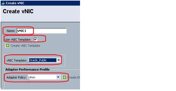
In the Networking page create vNICs; one on each fabric and associate them with the VLAN policies created earlier. Select expert mode, and click on add on the section that specifies add one or more vNICs that the server should use to connect to the LAN.
In the create vNIC page, select "Use vNIC template" and adapter policy as Linux. In the page below vNIC1 was selected for Oracle public network.
Figure 34 Creation of vNICs using vNIC Template
Similarly, create vNIC2 for private, vNIC3 for Storage side A, and VNIC4 for Storage Side B with appropriate vNIC template mapping for each vNIC.
Figure 35 Post vNIC Creation Using vNIC Template
When vNICs are created, you will need to create vHBA's.
In the storage page, select expert mode, choose the WWNN pool created earlier and click the Add button to create vHBA's.
Figure 36 Storage—SAN Configuration
We created two vHBA's:
•
•
Figure 37 Create vHBAs Using vHBA Template
Figure 38 Worldwide Node Name Assignment
For this FlexPod configuration, we used Cisco Nexus 5548UP for zoning so we will skip the zoning section and use default vNIC/vHBA placement.
Figure 39 vNIC/vHBA Placement
Server Boot Policy
In the Server Boot Order page, choose the Boot Policy created for SAN boot and click Next.
Figure 40 Configure Server Boot Policy During Service Profile Template Creation
Figure 41 Server Boot Order Assignment
The maintenance and server assignment policies were left to default in our configuration. However, they may vary from site to site depending on your work loads, best practices and policies.
Create Service Profiles from Service Profile Templates
In Cisco UCS Manager, click Servers > Service Profile Templates and right-click Create Service Profiles from Template.
Figure 42 Create Service Profile from Service Profile Template
We created four service profiles with the name prefix "B200M3-ORARAC-Node" as listed below:
•
•
•
•
Figure 43 Post Service Profiles Creation
Associating a Service Profile to Servers
As service profiles are created we are ready to associate them to the servers.
1.
2.
Repeat the same steps to associate the remaining three service profiles for the respective blade servers as shown below:
•
•
•
•
When you start associating the service profiles, the overall status will be shown as "Config"
Figure 44 Overall Status During Service Profile Association
Note
Figure 45 FSM (Final State Machine) Status During Service Profile Association
Make sure all the service profiles are associated as shown below.
Figure 46 Post Service Profile Association
Cisco Nexus 5548UP Configuration
The following are the general steps involved in Nexus 5548UP configuration.
1.
2.
3.
4.
a.
b.
c.
5.
In the following sections describe the steps in detail.
Configure NPIV and FCoE Features
If the NPIV feature is not enabled or if it is a new setup, enable the NPIV feature on the Cisco Nexus N5548 switches. The NPIV feature is required to register FLOGI (Fabric Login) of the Cisco UCS blade WWPN (Host Initiator).
Steps to enable NPIV and FCoE features on Cisco Nexus 5548 switch A:
N5548-Fab-A# config terminalN5548-Fab-A(config)# feature npivN5548-Fab-A(config)# feature fcoeRepeat the steps to enable the NPIV feature on Switch B.
Configure Fiber Channel Fabric Zoning for SAN Boot
Make sure you have (8 GB) SFP+ modules connected to the Nexus 5548UP ports. The port mode is set to AUTO as well as the speed is set to AUTO. Rate mode is "dedicated" and when everything is configured correctly.
Note
Table2 lists the plan for zones and their associated members that are used in the testing and discussed in this document. In the current setup, we used a total of 4 paths: 2 paths from each Fabrics and Cisco Nexus 5548's to the storage.
Table 2 Zones for Oracle RAC Node Setup
To find out the host adapter WWPN's for each of the HBA's, launch Cisco UCS Manager. From the Cisco UCS Manager, select the desired server from Equipment > chassis > servers > vHBAs menu.
The WWPN numbers for both HBAs for server 1 are illustrated above. In the current setup, we used a total of 4 paths: 2 paths from each Fabrics and Cisco Nexus 5548's to the storage. The details are shown below.
Setting up VLAN and VSAN Configuration
VLAN Configuration for Cisco Nexus 5548 Fabric A
VLAN 134 Configuration for Public trafficN5548-Fab-A# config terminalN5548-Fab-A(config)# VLAN 134N5548-Fab-A(config-VLAN)# name Oracle_RAC_Public_TrafficN5548-Fab-A(config-VLAN)# no shutdownN5548-Fab-A(config-VLAN)# exitVLAN 134 Configuration for Private trafficN5548-Fab-A(config)# VLAN 10N5548-Fab-A(config-VLAN)# name Oracle_RAC_Private_TrafficN5548-Fab-A(config-VLAN)# no ip igmp snoopingN5548-Fab-A(config-VLAN)# no shutdownN5548-Fab-A(config-VLAN)# exitVLAN 20 Configuration for storage trafficN5548-Fab-A(config)# VLAN 20N5548-Fab-A(config-VLAN)# name Storage_Traffic for ControllerAN5548-Fab-A(config-VLAN)# no shutdownN5548-Fab-A(config-VLAN)# exitVLAN 30 Configuration for storage trafficN5548-Fab-A(config)# VLAN 30N5548-Fab-A(config-VLAN)# name Storage_Traffic for ControllerBN5548-Fab-A(config-VLAN)# no shutdownN5548-Fab-A(config-VLAN)# exitN5548-Fab-B(config)# Copy running-config startup-configVSAN Configuration for Cisco Nexus 5548 Fabric A
N5548-Fab-A(config)# vsan databaseN5548-Fab-A(config-vsan-database)# vsan 25N5548-Fab-A(config-vsan-database)# vsan 25 interface fc 1/29-32N5548-Fab-A(config)# exitN5548-Fab-B(config)# Copy running-config startup-configRepeat the VLAN and VSAN configuration steps on Cisco Nexus 5548 Fabric B.
Configuring the Virtual Port Channel for Oracle Data Network and Storage Network
Configure Virtual Port Channel on Cisco Nexus 5548
Cisco Nexus 5548UP vPC configurations with the vPC domains and corresponding vPC names and IDs for Oracle Database Servers is as shown in Table 3. To provide Layer 2 and Layer 3 switching, a pair of Cisco Nexus 5548UP Switches with upstream switching are deployed, providing high availability in the event of failure to Cisco UCS to handle management, application, and Network storage data traffic. In the Cisco Nexus 5548UP switch topology, a single vPC feature is enabled to provide high availability, faster convergence in the event of a failure, and greater throughput.
Table 3 vPC Mapping for the Cisco Nexus 5548UP Switch
vPC Domain
vPC Name
vPC ID
1
Peer-Link
1
1
vPC-Public
17
1
vPC-Private
18
1
vPC-Storage1
20
1
vPC-Storage2
30
In the vPC design table, a single vPC domain, Domain ID 1 is created across Cisco Nexus 5548UP member switches to define vPCs to carry specific VLAN network traffic. In this topology, we defined 5 vPCs with IDs. vPC ID 1 is defined to Peer link communication between 2 x Nexus switches in Fabric A & B. vPC IDs 17 and 18 are defined for traffic from Cisco UCS fabric interconnects, and vPC IDs 20 and 30 are defined for NFS Storage traffic to NetApp Array. These vPCs are managed within the Cisco Nexus 5548UP, which connects Cisco UCS fabric interconnects and the NetApp storage system.
The following are the steps to configure vPC.
1.
N5548-Fab-A# config terminalN5548-Fab-A(config)#feature vpcN5548-Fab-A(config)#vpc domain 1N5548-Fab-A(config-vpc-domain)# peer-keepalive destination <Mgmt. IP Address of peer-N5548-B>N5548-Fab-A(config-vpc-domain)# exitN5548-Fab-A(config)# interface port-channel 1N5548-Fab-A(config-if)# switchport mode trunkN5548-Fab-A(config-if)# vpc peer-linkN5548-Fab-A(config-if)# switchport trunk allowed VLAN 1,10,134,20,30N5548-Fab-A(config-if)# spanning-tree port type networkN5548-Fab-A(config-if)# exitN5548-Fab-A(config)# interface Ethernet1/1N5548-Fab-A(config-if)# description Peer link connected to N5548B-Eth1/1N5548-Fab-A(config-if)# switchport mode trunkN5548-Fab-A(config-if)# switchport trunk allowed VLAN 1,10,20,30,134N5548-Fab-A(config-if)# channel-group 1 mode activeN5548-Fab-A(config-if)# no shutdownN5548-Fab-A(config-if)# exitN5548-Fab-A(config)# interface Ethernet1/2N5548-Fab-A(config-if)# description Peer link connected to N5548B-Eth1/2N5548-Fab-A(config-if)# switchport mode trunkN5548-Fab-A(config-if)# switchport trunk allowed VLAN 1,10,20,30,134N5548-Fab-A(config-if)# channel-group 1 mode activeN5548-Fab-A(config-if)# no shutdownN5548-Fab-A(config-if)# exitN5548-Fab-A(config)# copy running-config startup-config2.
N5548-Fab-B(config)# conf termN5548-Fab-B(config)# feature vpcN5548-Fab-B(config)# vpc domain 1N5548-Fab-B(config-vpc-domain# peer-keepalive destination <Mgmt. IP Address of peer-N5548-A>N5548-Fab-B(config-vpc-domain)# exitN5548-Fab-B(config)# interface port-channel 1N5548-Fab-B(config-if)# description Port-Channel for vPC Peer-linkN5548-Fab-B(config-if)# switchport mode trunkN5548-Fab-B(config-if)# vpc peer-linkN5548-Fab-B(config-if)# switchport trunk allowed VLAN 1,10,134,20,30N5548-Fab-B(config-if)# spanning-tree port type networkN5548-Fab-B(config-if)# exitN5548-Fab-B(config)# interface Ethernet1/1N5548-Fab-B(config-if)# description Peer link connected to N5548A-Eth1/1N5548-Fab-B(config-if)# switchport mode trunkN5548-Fab-B(config-if)# switchport trunk allowed VLAN 1,10,20,30,134N5548-Fab-B(config-if)# channel-group 1 mode activeN5548-Fab-B(config-if)# no shutdownN5548-Fab-B(config-if)# exitN5548-Fab-B(config)# interface Ethernet1/2N5548-Fab-B(config-if)# description Peer link connected to N5548A-Eth1/2N5548-Fab-B(config-if)# switchport mode trunkN5548-Fab-B(config-if)# switchport trunk allowed VLAN 1,10,20,30,134N5548-Fab-B(config-if)# channel-group 1 mode activeN5548-Fab-B(config-if)# no shutdownN5548-Fab-B(config-if)# exitN5548-Fab-B(config)# copy running-config startup-configConfigure the Virtual Port Channel for the Data Network
Table 4 shows vPC configuration details for Cisco UCS 6248UP Fabric Interconnects A and B with required vPC IDs, VLAN IDs, and Ethernet uplink ports.
Table 4 vPC Port Channel for the Cisco Nexus 5548UP Switch
On Cisco UCS Fabric Interconnect A, Ethernet uplink ports 17 and 18 are connected to Cisco Nexus 5548UP Fabric A (port 1/17) and Cisco Nexus 5548UP Fabric B (port 1/17), which are part of vPC ID 17 and have access to Oracle DB Public and Private VLAN IDs 134 and 10 & also have access to Storage Network VLAN IDs 20 & 30. The same configuration is replicated for vPC ID 18 on Fabric interconnect B, with ports 17 and 18 connected to port 8 of Cisco Nexus 5548UP Fabric A (port 1/18) and Cisco Nexus 5548UP Fabric B (port 1/18) and it has same access like Nexus 5548 Fabric A switch.
The following are the configuration details for the Cisco Nexus 5548UP switches.
Port Channel Configuration on the Cisco Nexus 5548 Fabric-A
N5548-Fab-A(config)# interface Port-channel 17N5548-Fab-A(config-if)# description Port-Channel for Fabric InterconnectAN5548-Fab-A(config-if)# switchport mode trunkN5548-Fab-A(config-if)# switchport trunk allowed VLAN 134,10,20,30N5548-Fab-A(config-if)# vPC 17N5548-Fab-A(config-if)# no shutdownN5548-Fab-A(config-if)# exitN5548-Fab-A(config)# interface Port-channel 18N5548-Fab-A(config-if)# description Port-Channel for Fabric InterconnectBN5548-Fab-A(config-if)# switchport mode trunkN5548-Fab-A(config-if)# switchport trunk allowed VLAN 134,10,20,30N5548-Fab-A(config-if)# vPC 18N5548-Fab-A(config-if)# no shutdownN5548-Fab-A(config-if)# exitN5548-Fab-A# config TerminalN5548-Fab-A(config)# interface eth 1/17N5548-Fab-A(config-if)# description Connection from Fabric Interconnect-A Eth1/17N5548-Fab-A(config-if)# channel-group 17 mode activeN5548-Fab-A(config-if)# no shutdownN5548-Fab-A(config-if)# exitN5548-Fab-A(config)# interface eth 1/18N5548-Fab-A(config-if)# description Connection from Fabric Interconnect-B Eth1/17N5548-Fab-A(config-if)# channel-group 18 mode activeN5548-Fab-A(config-if)# no shutdownN5548-Fab-A(config-if)# exitPort Channel Configuration on the Cisco Nexus 5548 Fabric-B
N5548-Fab-B(config)# interface Port-channel 17N5548-Fab-B(config-if)# description Port-Channel for Fabric InterconnectAN5548-Fab-B(config-if)# switchport mode trunkN5548-Fab-B(config-if)# switchport trunk allowed VLAN 134,10,20,30N5548-Fab-B(config-if)# vPC 17N5548-Fab-B(config-if)# no shutdownN5548-Fab-B(config-if)# exitN5548-Fab-B(config)# interface Port-channel 18N5548-Fab-B(config-if)# description Port-Channel for Fabric InterconnectBN5548-Fab-B(config-if)# switchport mode trunkN5548-Fab-B(config-if)# switchport trunk allowed VLAN 134,10,20,30N5548-Fab-B(config-if)# vPC 18N5548-Fab-B(config-if)# no shutdownN5548-Fab-B(config-if)# exitN5548-Fab-B# config TerminalN5548-Fab-B(config)# interface eth 1/17N5548-Fab-B(config-if)# description Connection from Fabric Interconnect-A Eth1/18N5548-Fab-B(config-if)# channel-group 17 mode activeN5548-Fab-B(config-if)# no shutdownN5548-Fab-B(config-if)# exitN5548-Fab-B(config)# interface eth 1/18N5548-Fab-B(config-if)# description Connection from Fabric Interconnect-B Eth1/18N5548-Fab-B(config-if)# channel-group 18 mode activeN5548-Fab-B(config-if)# no shutdownN5548-Fab-B(config-if)# exitThis establishes the required network connectivity on the Cisco UCS server side and now you will need to complete the steps to connect to NetApp storage.
Configure Virtual Port Channel for NFS Storage Network
On the Cisco Nexus 5548UP Switch, a separate vPC is created to access NetApp shared storage for NFS data access. The vPC is created with the vPC name and corresponding vPC ID and required VLAN IDs, as shown in Table 5.
Table 5 vPC Configuration Details for the Cisco Nexus 5548UP for NetApp Storage Access
On NetApp Storage Controller A, Ethernet 10-Gbps port e1b is connected to Cisco Nexus 5548-Fab-A (Eth 2/1), and Ethernet port e1c is connected to Cisco Nexus 5548-Fab-B (Eth 2/1), which are part of vPC-Storage1 with vPC ID 20 that allows traffic from VLAN ID 20. On NetApp Storage Controller B, Ethernet 10-Gbps port e1b is connected to Cisco Nexus 5548-Fab-A (Eth 2/3), and Ethernet port e1c is connected to Cisco Nexus 5548-Fab-B (Eth 2/3), which are part of vPC-Storage2 with vPC ID 30 that allows traffic from VLAN ID 30.
Port Channel Configuration on the Cisco Nexus 5548 Fabric-A
N5548-Fab-A(config)# interface Port-channel20N5548-Fab-A(config-if)# description PortChannel for multimode VIF from ControllerA-10GN5548-Fab-A(config-if)# switchport mode trunkN5548-Fab-A(config-if)# switchport trunk native VLAN 20N5548-Fab-A(config-if)# switchport trunk allowed VLAN 20,30N5548-Fab-A(config-if)# vPC 20N5548-Fab-A(config-if)# no shutdownN5548-Fab-A(config-if)# exitN5548-Fab-A(config)# interface Port-channel30N5548-Fab-A(config-if)# description PortChannel for multimode VIF from ControllerB-10GN5548-Fab-A(config-if)# switchport mode trunkN5548-Fab-A(config-if)# switchport trunk native VLAN 30N5548-Fab-A(config-if)# switchport trunk allowed VLAN 20,30N5548-Fab-A(config-if)# vPC 30N5548-Fab-A(config-if)# no shutdownN5548-Fab-A(config-if)# exitInterface Configuration
N5548-Fab-A(config)# interface Ethernet 2/1N5548-Fab-A(config-if)# description Connection to NetApp Controller-A-Port-e1aN5548-Fab-A(config-if)# channel-group 20 mode activeN5548-Fab-A(config-if)# spanning-tree portfastN5548-Fab-A(config-if)# no shutdownN5548-Fab-A(config-if)# exitN5548-Fab-A(config)# interface Ethernet 2/3N5548-Fab-A(config-if)# description Connection to NetApp Controller-B-Port-e1aN5548-Fab-A(config-if)# channel-group 30 mode activeN5548-Fab-A(config-if)# spanning-tree portfastN5548-Fab-A(config-if)# no shutdownN5548-Fab-A(config-if)# exitPort Channel Configuration on the Cisco Nexus 5548 Fabric-B
N5548-Fab-B(config)# interface Port-channel20N5548-Fab-B(config-if)# description PortChannel for multimode VIF from ControllerA-10GN5548-Fab-B(config-if)# switchport mode trunkN5548-Fab-B(config-if)# switchport trunk native VLAN 20N5548-Fab-B(config-if)# switchport trunk allowed VLAN 20,30N5548-Fab-B(config-if)# vPC 20N5548-Fab-B(config-if)# no shutdownN5548-Fab-B(config-if)# exitN5548-Fab-B(config)# interface Port-channel30N5548-Fab-B(config-if)# description PortChannel for multimode VIF from ControllerB-10GN5548-Fab-B(config-if)# switchport mode trunkN5548-Fab-B(config-if)# switchport trunk native VLAN 30N5548-Fab-B(config-if)# switchport trunk allowed VLAN 20,30N5548-Fab-B(config-if)# vPC 30N5548-Fab-B(config-if)# no shutdownN5548-Fab-B(config-if)# exitInterface Configuration
N5548-Fab-B(config)# interface Ethernet 2/1N5548-Fab-B(config-if)# description Connection to NetApp Controller-A-Port-e1bN5548-Fab-B(config-if)# channel-group 20 mode activeN5548-Fab-B(config-if)# spanning-tree portfastN5548-Fab-B(config-if)# no shutdownN5548-Fab-B(config-if)# exitN5548-Fab-B(config)# interface Ethernet 2/3N5548-Fab-B(config-if)# description Connection to NetApp Controller-B-Port-e1bN5548-Fab-B(config-if)# channel-group 30 mode activeN5548-Fab-B(config-if)# spanning-tree portfastN5548-Fab-B(config-if)# no shutdownN5548-Fab-B(config-if)# exitWhen configuring the Cisco Nexus 5548UP with vPCs, be sure that the status for all vPCs is "Up" for connected Ethernet ports by running the commands shown in Figure 14 from the CLI on the Cisco Nexus 5548UP Switch.
Figure 47 Port Channel Status on the Cisco Nexus 5548UP
Figure 48 Port Channel Summary on the Cisco Nexus 5548UP
Show vPC status should display the following information for a successful configuration.
Figure 49 Virtual Port Channel Status on the Cisco Nexus 5548UP Fabric A Switch
Figure 50 Port Channel Status on the Cisco Nexus 5548UUP on Fabric B Switch
Setting Up Jumbo Frames on the Cisco Nexus 5548UP
Jumbo frames with an MTU=9000 have to be setup on both Nexus5548UP switches. Please note that Oracle private interconnect traffic does not leave the Cisco UCS domain (Fabric Interconnect) in normal operating conditions. However, if there is a partial link or IOM failure, the private interconnect traffic has to be routed to the immediate northbound switch (Cisco Nexus5548 UP in our case). Since we are using Jumbo Frames as a best practice for Oracle private interconnect, we need to have jumbo frames configured on the Cisco Nexus 5548UP switches.
The following section describes how to enable jumbo frames on the Cisco Nexus 5548UP Fabric A Switch.
N5548-Fab-A# config terminalEnter configuration commands, one per line. End with CNTL/Z.N5548-Fab-A(config)# class-map type network-qos class-platinumN5548-Fab-A(config-cmap-nq)# exitN5548-Fab-A(config)# policy-map type network-qos jumboN5548-Fab-A(config-pmap-nq)# class type network-qos class-defaultN5548-Fab-A(config-pmap-nq-c)# mtu 9216N5548-Fab-A(config-pmap-nq-c)# multicast-optimizeN5548-Fab-A(config-pmap-nq-c)# exitN5548-Fab-A(config-pmap-nq)# system qosN5548-Fab-A(config-sys-qos)# service-policy type network-qos jumboN5548-Fab-A(config-sys-qos)# exitN5548-Fab-A(config)# copy running-config startup-config[########################################] 100%N5548-Fab-A(config)#Repeat these steps to configure Jumbo Frames on Nexus 5548UP Fabric B Switch. This completes the Cisco Nexus 5548 switch configuration. The next step is to configure the NetApp storage.
NetApp Storage Configuration Overview
This section discusses the NetApp storage layout design considerations when deploying an Oracle Database 11g R2 RAC on FlexPod.
Figure 51 depicts a high-level storage design overview of a NetApp FAS3270 HA storage system
Figure 51 Design Overview of NetApp High-Availability Storage
Table 6 shows the NetApp storage layout with volumes and LUNs created for various purposes.
Table 6 NetApp Storage Layout with Volumes and LUNs
Use the following commands to configure the NetApp storage systems to implement the storage layout design described here.
Storage Configuration for SAN Boot
Create and Configure Aggregate, Volumes and Boot LUNs
NetApp FAS3270HA Controller A
1.
2.
3.
4.
5.
6.
7.
8.
9.
NetApp FAS3270HA Controller B
1.
2.
3.
4.
5.
6.
7.
Create and Configure Initiator Group (igroup) and LUN Mapping
NetApp FAS3270HA Controller A
1.
FAS3270HA-Controller A> igroup create -i -t linux Orarac_Node1-  group1
20:00:01:25:b5:11:13:02
FAS3270HA-Controller A> lun map /vol/Boot_Vol1/BootLUN-Node1 Orarac_Node1-group1 02.
NetApp FAS3270HA Controller B
1.
FAS3270HA-Controller A> igroup create -i -t linux Orarac_Node3-group1 20:00:01:25:b5:11:13:06FAS3270HA-Controller A> lun map /vol/Boot_Vol1/BootLUN-Node3Orarac_Node3-group1 02.
Storage Configuration for NFS Storage Network:
Create and Configure Aggregate and Volumes
NetApp FAS3270HA Controller A
1.
FAS3270HA-Controller A> aggr create aggr2 -t raid_dp -r 10 402.
FAS3270HA-Controller A> vol create oltp_data_a aggr2 6144gFAS3270HA-Controller A> vol create dss_data_a aggr2 3096gFAS3270HA-Controller A> vol create redo_a aggr2 500gNetApp FAS3270HA Controller B
1.
FAS3270HA-Controller B> aggr create aggr2 -t raid_dp -r 10 402.
FAS3270HA-Controller B> vol create oltp_data_b aggr2 6144gFAS3270HA-Controller B> vol create dss_data_b aggr2 3096gFAS3270HA-Controller B> vol create redo_b aggr2 500gFAS3270HA-Controller B> vol create ocr_vote aggr2 25gNFS exports all the flexible volumes (data volumes, redo log volumes, and OCR and voting disk volumes) from both Controller A and Controller B, providing read/write access to the root user of all hosts created in the previous steps.
Create and Configure VIF Interface (Multimode)
Make sure that the NetApp multimode virtual interface (VIF) feature is enabled on NetApp storage systems on 10 Gigabit Ethernet ports (e1a and e1b) for NFS Storage access. We used the same VIF to access all flexible volumes created to store Oracle Database files that are using the NFS protocol. Your best practices may vary depending upon setup.
VIF Configuration on Controller A
ControllerA>ifgrp create multimode VIF19 -b ip e1a e1bControllerA>ifconfig VIF19 10.10.20.5 netmask 255.255.255.0 mtusize 9000 partner VIF20ControllerA>ifconfig VIF19 upVIF Configuration on Controller B
ControllerB>ifgrp create multimode VIF20 -b ip e1a e1bControllerB>ifconfig VIF19 10.10.30.5 netmask 255.255.255.0 mtusize 9000 partner VIF19ControllerB>ifconfig VIF20 up
Note
ControllerA:: /etc/rcHostname CONTROLLERAvif create multimode VIF19 -b ip e1b e1aifconfig net `hostname`-net mediatype auto netmask 255.255.255.0 partner VIF20route add default 10.29.150.1 1routed onoptions dns.domainname example.comoptions dns.enable onoptions nis.enable offsavecoreControllerB:: /etc/rchostname CONTROLLERBvif create multimode VIF20 -b ip e1b e1aifconfig net `hostname`-net mediatype auto netmask 255.255.255.0 partner VIF19route add default 10.29.150.1 1routed onoptions dns.domainname example.comoptions dns.enable onoptions nis.enable offsavecoreCheck the NetApp configuration
Controller A:> Vif status VIF 19Controller B:> Vif status VIF 20Make sure that the MTU is set to 9000 and that jumbo frames are enabled on the Cisco UCS static and dynamic vNICs and on the upstream Cisco Nexus 5548UP switches.
Figure 52 shows the virtual interface "VIF19" & VIF "20" created with the MTU size set to 9000 and the trunk mode set to multiple, using two 10 Gigabit Ethernet ports (e1a and e1b) on NetApp storage Controller A and Controller B respectively.
Figure 52 Virtual Interface (VIF19) Creation on Controller A
Figure 53 Virtual Interface (VIF20) Creation on Controller B
Figure 54 Virtual Network Interface (VIF20) Properties
This completes the storage configuration. The next step is to review the boot from SAN details.
Cisco UCS Blade Servers and Stateless Computing with SAN Boot
Boot from SAN Benefits
Booting from SAN is another key feature which helps in moving towards stateless computing in which there is no static binding between a physical server and the OS / applications it is tasked to run. The OS is installed on a SAN LUN and boot from SAN policy is applied to the service profile template or the service profile. If the service profile were to be moved to another server, the pwwn of the HBAs and the Boot from SAN (BFS) policy also moves along with it. The new server now takes the same exact character of the old server, providing the true unique stateless nature of the UCS Blade Server.
The key benefits of booting from the network:
•
•
Recovery from server failures is simplified in a SAN environment. With the help of snapshots, mirrors of a failed server can be recovered quickly by booting from the original copy of its image. As a result, boot from SAN can greatly reduce the time required for server recovery.
•
•
With Boot from SAN, the image resides on a SAN LUN and the server communicates with the SAN through a host bus adapter (HBA). The HBAs BIOS contain the instructions that enable the server to find the boot disk. All FC-capable Converged Network Adapter (CNA) cards supported on Cisco UCS B-series blade servers support Boot from SAN.
After power on self-test (POST), the server hardware component fetches the boot device that is designated as the boot device in the hardware BOIS settings. When the hardware detects the boot device, it follows the regular boot process.
Summary for Boot from SAN Configuration
The following boot from SAN configuration steps have been completed:
•
•
•
The next step is to install the OS.
Note
OS Installation Steps and Recommendations
For this solution, we configured a 4-node Oracle Database 11g R2 RAC cluster using Cisco B200 M3 servers. The servers used boot from SAN to enable stateless computing in case a need arises to replace/swap the server using UCS unique service profile capabilities. While OS boot is using Fiber channel, the databases and grid infrastructure components were configured to use NFS protocol on the NetApp storage. Oracle Linux 5.8 64-bit Operating System is installed on each server.
Table 7 summarizes the hardware and software configuration details.
Table 7 Host Configuration
Oracle Database 11g R2 GRID Infrastructure with RAC Option Deployment
This section describes the high -evel steps for Oracle Database 11g R2 RAC install. Prior to GRID and database install, verify all the prerequisites are completed. As per best practice you can install Oracle validated RPM that will ensure all prerequisites are met before Oracle grid install. We will not cover step-by-step install for Oracle GRID in this document but will provide partial summary of details that might be relevant.
Use the following Oracle document for pre-installation tasks, such as setting up the kernel parameters, RPM packages, user creation, etc.
http://download.oracle.com/docs/cd/E11882_01/install.112/e10812/prelinux.htm#BABHJHCJ
Oracle Grid Infrastructure ships with the Cluster Verification Utility (CVU) that can be run to validate pre and post installation configurations. For more details on CVU please see Oracle® Clusterware Administration and Deployment Guide 11g Release 2 (11.2) Appendix A.
We created following local directory structure and ownerships on each RAC nodes and
mkdir -p /u01/app/11.2.0/gridmkdir -p /u01/app/oraclemkdir /data_1mkdir /data_2mkdir /dss_data_amkdir /dss_data_bmkdir /redo_1mkdir /redo_2mkdir /ocrvotechown -R oracle:oinstall /u01/app/oracle /data_1 /data_2 /dss_data_a /dss_data_b /redo_1 /redo_2chmod -R 775 /u01/app/oracle /data_1 /data_2 dss_data_a /dss_data_b /redo_1 /redo_2chown -R grid:oinstall /u01/app /ocrvotechmod -R 775 /u01/app /ocrvoteIn this test case, we used local directory for GRID Installation and Database binary Installation. Alternatively, these binaries can be installed in a shared directory on NFS volumes though you lose the advantage of GRID Infrastructure and Database rolling upgrades.
Table 8 summarizes NFS Volume mappings with mount points for each RAC node.
Table 8 Local Mount Points and NetApp NFS Volumes
1.
Note
The following is a sample output from mount command on Node 1:
[root@orarac1 ~]# mount......10.10.30.5:/vol/ocrvote on /ocrvote type nfs (rw,bg,hard,nointr,rsize=65536,wsize=65536,tcp,actimeo=0,nfsvers=3,timeo=600,add r=10.10.30.5)10.10.20.5:/vol/redo_a on /redo_1 type nfs (rw,bg,hard,nointr,rsize=65536,wsize=65536,tcp,actimeo=0,nfsvers=3,timeo=600,add r=10.10.20.5)10.10.30.5:/vol/redo_b on /redo_2 type nfs (rw,bg,hard,nointr,rsize=65536,wsize=65536,tcp,actimeo=0,nfsvers=3,timeo=600,add r=10.10.30.5)10.10.20.5:/vol/oltp_data_a on /data_1 type nfs (rw,bg,hard,nointr,rsize=65536,wsize=65536,tcp,actimeo=0,nfsvers=3,timeo=600,add r=10.10.20.5)10.10.30.5:/vol/oltp_data_b on /data_2 type nfs (rw,bg,hard,nointr,rsize=65536,wsize=65536,tcp,actimeo=0,nfsvers=3,timeo=600,add r=10.10.30.5)10.10.20.5:/vol/dss_data_a on /dss_data_a type nfs (rw,bg,hard,nointr,rsize=65536,wsize=65536,tcp,actimeo=0,nfsvers=3,timeo=600,add r=10.10.20.5)10.10.30.5:/vol/dss_data_b on /dss_data_b type nfs (rw,bg,hard,nointr,rsize=65536,wsize=65536,tcp,actimeo=0,nfsvers=3,timeo=600,add r=10.10.30.5)To determine the proper mount options for different file systems of Oracle 11g R2, see https://kb.netapp.com/support/index?page=content&id=3010189&actp=search&viewlocale=en_US&searchid
Note
2.
Multicast Requirements for Oracle Grid Infrastructure
With Oracle Grid Infrastructure release 2 (11.2), on each cluster member node, the Oracle mDNS daemon uses multicasting on all interfaces to communicate with other nodes in the cluster. Multicasting needs to be enabled for Oracle RAC
Across the broadcast domain as defined for the private interconnect
On the IP address subnet ranges 224.0.0.251/24 and/or 230.0.1.0/24. Multicast configuration support is required only one of this subnet ranges.
Subnet ranges of 230.0.1.0/24 are required only for Oracle releases prior to 11.2.0.3. To address this issue, Oracle has released Patch: 9974223 on top of 11.2.0.2. This patch must be applied before executing root.sh on each node in the cluster. This patch makes use of the 224.0.0.251 multicast network address in addition to the 230.0.1.0 (port 42424) multicast address. For Oracle releases 11.2.0.3 onwards oracle uses 224.0.0.251/24 and no patch is needed. Hence it is recommended to install 11.2.0.3 which is a full install. Running Cluster Verification Utility will spill out any requirements around multicasting. For details on multicasting with Oracle on 11gr2 please refer to metalink note 1212703.1
3.
4.
Login as "grid" user from any one node and create the following raw files
dd if=/dev/zero of=/ocrvote/ocr/ocr1 bs=1m count=1024
dd if=/dev/zero of=/ocrvote/ocr/ocr2 bs=1m count=1024
dd if=/dev/zero of=/ocrvote/ocr/ocr3 bs=1m count=1024
dd if=/dev/zero of=/ocrvote/vote/vote1 bs=1m count=1024
dd if=/dev/zero of=/ocrvote/vote/vote2 bs=1m count=1024
dd if=/dev/zero of=/ocrvote/vote/vote3 bs=1m count=1024
5.
Note
6.
Note
7.
Hugepages is a method to have larger page size that is useful for working with very large memory. For Oracle Databases, using HugePages reduces the operating system maintenance of page states, and increases Translation Lookaside Buffer (TLB) hit ratio.
Advantages of HugePages
•
•
•
•
•
For our configuration, we used hugepages for both OLTP and DSS workloads. Please refer to Oracle metalink document 361323.1 for hugepages configuration details.
When hugepages are configured, You are now ready to install Oracle Database 11g R2 GRID Infrastructure with RAC option and the database.
Installing Oracle Database 11g R2 RAC
It is not within the scope of this document to include the specifics of an Oracle RAC installation; you should refer to the Oracle installation documentation for specific installation instructions for your Environment.
To install Oracle, follow these steps:
Step 1 Download the Oracle Database 11g Release 2 Grid Infrastructure (11.2.0.3.0) and Oracle Database 11g
Release 2 (11.2.0.3.0) for Linux x86-64.
Step 2 For this configuration, we used NFS shared volumes for OCR and voting disks for Oracle Grid Infrastructure install. Alternatively, you can install and use Oracle ASM for OCR and voting disks only. For more details, see Grid Infrastructure Installation Guide for Linux :
http://www.oracle.com/pls/db112/to_toc?pathname=install.112/e10812/toc.htm
Figure 55 Setting Up Oracle Grid Infrastructure for a Cluster
Figure 56 Grid Plug and Play Information
Figure 57 Configure Cluster Nodes Information
Note
Figure 58 Choose Storage Option Information
Figure 59 Configure OCR Storage Option
Figure 60 Configure Voting Disk Storage Option
Figure 61 Perform Prerequisites Check
Figure 62 Grid Infrastructure Configuration Summary
Click Install and finish the remaining steps such as executing root.sh on all nodes.
When the install is complete, run few health checks on the system to validate that Oracle RACinstalled fine. Few of the Oracle RAC Health check commands are mentioned below.
crsctl check cluster -allsrvctl status nodeappscrsctl status res -tocrcheckcrsctl query css votediskolsnodes -n -sStep 3 When Oracle Grid install is complete, install Oracle Database 11g Release 2 Database "Software Only"; do not create the database after Oracle GRID Installation as oracle user. See Real Application Clusters Installation Guide for Linux and UNIX for detailed installation instructions:
http://www.oracle.com/pls/db112/to_toc?pathname=install.112/e10813/toc.htm
Step 4 Run the dbca tool as oracle user to create OLTP and DSS databases. Make sure to place the datafiles, redo logs and control files in proper directory paths as created in above steps. We will discuss additional details about OLTP and DSS schema creation in workload section.
Step 5 Configure Direct NFS client.
For improved NFS performance, Oracle recommends using the Direct NFS Client shipped with Oracle
11g. The direct NFS client looks for NFS details in the following locations:
•
•
•
In RAC configuration with Direct NFS ,the oranfstab must be configured on all nodes. Here is oranfstab configuration from RAC node 1.
[oracle@orarac1 dbs]$ vi oranfstabserver:10.10.20.5path:10.10.20.5local:10.10.20.101local:10.10.30.101server:10.10.30.5path:10.10.30.5local:10.10.30.101local:10.10.20.101export:/ocrvote mount:/vol/ocrvoteexport:/redo_1 mount:/vol/redo_aexport:/redo_2 mount:/vol/redo_bexport:/data_1 mount:/vol/oltp_data_aexport:/data_2 mount:/vol/oltp_data_bexport:/dss_data_a mount:/vol/dss_data_aexport:/dss_data_b mount:/vol/dss_data_bSince the NFS mount point details were defined in the "/etc/fstab", and therefore the "/etc/mtab" file, there is no need to configure any extra connection details. When setting up your NFS mounts, reference the Oracle documentation for guidance on what types of data can/cannot be accessed via Direct NFS Client. For the client to work we need to switch the libodm11.so library for the libnfsodm11.so library, as shown below.
srvctl stop database -d rac1dbcd $ORACLE_HOME/libmv libodm11.so libodm11.so_stubln -s libnfsodm11.so libodm11.sosrvctl start database -d rac1db
Note
With the configuration complete, you can see the direct NFS client usage via the following views:
•
•
•
•
The following is an example from OLTP database configuration:
SQL> select SVRNAME, DIRNAME from v$DNFS_SERVERS;SVRNAME DIRNAME--------------- --------------------10.10.30.5 /vol/oltp_data_b10.10.20.5 /vol/oltp_data_a10.10.20.5 /vol/redo_a10.10.30.5 /vol/redo_b
Note
Workload and Database Configuration
We used Swingbench for workload testing. Swingbench is a simple to use, free, Java based tool to generate database workload and perform stress testing using different benchmarks in Oracle database environments. Swingbench provides four separate benchmarks, namely, Order Entry, Sales History, Calling Circle, and Stress Test. For the tests described in this paper, Swingbench Order Entry benchmark was used for OLTP workload testing and the Sales History benchmark was used for the DSS workload testing. The Order Entry benchmark is based on SOE schema and is TPC-C like by types of transactions. The workload uses a very balanced read/write ratio around 60/40 and can be designed to run continuously and test the performance of a typical Order Entry workload against a small set of tables, producing contention for database resources. The Sales History benchmark is based on the SH schema and is TPC-H like. The workload is query (read) centric and is designed to test the performance of queries against large tables.
As discussed in the previous section, two independent databases were created earlier for Oracle Swingbench OLTP and DSS workloads. Next step is to pre-create the order entry and sales history schema for OLTP and DSS workload. Swingbench Order Entry (OLTP) workload uses SOE tablespace and Sales History workload uses SH tablespaces. We pre-created these schemas in order to associate multiple datafiles with tablespaces and evenly distribute them across two storage controllers. For our setup, we created 160 datafiles for SOE tablespace with odd number files for storage controller A and even number of files for storage controller B. We used 80 datafiles for Sales history workload and evenly distributed them across both storage controllers. Once the schemas for these workloads are created, we populated both databases with Swingbench datagenerator as shown below.
OLTP Database
The OLTP database was populated with the following data:
[oracle@orarac1 ~]$ sqlplus soe/soeSQL*Plus: Release 11.2.0.3.0 Production on Wed Mar 27 12:02:01 2013Copyright (c) 1982, 2011, Oracle. All rights reserved.Connected to:Oracle Database 11g Enterprise Edition Release 11.2.0.3.0 - 64bit ProductionWith the Partitioning, Real Application Clusters, Oracle Label Security, OLAP,Data Mining, Oracle Database Vault and Real Application Testing optionsSQL> select table_name, num_rows from user_tables;TABLE_NAME NUM_ROWS------------------------------ ----------CUSTOMERS 4299999998ORDER_ITEMS 18125234562ORDERS 6175512689LOGON 1750000000ORDERENTRY_METADATA 4PRODUCT_DESCRIPTIONS 1000PRODUCT_INFORMATION 1000INVENTORIES 949031WAREHOUSES 1000DSS (Sales History) Database
The DSS database was populated with the following data:
[oracle@orarac1 ~]$ sqlplus sh/shSQL*Plus: Release 11.2.0.3.0 Production on Wed Mar 27 12:11:45 2013Copyright (c) 1982, 2011, Oracle. All rights reserved.Connected to:Oracle Database 11g Enterprise Edition Release 11.2.0.3.0 - 64bit ProductionWith the Partitioning, Real Application Clusters, Oracle Label Security, OLAP,Data Mining, Oracle Database Vault and Real Application Testing optionsSQL> select table_name, num_rows from user_tables;TABLE_NAME NUM_ROWS------------------------------ ----------COUNTRIES 23PROMOTIONS 503CUSTOMERS 2177687296PRODUCTS 72SUPPLEMENTARY_DEMOGRAPHICS 2177687296CHANNELS 5SALES 10888436544TIMES 6209Typically encountered in the real world deployments, we tested scalability and stress related scenarios that ran on current 4-node Oracle RAC cluster configuration.
1.
2.
3.
Test Performance Data
When the databases were created, we started out with OLTP database calibration,about the number of concurrent users and database configuration. For Order Entry workload, we used 96GB SGA and ensured that hugepages were in use. Each OLTP scalability test was run for at least 12 hours and we ensured that results are consistent for the duration of the full run.
OLTP Workload
For OLTP workloads, the common measurement metrics are Transactions Per Minute (TPM), users scalability with IOPs and CPU utilization. Here are the scalability charts for Order Entry workload.
For OLTP TPM tests, we ran tests with 100, 200, 400 and 800 users across 4-node cluster. During the tests, we validated that Oracle SCAN listener fairly and evenly load balanced users across all 4 nodes of the cluster. We also observed appropriate scalability in TPMs as number or users across clusters increased. Next graph shows increased IO and scalability as number of users across the nodes in the cluster increased.
As indicated in the graph above, we observed about 48,497 IO/Sec across 4-node cluster. The Oracle AWR report below also summarizes Physical Reads/Sec and Physical Writes/Sec per instance. During OLTP tests, we observed some resource utilization variations due to random nature of the workload as depicted by 400 user IOPs. We ran each test multiple times to ensure consistent numbers that are presented in this solution.
Table 9 Summary of Oracle AWR Report
The table below shows interconnect traffic for the 4-node Oracle RAC cluster during 800 user run. The average interconnect traffic was 350 MB/Sec for the duration of the run.
Table 10 Interconnect Traffic Bandwidth Usage
The chart below indicates cluster CPU utilization as the number of users scale from 25 users/node to 200 users/node.
DSS Workload
DSS workloads are generally sequential in nature, read intensive and exercise large IO size. DSS workloads run a small number of users that typically exercise extremely complex queries that run for hours. For our tests, we ran Swingbench Sales history workload with 20 users. The charts below show DSS workload results.
For 24 hour DSS workload test, we observed total IO bandwidth ranging between 1.8 GBytes/Sec and 2.0 GBytes/Sec. As indicated on the charts, the IO was also evenly distributed across both NetApp FAS storage controllers and we did not observe any significant dips in performance and IO bandwidth for a sustained period of time.
Mixed Workload
The next test is to run both OLTP and DSS workloads simultaneously. This test will ensure that configuration in this test is able to sustain small random queries presented via OLTP along with large and sequential transactions submitted via DSS workload. We ran the tests for 24 hours. Here are the results.
For mixed workloads running for 24 hours, we observed approximately 1.2 GBytes/Sec. IO bandwidth. The OLTP transactions also averaged between 300K and 340K transactions per minute.
Destructive and Hardware Failover Tests
The goal of these tests is to ensure that reference architecture withstands commonly occurring failures either due to unexpected crashes, hardware failures or human errors. We conducted many hardware, software (process kills) and OS specific failures that simulate real world scenarios under stress conditions. In the destructive testing, we also demonstrate unique failover capabilities of Cisco VIC 1240 adapter. We have highlighted some of those test cases below.
Table 11 Hardware Failover Scenarios
Figure 63 Network Traffic Before Failover Test
The screenshot below shows a MAC address table and VLAN information for Cisco UCS Fabric interconnects and Nexus switches before failover test. To get this information, login to Cisco UCS Fabric interconnect and execute connect nxos A.
Figure 64 MAC Address Table Information on Fabric Interconnect A
Log in to Cisco UCS Fabric Interconnect B and type "connect nxos B" as shown below.
Figure 65 MAC Address Table Information on Fabric Interconnect B
We configured a Virtual Port channel on Cisco Nexus 5548 Switches, both the N5548 switches register the same Mac address via vPC peer link.
Below is a VLAN and Mac Address table from Cisco UCS Nexus5548 Fabric A before the failover test.
Figure 66 MAC Address Table Information on Nexus 5548 Switch Fabric A
Below is a VLAN and Mac Address table from Cisco UCS Nexus5548 Fabric B.
Figure 67 MAC Address Table Information on Nexus 5548 Switch Fabric B
Figure 68 Test 1 - Cisco UCS Chassis - IOM2 Link Failure Test
As shown above, during Chassis01 - IOM2 (Fabric-B) link failure, the respective blades (Server1 and Server2) on chassis01 will failover the mac address and its VLAN to IOM1 on Fabric A side.
Below is a failed over MAC address and VLAN information on Cisco UCS Fabric Interconnect A.
Figure 69 MAC Address Table Information on Fabric Interconnect A
Below is a MAC address and VLAN information on Cisco UCS Fabric Interconnect B.
Figure 70 MAC Address Table Information on Fabric Interconnect B
Figure 71 Test 2 - Cisco UCS 6248 FI Fabric B Failure
As shown above, during Fabric Interconnect B Switch failure, the respective blades (Server1 & Server2) on chassis01 (Server 3 and Server4) on chassis02 will failover the MAC addresses and its VLAN to Fabric Interconnect B.
Below is the MAC address and VLAN information on Cisco UCS Fabric Interconnect A.
Figure 72 MAC Address Table Information on Nexus 5548 Switch Fabric A
Figure 73 Test 3 - Cisco Nexus 5548 Fabric A Failure
As shown above, during the Cisco Nexus 5548 Switch A failure, the Oracle servers will send the Public and Storage traffic to N5548 Fabric B switch. Below is the VLAN and MAC address table from Cisco UCS Nexus5548 B switch.
Figure 74 MAC Address Table Information on Nexus 5548 Switch Fabric B
Conclusion
FlexPod is built on leading computing, networking, storage, and infrastructure software components. With the FlexPod based solution, customers can leverage a secure, integrated, and optimized stack that includes compute, network and storage resources that are sized, configured and deployed as a fully tested unit running industry standard applications such as Oracle Database 11g RAC over D-NFS (Direct NFS).
Here's what makes the combination of Cisco UCS with NetApp storage so powerful for Oracle environments:
•
•
•
As a result, customers can achieve dramatic cost savings when leveraging Ethernet based products plus deploy any application on a scalable Shared IT infrastructure built on Cisco and NetApp technologies. Finally, FlexPod™, jointly developed by NetApp and Cisco, is a flexible infrastructure platform composed of pre-sized storage, networking, and server components. It's designed to ease your IT transformation and operational challenges with maximum efficiency and minimal risk.
FlexPod differs from other solutions by providing:
•
•
•
•
•
Appendix A—Nexus 5548 UP Fabric Zoning Configuration
The following is an example which shows Nexus 5548 Fabric Zoning Configuration for all the Oracle RAC Servers.
Login to Cisco Nexus 5548 through.ssh and issue the following:
Nexus 5548 Fabric A Zoning Configuration
N5548-Fab-A# config terminalN5548-Fab-A(config)# zoneset name ORARAC-FLEX-FAB-A vsan 25N5548-Fab-A(config-zoneset)# zone name B200M3-CH1-BL1-ORARAC1-vHBA1N5548-Fab-A(config-zoneset-zone)# member pwwn 20:00:01:25:b5:11:13:02 - (node1, Host Initiator1)N5548-Fab-A(config-zoneset-zone)# member pwwn 50:0a:09:83:9d:11:05:df - (Controller_A, Port_0C)N5548-Fab-A(config-zoneset-zone)# member pwwn 50:0a:09:83:8d:11:05:df - (Controller_B, Port_0C)N5548-Fab-A(config-zoneset-zone)# exitN5548-Fab-A(config-zoneset)# zone name B200M3-CH1-BL2-ORARAC2-vHBA1N5548-Fab-A(config-zoneset-zone)# member pwwn 20:00:01:25:b5:11:13:04 - (node2, Host Initiator1)N5548-Fab-A(config-zoneset-zone)# member pwwn 50:0a:09:83:9d:11:05:df - (Controller_A, Port_0C)N5548-Fab-A(config-zoneset-zone)# member pwwn 50:0a:09:83:8d:11:05:df - (Controller_B, Port_0C)N5548-Fab-A(config-zoneset-zone)# exitN5548-Fab-A(config-zoneset)# zone name B200M3-CH2-BL1-ORARAC3-vHBA1N5548-Fab-A(config-zoneset-zone)# member pwwn 20:00:01:25:b5:11:13:06 - (node3, Host Initiator1)N5548-Fab-A(config-zoneset-zone)# member pwwn 50:0a:09:83:9d:11:05:df - (Controller_A, Port_0C)N5548-Fab-A(config-zoneset-zone)# member pwwn 50:0a:09:83:8d:11:05:df - (Controller_B, Port_0C)N5548-Fab-A(config-zoneset-zone)# exitN5548-Fab-A(config-zoneset)# zone name B200M3-CH2-BL2-ORARAC4-vHBA1N5548-Fab-A(config-zoneset-zone)# member pwwn 20:00:01:25:b5:11:13:08 - (node4, Host Initiator1)N5548-Fab-A(config-zoneset-zone)# member pwwn 50:0a:09:83:9d:11:05:df - (Controller_A, Port_0C)N5548-Fab-A(config-zoneset-zone)# member pwwn 50:0a:09:83:8d:11:05:df - (Controller_B, Port_0C)N5548-Fab-A(config-zoneset-zone)# exitN5548-Fab-A(config-zoneset)# exitN5548-Fab-A(config)# zoneset activate name ORARAC-FLEX-FAB-A vsan 25N5548-Fab-A(config)# Copy running-config startup-configNexus 5548 Fabric B Zoning Configuration
N5548-Fab-B# Config terminalN5548-Fab-B(config)# zoneset name ORARAC-FLEX-FAB-B vsan 25N5548-Fab-B(config-zoneset)# zone name B200M3-CH1-BL1-ORARAC1-vHBA2N5548-Fab-B(config-zoneset-zone)# member pwwn 20:00:01:25:b5:11:13:01 - (node1, Host Initiator2)N5548-Fab-B(config-zoneset-zone)# member pwwn 50:0a:09:84:9d:11:05:df - (Controller_A, Port_0D)N5548-Fab-B(config-zoneset-zone)# member pwwn 50:0a:09:84:8d:11:05:df - (Controller_B, Port_0D)N5548-Fab-B(config-zoneset-zone)# exitN5548-Fab-B(config-zoneset)# zone name B200M3-CH1-BL2-ORARAC2-vHBA2N5548-Fab-B(config-zoneset-zone)# member pwwn 20:00:01:25:b5:11:13:03 - (node2, Host Initiator2)N5548-Fab-B(config-zoneset-zone)# member pwwn 50:0a:09:84:9d:11:05:df - (Controller_A, Port_0D)N5548-Fab-B(config-zoneset-zone)# member pwwn 50:0a:09:84:8d:11:05:df - (Controller_B, Port_0D)N5548-Fab-B(config-zoneset-zone)# exitN5548-Fab-B(config-zoneset)# zone name B200M3-CH2-BL1-ORARAC3-vHBA2N5548-Fab-B(config-zoneset-zone)# member pwwn 20:00:01:25:b5:11:13:05 - (node3, Host Initiator2)N5548-Fab-B(config-zoneset-zone)# member pwwn 50:0a:09:84:9d:11:05:df - (Controller_A, Port_0D)N5548-Fab-B(config-zoneset-zone)# member pwwn 50:0a:09:84:8d:11:05:df - (Controller_B, Port_0D)N5548-Fab-B(config-zoneset-zone)# exitN5548-Fab-B(config-zoneset)# zone name B200M3-CH2-BL2-ORARAC4-vHBA2N5548-Fab-B(config-zoneset-zone)# member pwwn 20:00:01:25:b5:11:13:07 - (node4, Host Initiator2)N5548-Fab-B(config-zoneset-zone)# member pwwn 50:0a:09:84:9d:11:05:df - (Controller_A, Port_0D)N5548-Fab-B(config-zoneset-zone)# member pwwn 50:0a:09:84:8d:11:05:df - (Controller_B, Port_0D)N5548-Fab-B(config-zoneset-zone)# exitN5548-Fab-B(config-zoneset)# exitN5548-Fab-B(config)# zoneset activate name ORARAC-FLEX-FAB-B vsan 25N5548-Fab-B(config)# Copy running-config startup-configAppendix B—Cisco Nexus 5548UP Switch Running Configuration
Show running configuration for Nexus 5548 Fabric A Switch: (Partial section)
version 5.0(3)N2(1)feature fcoefeature npivfeature fport-channel-trunkfeature telnetcfs ipv4 distributecfs eth distributefeature interface-VLANfeature hsrpfeature lacpfeature vpcfeature lldplogging level aaa 5logging level cdp 6logging level vpc 6logging level lldp 5logging level flogi 5logging level radius 5logging level monitor 6logging level session-mgr 6logging level spanning-tree 6logging level interface-VLAN 5username admin password 5 $1$SS5YPZF2$FT4bt4bHDqZDBMAIeueAV1 role network-adminno password strength-checkip domain-lookuphostname N5548-Fab-Aclass-map type qos class-fcoeclass-map type qos match-all class-platinumclass-map type queuing class-fcoematch qos-group 1class-map type queuing class-all-floodmatch qos-group 2class-map type queuing class-ip-multicastmatch qos-group 2policy-map type qos system_qos_policyclass class-platinumset qos-group 2class-map type network-qos class-fcoematch qos-group 1class-map type network-qos class-platinumclass-map type network-qos class-all-floodmatch qos-group 2class-map type network-qos class-ip-multicastmatch qos-group 2policy-map type network-qos jumboclass type network-qos class-defaultmtu 9216multicast-optimizepolicy-map type network-qos system_nq_policyclass type network-qos class-platinummtu 9216pause no-dropclass type network-qos class-fcoepause no-dropmtu 2158class type network-qos class-defaultmtu 9216multicast-optimizesystem qosservice-policy type network-qos jumboslot 1slot 2port 11-16 type fcsnmp-server user admin network-admin auth md5 0x12662623c9fe652fc2205684d4feb333priv 0x12662623c9fe652fc2205684d4feb333 localizedkeysnmp-server enable traps entity fruvrf context managementip route 0.0.0.0/0 10.29.134.1VLAN 1VLAN 10name Oracle_RAC_Private_Trafficno ip igmp snoopingVLAN 20name Storage-VLANVLAN 30name Storage-VLAN30VLAN 134name Oracle_RAC_Public_Traffic"vpc domain 1peer-keepalive destination 10.29.134.15vsan databasevsan 15 name "Fabric_A"vsan 25fcdomain fcid databasevsan 1 wwn 20:4d:54:7f:ee:45:27:c0 fcid 0xc60000 dynamicvsan 1 wwn 20:4e:54:7f:ee:45:27:c0 fcid 0xc60001 dynamicvsan 1 wwn 20:4f:54:7f:ee:45:27:c0 fcid 0xc60002 dynamicvsan 1 wwn 20:50:54:7f:ee:45:27:c0 fcid 0xc60003 dynamicvsan 1 wwn 20:1f:54:7f:ee:73:74:80 fcid 0xc60004 dynamicvsan 1 wwn 20:20:54:7f:ee:73:74:80 fcid 0xc60005 dynamicvsan 1 wwn 50:0a:09:84:9d:11:05:df fcid 0xc60006 dynamicvsan 1 wwn 50:0a:09:84:8d:11:05:df fcid 0xc60007 dynamicvsan 1 wwn 50:0a:09:83:9d:11:05:df fcid 0xc60008 dynamicvsan 1 wwn 50:0a:09:83:8d:11:05:df fcid 0xc60009 dynamicvsan 1 wwn 20:00:01:25:b5:11:13:06 fcid 0xc6000a dynamicvsan 1 wwn 20:00:01:25:b5:11:13:04 fcid 0xc6000b dynamicvsan 1 wwn 20:00:01:25:b5:11:13:02 fcid 0xc6000c dynamicvsan 1 wwn 20:00:01:25:b5:11:13:08 fcid 0xc6000d dynamicvsan 25 wwn 20:1f:54:7f:ee:73:74:80 fcid 0x560000 dynamicvsan 25 wwn 20:20:54:7f:ee:73:74:80 fcid 0x560001 dynamicvsan 25 wwn 50:0a:09:83:9d:11:05:df fcid 0x560002 dynamicvsan 25 wwn 20:00:01:25:b5:11:13:02 fcid 0x560003 dynamicvsan 25 wwn 20:00:01:25:b5:11:13:04 fcid 0x560004 dynamicvsan 25 wwn 20:00:01:25:b5:11:13:06 fcid 0x560005 dynamicvsan 25 wwn 20:00:01:25:b5:11:13:08 fcid 0x560006 dynamicvsan 25 wwn 50:0a:09:83:8d:11:05:df fcid 0x560007 dynamicinterface Vlan1interface Vlan20no shutdowndescription Storage-VLANip address 10.10.20.2/24hsrp version 2hsrp 20preemptpriority 110ip 10.10.20.1interface Vlan30no shutdownip address 10.10.30.2/24hsrp version 2hsrp 30preemptpriority 111ip 10.10.30.1interface port-channel1description Port-Channel for vPC Peer-linkswitchport mode trunkvpc peer-linkswitchport trunk allowed vlan 1,10,20,30,134spanning-tree port type networkinterface port-channel17description Port-Channel for Fabric InterconnectAswitchport mode trunkvpc 17switchport trunk allowed vlan 1,10,20,30,134spanning-tree port type edge trunkinterface port-channel18description Port-Channel for Fabric InterconnectBswitchport mode trunkvpc 18switchport trunk allowed vlan 1,10,20,30,134spanning-tree port type edge trunkinterface port-channel20description PortChannel for multimode VIF from ControllerA-10Gswitchport mode trunkvpc 20switchport trunk native vlan 20switchport trunk allowed vlan 20,30spanning-tree port type edge trunkinterface port-channel30description PortChannel for multimode VIF from ControllerB-10Gswitchport mode trunkvpc 30switchport trunk native vlan 30switchport trunk allowed vlan 20,30spanning-tree port type edge trunkvsan databasevsan 25 interface fc2/1vsan 25 interface fc2/2vsan 25 interface fc2/3vsan 25 interface fc2/4interface fc2/1no shutdowninterface fc2/2no shutdowninterface fc2/3no shutdowninterface fc2/4no shutdowninterface fc2/5no shutdowninterface fc2/6no shutdowninterface Ethernet1/1description Peer link connected to N5548B-Eth1/1switchport mode trunkswitchport trunk allowed vlan 1,10,20,30,134channel-group 1 mode activeinterface Ethernet1/2description Peer link connected to N5548B-Eth1/2switchport mode trunkswitchport trunk allowed vlan 1,10,20,30,134channel-group 1 mode activeinterface Ethernet1/3interface Ethernet1/4interface Ethernet1/5interface Ethernet1/6interface Ethernet1/7interface Ethernet1/8interface Ethernet1/9interface Ethernet1/10interface Ethernet1/11interface Ethernet1/12interface Ethernet1/13interface Ethernet1/14interface Ethernet1/15interface Ethernet1/16description "Public Traffic to 3750"switchport mode trunkswitchport trunk native vlan 134switchport trunk allowed vlan 1,10-11,134interface Ethernet1/17description Connection from Fabric Interconnect-A Eth1/17switchport mode trunkswitchport trunk allowed vlan 1,10,20,30,134channel-group 17 mode activeinterface Ethernet1/18description Connection from Fabric Interconnect-B Eth1/17switchport mode trunkswitchport trunk allowed vlan 1,10,20,30,134channel-group 18 mode activeinterface Ethernet1/19interface Ethernet1/20interface Ethernet1/21interface Ethernet1/22interface Ethernet1/23interface Ethernet1/24interface Ethernet1/25interface Ethernet1/26interface Ethernet1/27interface Ethernet1/28interface Ethernet1/29interface Ethernet1/30interface Ethernet1/31interface Ethernet1/32interface Ethernet2/1description Connection to NetApp Controller-A-Port-e1aswitchport mode trunkswitchport trunk native vlan 20switchport trunk allowed vlan 20,30channel-group 20interface Ethernet2/2description Connection to NetApp Controller-B-Port-e1aswitchport mode trunkswitchport trunk native vlan 30switchport trunk allowed vlan 20,30channel-group 30interface Ethernet2/3interface Ethernet2/4interface Ethernet2/5interface Ethernet2/6interface Ethernet2/7interface Ethernet2/8interface Ethernet2/9interface Ethernet2/10interface mgmt0ip address 10.29.134.16/24line consoleline vtyboot kickstart bootflash:/n5000-uk9-kickstart.5.0.3.N2.1.binboot system bootflash:/n5000-uk9.5.0.3.N2.1.binno ip igmp snoopinginterface fc2/1interface fc2/2interface fc2/3interface fc2/4interface fc2/5interface fc2/6logging logfile messages 6!Full Zone Database Section for vsan 25zone name B200M3-CH1-BL1-ORARAC1-vHBA1 vsan 25member pwwn 20:00:01:25:b5:11:13:02member pwwn 50:0a:09:83:9d:11:05:dfmember pwwn 50:0a:09:83:8d:11:05:dfzone name B200M3-CH1-BL2-ORARAC2-vHBA1 vsan 25member pwwn 20:00:01:25:b5:11:13:04member pwwn 50:0a:09:83:9d:11:05:dfmember pwwn 50:0a:09:83:8d:11:05:dfzone name B200M3-CH2-BL1-ORARAC3-vHBA1 vsan 25member pwwn 50:0a:09:83:8d:11:05:dfmember pwwn 50:0a:09:83:9d:11:05:dfmember pwwn 20:00:01:25:b5:11:13:06zone name B200M3-CH2-BL2-ORARAC4-vHBA1 vsan 25member pwwn 20:00:01:25:b5:11:13:08member pwwn 50:0a:09:83:9d:11:05:dfmember pwwn 50:0a:09:83:8d:11:05:dfzoneset name ORARAC-FLEX-FAB-A vsan 25member B200M3-CH1-BL1-ORARAC1-vHBA1member B200M3-CH1-BL2-ORARAC2-vHBA1member B200M3-CH2-BL1-ORARAC3-vHBA1member B200M3-CH2-BL2-ORARAC4-vHBA1zoneset activate name ORARAC-FLEX-FAB-A vsan 25Show running configuration for Nexus 5548 Fabric B Switch:
N5548-Fab-B(config)# sh running-config!Command: show running-config!Time: Fri Mar 8 20:48:15 2013version 5.0(3)N2(1)feature fcoefeature npivfeature fport-channel-trunkfeature telnetfeature interface-vlanfeature hsrpfeature lacpfeature vpcfeature lldplogging level aaa 5logging level cdp 6logging level vpc 6logging level lldp 5logging level flogi 5logging level radius 5logging level monitor 6logging level session-mgr 6logging level spanning-tree 6logging level interface-vlan 5username admin password 5 $1$ykW.XCAE$dvZtFvO5bBkGxyjQ3gOBh/ role network-adminno password strength-checkip domain-lookuphostname N5548-Fab-Bclass-map type qos class-fcoeclass-map type qos match-all class-platinumclass-map type queuing class-fcoematch qos-group 1class-map type queuing class-all-floodmatch qos-group 2class-map type queuing class-ip-multicastmatch qos-group 2policy-map type qos system_qos_policyclass class-fcoeset qos-group 1policy-map type queuing system_q_in_policyclass type queuing class-fcoebandwidth percent 46class type queuing class-defaultbandwidth percent 9policy-map type queuing system_q_out_policyclass type queuing class-fcoebandwidth percent 46class type queuing class-defaultbandwidth percent 9class-map type network-qos class-fcoematch qos-group 1class-map type network-qos class-platinumclass-map type network-qos class-all-floodmatch qos-group 2class-map type network-qos class-ip-multicastmatch qos-group 2policy-map type network-qos jumboclass type network-qos class-defaultmtu 9216multicast-optimizepolicy-map type network-qos system_nq_policyclass type network-qos class-platinummtu 9000pause no-dropclass type network-qos class-fcoepause no-dropmtu 2158class type network-qos class-defaultmtu 9000multicast-optimizesystem qosservice-policy type network-qos jumboslot 1slot 2port 11-16 type fcsnmp-server user admin network-admin auth md5 0x9c61fe8ad238d5db5ea985e10b5fa661priv 0x9c61fe8ad238d5db5ea985e10b5fa661 localizedkeysnmp-server enable traps entity fruvrf context managementip route 0.0.0.0/0 10.29.134.1vlan 1vlan 10name Oracle_RAC_Private_Trafficno ip igmp snoopingvlan 20name Storage-VLANvlan 30name Storage-VLAN30vlan 134name Oracle_RAC_Public_Trafficvpc domain 1peer-keepalive destination 10.29.134.16vsan databasevsan 25device-alias databasedevice-alias name A2P0 pwwn 50:06:01:60:47:20:2c:afdevice-alias name A2P2 pwwn 50:06:01:62:47:20:2c:afdevice-alias name A3P0 pwwn 50:06:01:64:47:20:2c:afdevice-alias name A3P2 pwwn 50:06:01:66:47:20:2c:afdevice-alias name B2P0 pwwn 50:06:01:68:47:20:2c:afdevice-alias name B2P2 pwwn 50:06:01:6a:47:20:2c:afdevice-alias name B3P0 pwwn 50:06:01:6c:47:20:2c:afdevice-alias name B3P2 pwwn 50:06:01:6e:47:20:2c:afdevice-alias commitfcdomain fcid databasevsan 1 wwn 50:06:01:60:47:20:2c:af fcid 0xea00ef dynamic! [A2P0]vsan 1 wwn 20:4d:54:7f:ee:76:cd:80 fcid 0xea0000 dynamicvsan 1 wwn 20:4e:54:7f:ee:76:cd:80 fcid 0xea0001 dynamicvsan 1 wwn 20:4f:54:7f:ee:76:cd:80 fcid 0xea0002 dynamicvsan 1 wwn 20:50:54:7f:ee:76:cd:80 fcid 0xea0003 dynamicvsan 1 wwn 50:06:01:62:47:20:2c:af fcid 0xea01ef dynamic! [A2P2]vsan 1 wwn 50:06:01:68:47:20:2c:af fcid 0xea02ef dynamic! [B2P0]vsan 1 wwn 50:06:01:6a:47:20:2c:af fcid 0xea03ef dynamic! [B2P2]vsan 1 wwn 50:06:01:64:47:20:2c:af fcid 0xea04ef dynamic! [A3P0]vsan 1 wwn 50:06:01:66:47:20:2c:af fcid 0xea05ef dynamic! [A3P2]vsan 1 wwn 50:06:01:6c:47:20:2c:af fcid 0xea06ef dynamic! [B3P0]vsan 1 wwn 50:06:01:6e:47:20:2c:af fcid 0xea07ef dynamic! [B3P2]vsan 1 wwn 20:1f:54:7f:ee:73:74:80 fcid 0xea0004 dynamicvsan 1 wwn 20:20:54:7f:ee:73:74:80 fcid 0xea0005 dynamicvsan 1 wwn 50:0a:09:83:9d:11:05:df fcid 0xea0006 dynamicvsan 1 wwn 50:0a:09:84:9d:11:05:df fcid 0xea0007 dynamicvsan 1 wwn 20:1f:54:7f:ee:77:5b:c0 fcid 0xea0008 dynamicvsan 1 wwn 20:20:54:7f:ee:77:5b:c0 fcid 0xea0009 dynamicvsan 1 wwn 50:0a:09:83:8d:11:05:df fcid 0xea000a dynamicvsan 1 wwn 50:0a:09:84:8d:11:05:df fcid 0xea000b dynamicvsan 1 wwn 20:00:01:25:b5:11:13:05 fcid 0xea000c dynamicvsan 1 wwn 20:00:01:25:b5:11:13:03 fcid 0xea000d dynamicvsan 1 wwn 20:00:01:25:b5:11:13:01 fcid 0xea000e dynamicvsan 1 wwn 20:00:01:25:b5:11:13:07 fcid 0xea000f dynamicvsan 25 wwn 20:1f:54:7f:ee:77:5b:c0 fcid 0x540000 dynamicvsan 25 wwn 20:20:54:7f:ee:77:5b:c0 fcid 0x540001 dynamicvsan 25 wwn 50:0a:09:84:9d:11:05:df fcid 0x540002 dynamicvsan 25 wwn 50:0a:09:84:8d:11:05:df fcid 0x540003 dynamicvsan 25 wwn 20:00:01:25:b5:11:13:01 fcid 0x540004 dynamicvsan 25 wwn 20:00:01:25:b5:11:13:03 fcid 0x540005 dynamicvsan 25 wwn 20:00:01:25:b5:11:13:05 fcid 0x540006 dynamicvsan 25 wwn 20:00:01:25:b5:11:13:07 fcid 0x540007 dynamicinterface Vlan1interface Vlan20description Storage1-VLAN-ControllerAip address 10.10.20.3/24hsrp version 2hsrp 20preemptip 10.10.20.1interface Vlan30description Storage2-VLAN-ControllerBno shutdownip address 10.10.30.3/24hsrp version 2hsrp 30preemptpriority 111ip 10.10.30.1interface port-channel1description Port-Channel for vPC Peer-linkswitchport mode trunkvpc peer-linkswitchport trunk allowed vlan 1,10,20,30,134spanning-tree port type networkinterface port-channel17switchport mode trunkvpc 17 description Port-Channel for Fabric InterconnectAswitchport trunk allowed vlan 1,10,20,30,134spanning-tree port type edge trunkinterface port-channel18switchport mode trunkvpc 18description Port-Channel for Fabric InterconnectBswitchport trunk allowed vlan 1,10,20,30,134spanning-tree port type edge trunkinterface port-channel20description PortChannel for multimode VIF from ControllerA-10Gswitchport mode trunkvpc 20switchport trunk native vlan 20switchport trunk allowed vlan 20,30spanning-tree port type edge trunkinterface port-channel30description PortChannel for multimode VIF from ControllerB-10Gswitchport mode trunkvpc 30switchport trunk native vlan 30switchport trunk allowed vlan 20,30spanning-tree port type edge trunkvsan databasevsan 25 interface fc2/1vsan 25 interface fc2/2vsan 25 interface fc2/3vsan 25 interface fc2/4interface fc2/1no shutdowninterface fc2/2no shutdowninterface fc2/3no shutdowninterface fc2/4no shutdowninterface fc2/5no shutdowninterface fc2/6no shutdowninterface Ethernet1/1description Peer link connected to N5548A-Eth1/1switchport mode trunkswitchport trunk allowed vlan 1,10,20,30,134channel-group 1 mode activeinterface Ethernet1/2description Peer link connected to N5548A-Eth1/2switchport mode trunkswitchport trunk allowed vlan 1,10,20,30,134channel-group 1 mode activeinterface Ethernet1/3interface Ethernet1/4interface Ethernet1/5interface Ethernet1/6interface Ethernet1/7interface Ethernet1/8interface Ethernet1/9interface Ethernet1/10interface Ethernet1/11interface Ethernet1/12interface Ethernet1/13interface Ethernet1/14interface Ethernet1/15interface Ethernet1/16description "Public Traffic to 3750"switchport mode trunkswitchport access vlan 134switchport trunk native vlan 134switchport trunk allowed vlan 1,10-11,134interface Ethernet1/17description Connection from Fabric Interconnect-A Eth1/18switchport mode trunkswitchport trunk allowed vlan 1,10,20,30,134channel-group 17 mode activeinterface Ethernet1/18description Connection from Fabric Interconnect-B Eth1/18switchport mode trunkswitchport trunk allowed vlan 1,10,20,30,134channel-group 18 mode activeinterface Ethernet1/19interface Ethernet1/20interface Ethernet1/21interface Ethernet1/22interface Ethernet1/23interface Ethernet1/24interface Ethernet1/25interface Ethernet1/26interface Ethernet1/27interface Ethernet1/28interface Ethernet1/29interface Ethernet1/30interface Ethernet1/31interface Ethernet1/32interface Ethernet2/1description Connection to NetApp Controller-A-Port-e1bswitchport mode trunkswitchport trunk native vlan 20switchport trunk allowed vlan 20,30channel-group 20interface Ethernet2/2interface Ethernet2/3description Connection to NetApp Controller-B-Port-e1bswitchport mode trunkswitchport trunk native vlan 30switchport trunk allowed vlan 20,30channel-group 30interface Ethernet2/4interface Ethernet2/5interface Ethernet2/6interface Ethernet2/7interface Ethernet2/8interface Ethernet2/9interface Ethernet2/10interface mgmt0ip address 10.29.134.15/24line consoleline vtyboot kickstart bootflash:/n5000-uk9-kickstart.5.0.3.N2.1.binboot system bootflash:/n5000-uk9.5.0.3.N2.1.binno ip igmp snoopinginterface fc2/1interface fc2/2interface fc2/3interface fc2/4interface fc2/5interface fc2/6logging logfile messages 6!Full Zone Database Section for vsan 25zone name B200M3-CH1-BL1-ORARAC1-vHBA2 vsan 25member pwwn 20:00:01:25:b5:11:13:01member pwwn 50:0a:09:84:9d:11:05:dfmember pwwn 50:0a:09:84:8d:11:05:dfzone name B200M3-CH1-BL2-ORARAC2-vHBA2 vsan 25member pwwn 20:00:01:25:b5:11:13:03member pwwn 50:0a:09:84:8d:11:05:dfmember pwwn 50:0a:09:84:9d:11:05:dfzone name B200M3-CH2-BL1-ORARAC3-vHBA2 vsan 25member pwwn 20:00:01:25:b5:11:13:05member pwwn 50:0a:09:84:8d:11:05:dfmember pwwn 50:0a:09:84:9d:11:05:dfzone name B200M3-CH2-BL2-ORARAC4-vHBA2 vsan 25member pwwn 20:00:01:25:b5:11:13:07member pwwn 50:0a:09:84:8d:11:05:dfmember pwwn 50:0a:09:84:9d:11:05:dfzoneset name ORARAC-FLEX-FAB-B vsan 25member B200M3-CH1-BL1-ORARAC1-vHBA2member B200M3-CH1-BL2-ORARAC2-vHBA2member B200M3-CH2-BL1-ORARAC3-vHBA2member B200M3-CH2-BL2-ORARAC4-vHBA2zoneset activate name ORARAC-FLEX-FAB-B vsan 25References
Cisco UCS:
http://www.cisco.com/en/US/netsol/ns944/index.html
NetApp Data Storage Systems:
http://www.netapp.com/us/products/storage-systems/
Cisco Nexus:
http://www.cisco.com/en/US/products/ps9441/Products_Sub_Category_Home.html
Cisco Nexus 5000 Series NX-OS Software Configuration Guide:
NetApp TR-3298: RAID-DP: NetApp Implementation of RAID Double Parity for Data Protection:
http://www.netapp.com/us/library/technical-reports/tr-3298.html