Table Of Contents
About Cisco Validated Design (CVD) Program
FlexPod Select with Cloudera's Distribution including Apache Hadoop (CDH)
Big Data Challenges and Opportunities
FlexPod Select for Hadoop Benefits
FlexPod Select for Hadoop with Cloudera Architecture
Server Configuration and Cabling
Performing an Initial Setup of Cisco UCS 6296UP Fabric Interconnects
Logging into Cisco UCS Manager
Upgrade Cisco UCS Manager Software to Version 2.1(1e)
Adding a Block of IP Addresses for KVM Console
Editing the Chassis Discovery Policy
Enabling Server and Uplink Ports
Creating Pools for Service Profile Template
Creating Policies for Service Profile Template
Creating Host Firmware Package Policy
Create a Local Disk Configuration Policy
Creating Service Profile Template
Configuring Network Settings for the Template
Configuring Storage Policy for the Template
Configuring vNIC/vHBA Placement for the Template
Configuring Server Boot Order for the Template
Configuring Maintenance Policy for the Template
Configuring Server Assignment for the Template
Configuring Operational Policies for the Template
Cisco UCS 6296UP FI Configuration for NetApp FAS 2220
Configuring VLAN for Appliance Port
Server and Software Configuration
Performing Initial Setup of C-Series Servers
Logging into the Cisco UCS 6200 Fabric Interconnects
Configuring Disk Drives for OS
Installing Red Hat Enterprise Linux Server 6.2 using KVM
Installing and Configuring Parallel Shell
Enable and start the httpd service
Download Java SE 6 Development Kit (JDK)
Services to Configure On Infrastructure Node
DHCP for Cluster Private Interfaces
DNS for Cluster Private Interfaces
NetApp OnCommand System Manager 2.1
Launch OnCommand System Manager
E-Series Configuration & Management
Confirm That All Disks Are in Optimal Status
Selecting Drives for Volume Groups and Hot Spares
Creating and Assigning Hot Spares
Map Datanodes to E-Series SAS Ports
Identify SAS Port ID Using LSI SAS2Flash Utility
Disable E-Series Auto Volume Transfer
Configure Cache Settings for Array
DataNode File Systems on E5460 LUNs
Cloudera Manager and Cloudera Enterprise Core Installation
Install Cloudera Enterprise Core (CDH4)
FlexPod Select with Cloudera's Distribution including Apache Hadoop (CDH)Last Updated: December 16, 2013
Building Architectures to Solve Business Problems
About the Authors
Raghunath Nambiar, Strategist, Data Center Solutions, Cisco SystemsRaghunath Nambiar is a Distinguished Engineer at Cisco's Data Center Business Group. His current responsibilities include emerging technologies and big data strategy.
Prem Jain, Senior Solutions Architect, Big Data team, NetApp SystemsPrem Jain is a Senior Solutions Architect with the NetApp big data team. Prem's 20+ year career in technology is comprised of solution development for data migration, virtualization, HPC and big data initiatives. He has architected innovative big data and data migration solutions and authored several reference architectures and technical white papers.
Acknowledgments
The authors acknowledge the contributions of Karthik Kulkarni, Manan Trivedi, and Sindhu Sudhir in developing this document.
About Cisco Validated Design (CVD) Program
The CVD program consists of systems and solutions designed, tested, and documented to facilitate faster, more reliable, and more predictable customer deployments. For more information visit:
http://www.cisco.com/go/designzone
ALL DESIGNS, SPECIFICATIONS, STATEMENTS, INFORMATION, AND RECOMMENDATIONS (COLLECTIVELY, "DESIGNS") IN THIS MANUAL ARE PRESENTED "AS IS," WITH ALL FAULTS. CISCO AND ITS SUPPLIERS DISCLAIM ALL WARRANTIES, INCLUDING, WITHOUT LIMITATION, THE WARRANTY OF MERCHANTABILITY, FITNESS FOR A PARTICULAR PURPOSE AND NONINFRINGEMENT OR ARISING FROM A COURSE OF DEALING, USAGE, OR TRADE PRACTICE. IN NO EVENT SHALL CISCO OR ITS SUPPLIERS BE LIABLE FOR ANY INDIRECT, SPECIAL, CONSEQUENTIAL, OR INCIDENTAL DAMAGES, INCLUDING, WITHOUT LIMITATION, LOST PROFITS OR LOSS OR DAMAGE TO DATA ARISING OUT OF THE USE OR INABILITY TO USE THE DESIGNS, EVEN IF CISCO OR ITS SUPPLIERS HAVE BEEN ADVISED OF THE POSSIBILITY OF SUCH DAMAGES.
THE DESIGNS ARE SUBJECT TO CHANGE WITHOUT NOTICE. USERS ARE SOLELY RESPONSIBLE FOR THEIR APPLICATION OF THE DESIGNS. THE DESIGNS DO NOT CONSTITUTE THE TECHNICAL OR OTHER PROFESSIONAL ADVICE OF CISCO, ITS SUPPLIERS OR PARTNERS. USERS SHOULD CONSULT THEIR OWN TECHNICAL ADVISORS BEFORE IMPLEMENTING THE DESIGNS. RESULTS MAY VARY DEPENDING ON FACTORS NOT TESTED BY CISCO.
CCDE, CCENT, Cisco Eos, Cisco Lumin, Cisco Nexus, Cisco StadiumVision, Cisco TelePresence, Cisco WebEx, the Cisco logo, DCE, and Welcome to the Human Network are trademarks; Changing the Way We Work, Live, Play, and Learn and Cisco Store are service marks; and Access Registrar, Aironet, AsyncOS, Bringing the Meeting To You, Catalyst, CCDA, CCDP, CCIE, CCIP, CCNA, CCNP, CCSP, CCVP, Cisco, the Cisco Certified Internetwork Expert logo, Cisco IOS, Cisco Press, Cisco Systems, Cisco Systems Capital, the Cisco Systems logo, Cisco Unity, Collaboration Without Limitation, EtherFast, EtherSwitch, Event Center, Fast Step, Follow Me Browsing, FormShare, GigaDrive, HomeLink, Internet Quotient, IOS, iPhone, iQuick Study, IronPort, the IronPort logo, LightStream, Linksys, MediaTone, MeetingPlace, MeetingPlace Chime Sound, MGX, Networkers, Networking Academy, Network Registrar, PCNow, PIX, PowerPanels, ProConnect, ScriptShare, SenderBase, SMARTnet, Spectrum Expert, StackWise, The Fastest Way to Increase Your Internet Quotient, TransPath, WebEx, and the WebEx logo are registered trademarks of Cisco Systems, Inc. and/or its affiliates in the United States and certain other countries.
All other trademarks mentioned in this document or website are the property of their respective owners. The use of the word partner does not imply a partnership relationship between Cisco and any other company. (0809R)
© 2013 Cisco Systems, Inc. All rights reserved.
FlexPod Select with Cloudera's Distribution including Apache Hadoop (CDH)
Overview
Apache Hadoop, a software framework is gaining importance in IT portfolios. The FlexPod Select for Hadoop is an extension of FlexPod initiative built based on Cisco Common Platform Architecture (CPA) for Big Data for deployments that need enterprise class external storage array features. The solution offers a comprehensive analytic stack for big data that includes compute, storage, connectivity, enterprise Hadoop distribution with a full range of services to manage heavy workloads. The offer is a pre-validated solution for enterprise Hadoop deployments with breakthroughs around Hadoop stability, operations, and storage efficiency. By integrating all the hardware and software components and using highly reliable products, businesses can meet their tight SLAs around data performance while reducing the risk of deploying Hadoop.
Audience
The intended audience of this document includes, but is not limited to, sales engineers, field consultants, professional services, IT managers, partner engineering, and customers who want to deploy FlexPod Select for Hadoop with Cloudera.
Big Data Challenges and Opportunities
Big data is defined as data that is so high in volume and high in speed that it cannot be affordably processed and analyzed using traditional relational database tools. Typically, machine generated data combined with other data sources creates challenges for both businesses and their IT organizations. With data in organizations growing explosively and most of that new data unstructured, companies and their IT groups are facing a number of extraordinary issues related to scalability and complexity.
Lines of business are motivated by top line business benefits to work on unsolvable or unaffordable problems involving machine generated data, often combined with other traditional data sources. They exploit big data to derive competitive advantage, provide better customer experiences and help make decisions faster. Big data can be used to prevent fraud, improve business logistics by correlating buyer behavior with inventory, correlate patient treatments to their cures, improve homeland security and government intelligence, cross correlating very huge data sets from credit card transactions, RFID scans, video surveillance, and many other sources. More specifically to cater to the big data needs, an Apache Hadoop workload or cluster is required.
Big data is more about business opportunities than reducing costs. To address these challenges and risks of big data, companies need analytical solutions that meet the following criteria:
•
Provide resilient and reliable storage for Hadoop.
•
•
•
•
•
The FlexPod Select for Hadoop is designed to address these challenges.
FlexPod Select for Hadoop Benefits
The FlexPod Select for Hadoop combines leading edge technologies from Cisco and NetApp to deliver a solution that exceeds the requirements of emerging big data analytics so that businesses can manage, process, and unlock the value of new and large volume data types that they generate. Designed for enterprises in data-intensive industries with business critical SLAs, the solution offers pre-sized storage, networking, and compute in a highly reliable, ready to deploy Apache Hadoop stack.
The key benefits of this solution are described in Table 1.
FlexPod Select for Hadoop with Cloudera Architecture
This section provides an architectural overview on the FlexPod Select for Hadoop with Cloudera. In this section you will find information on solution components and their configuration brief:
Solution Overview
Building upon the success of FlexPod, market leaders, Cisco and NetApp deliver the enterprise-class solution FlexPod Select for Hadoop with a pre-validated, faster Time to Value (*TtV) Hadoop solution for enterprises that provides control of and insights from big data. The FlexPod Select for Hadoop is based on a highly scalable architecture, that can scale from single rack to multiple racks, built using the following components:
*TtV is the time to realize a quantifiable business goal.Connectivity and Management
•
•
•
Compute
•
•
Storage
–
–
Software
–
–
–
Configuration Overview
The solution is offered in a single rack and in multiple racks. The architecture consists of:
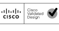
Master rack (single rack) is a standalone solution. The multiple rack solution consists of a master rack and one or more expansion racks. In a single UCS management domain, up to 9 expansion racks are supported. Deployments requiring more than 10 racks can be implemented by interconnecting multiple domains using Cisco Nexus 6000/7000 series switches and managed by UCS Central. Figure 1 shows the FlexPod Select for Hadoop master rack model.
Master Rack
The master rack consists of the following:
•
•
•
•
•
•
•
•
•
Figure 1 Cisco Master Rack
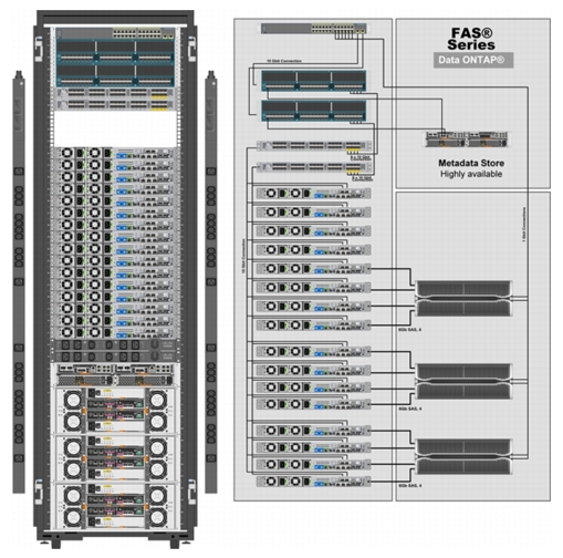
Expansion Rack
Figure 2 shows the FlexPod Select for Hadoop expansion rack model. The expansion rack consists of the following:
•
•
•
•
•
•
Figure 2 Cisco Expansion Rack
Rack and PDU Configuration
The rack configurations of the master rack and expansion rack are shown in Table 2 based on a Cisco 42U rack.
The configuration consists of two vertical PDUs and two horizontal PDUs. The Cisco UCS 6296UP Fabric Interconnects, NetApp E5460s and NetApp FAS2220 are connected to each of the horizontal PDUs. The Cisco Nexus 2232PP Fabric Extenders and Cisco UCS C220M3 Servers are connected to each of the vertical PDUs for redundancy; thereby, ensuring availability during power source failure.
Note
Fabric Configuration
The master rack configuration consists of two Cisco UCS 6296UP Fabric Interconnects and two Cisco Nexus Fabric Extender 2232PP forming two fabrics, Fabric A and Fabric B topology. The Cisco UCS C220M3 Servers 1 to 16 are connected to Fabric A and Fabric B using 10Gb Ethernet connectivity through Cisco Nexus 2232PP Fabric Extenders, with eight uplinks.
The configuration details of the master rack and expansion racks are shown in Figure 1 and Figure 2 respectively.
Storage Configuration
NetApp E5460 belong to the NetApp E5400 modular data storage system family that support big-bandwidth datasets requiring high sequential throughput. The NetApp E5460s are configured with dual SAS controllers and 60 3TB 7.2K RPM SAS disk drives.
For more information, see:
http://www.netapp.com/us/products/storage-systems/e5400/index.aspx
NetApp FAS2200 offers powerful, affordable, flexible data storage for midsized businesses and distributed enterprises. The NetApp FAS2220 has 6 drives (600GB, 10K rpm, SAS) and 4 x 1GbE ports and 2 x 10GbE ports.
For more information, see:
http://www.netapp.com/us/products/storage-systems/fas2200/
Server Configuration and Cabling
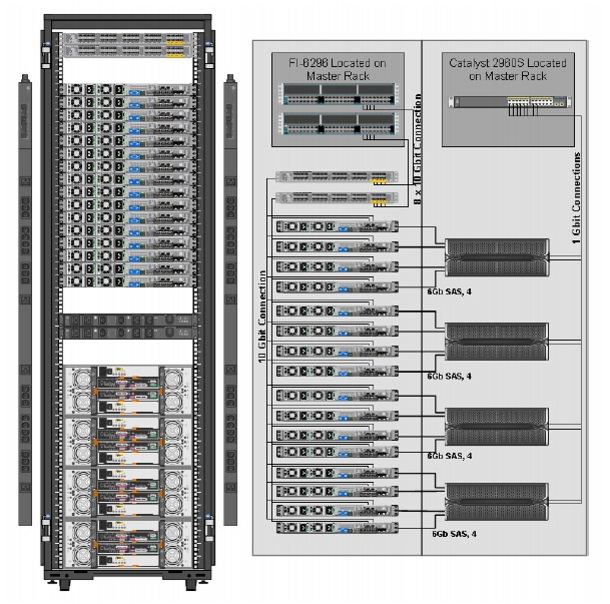
Figure 3 illustrates the physical connectivity of Cisco UCS 6296UP Fabric Interconnects, Cisco Nexus 2232PP Fabric Extenders, and Cisco UCS C220M3 Servers.
Figure 3 Cisco Hardware Connectivity
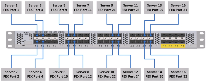
Figure 4 shows the ports of the Cisco Nexus 2232PP Fabric Extender connecting the Cisco UCS C220M3 Servers. Sixteen Cisco UCS C220M3 Servers are used in the master and expansion rack configurations offered by the FlexPod Select for Hadoop.
Figure 4 Connectivity Diagram of Cisco Nexus 2232PP FEX and Cisco UCS C220M3 Servers
Note
For more information on configuring single-wire management, see:
http://www.cisco.com/en/US/docs/unified_computing/ucs/c-series_integration/ucsm2.1/b_UCSM2-1_C-Integration_chapter_010.html
For more information on physical connectivity illustrations and cluster setup, see:
http://www.cisco.com/en/US/docs/unified_computing/ucs/c-series_integration/ucsm2.1/b_UCSM2-1_C-Integration_chapter_010.html#reference_FE5B914256CB4C47B30287D2F9CE3597
Software Requirements
For this deployment we have used Cloudera Distribution for Apache Hadoop (CDH), which is an open source distribution with the World's leading Apache Hadoop solution.
CDH
Cloudera software for Cloudera Distribution for Apache Hadoop is v4.x (CDH4). For more information on Cloudera, see:
RHEL
The operating system supported is Red Hat Enterprise Linux Server 6.2. For more information on the Linux support, see:
Software Versions
Table 3 provides the software version details of all the software requirements for this model.
Fabric Configuration
This section provides details for configuring a fully redundant, highly available configuration for a FlexPod Select for Hadoop. Follow these steps to configure Cisco 6296UP Fabric Interconnect.
1.
2.
3.
4.
5.
6.
7.
8.
9.
10.
Performing an Initial Setup of Cisco UCS 6296UP Fabric Interconnects
Follow these steps for initial setup of the Cisco UCS 6296 Fabric Interconnects:
Cisco UCS 6296 FI A
1.
2.
3.
4.
5.
6.
7.
8.
9.
10.
11.
12.
13.
14.
15.
16.
17.
18.
19.
20.
Cisco UCS 6296UP FI B
1.
2.
3.
4.
5.
6.
7.
For more information on configuring Cisco UCS 6200 Series Fabric Interconnect, see:
Logging into Cisco UCS Manager
Follow these steps to log into Cisco UCS Manager:
1.
2.
3.
4.
Upgrade Cisco UCS Manager Software to Version 2.1(1e)
This document assumes the use of UCS 2.1(1e). For more information on upgrading the software version to Cisco UCS 2.0 release, see:
This link provides you information on upgrading Cisco UCS Manager software and Cisco UCS 6296 Fabric Interconnect software to version 2.1(1e).
Note
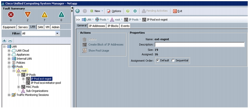
Adding a Block of IP Addresses for KVM Console
Follow these steps to create a block of KVM IP addresses for server access in the Cisco UCS Manager GUI:
1.
2.
Figure 5 Management IP Pool in Cisco UCS Manager
3.
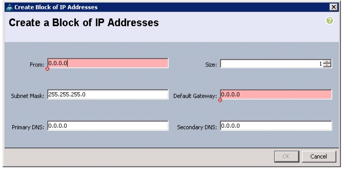
4.
Figure 6 Creating a Block of IP Addresses
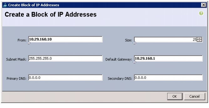
5.
Figure 7 Entering the Block of IP Addresses
6.
7.
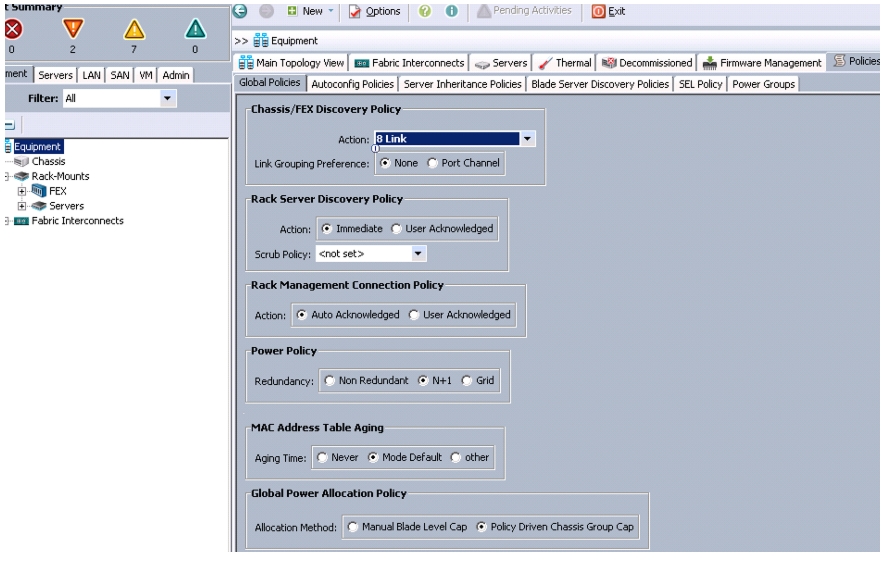
Editing the Chassis Discovery Policy
Setting the discovery policy now will simplify the addition of Cisco UCS B-Series Chassis in the future and additional fabric extenders for further C-Series connectivity.
To modify the chassis discovery policy, follow these steps:
1.
2.
3.
Figure 8 Editing the Chassis Discovery Policy
4.
5.
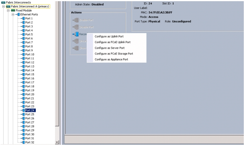
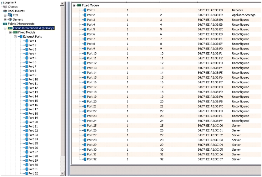
Enabling Server and Uplink Ports
To enable the server ports and uplink ports, follow these steps:
1.
2.
3.
4.
Figure 9 Enabling Server Ports
5.
6.
7.
8.
9.
10.
11.
12.
13.
14.
Figure 10 Window Showing Server Ports and Uplink Ports
Creating Pools for Service Profile Template
Creating an Organization
Organizations are used as a means to organize and restrict access to various groups within the IT organization, thereby enabling multi-tenancy of the compute resources. This document does not assume the use of Organizations; however the necessary steps are provided for future reference.
Follow these steps to configure an organization in the Cisco UCS Manager GUI:
1.
2.
3.
4.
5.
6.
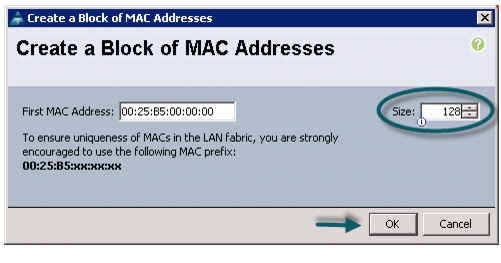
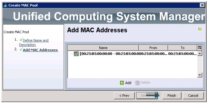
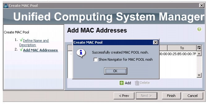
Creating MAC Address Pools
Follow these steps to configure the necessary MAC address pools in the Cisco UCS Manager GUI:
1.
2.
3.
4.
5.
6.
7.
8.
9.
10.
Figure 11 Specifying the First MAC Address and Size
Figure 12 Range of MAC Addresses
Figure 13 Created MAC Pool
11.
12.
13.
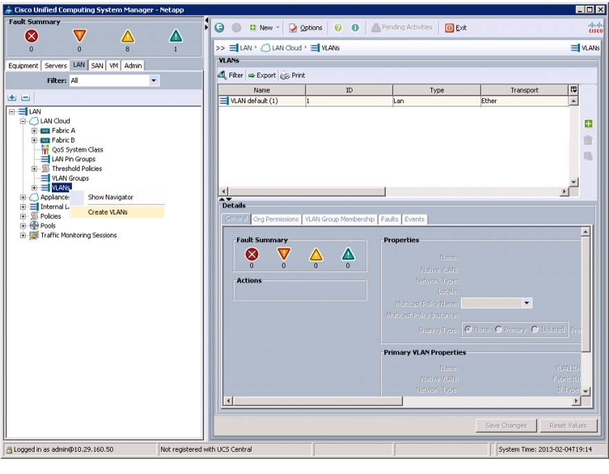
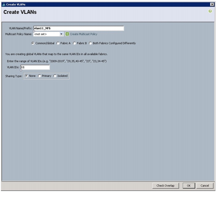
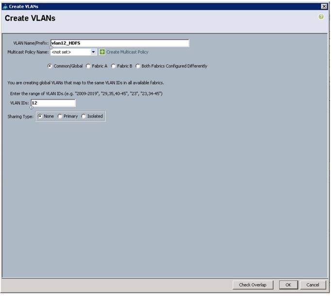
Configuring VLANs
VLANs are configured as shown in Table 4.
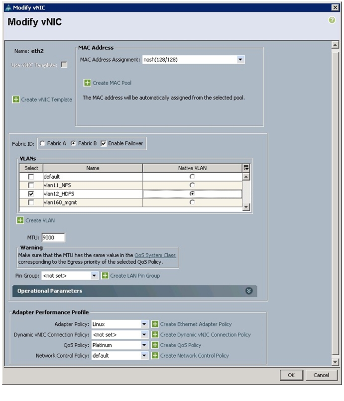
For this deployment we are using eth0 (vlan160_mgmt) for management packets, eth1 (vlan11_NFS) for NFS data traffic and eth2 (vlan12_HDFS) for HDFS data traffic.
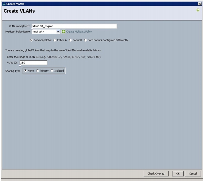
Follow these steps to configure VLANs in the Cisco UCS Manager GUI:
1.
2.
3.
4.
Figure 14 Creating VLANs
5.
6.
7.
Figure 15 Creating VLAN for Fabric A
8.
9.
10.
11.
12.
13.
14.
15.
16.
Figure 16 Creating VLAN for Fabric B
17.
18.
19.
20.
21.
22.
23.
24.
25.
Figure 17 Creating Global HDFS VLAN
26.
Note
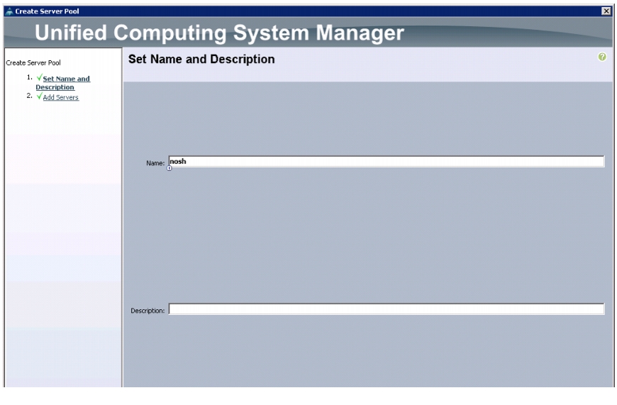
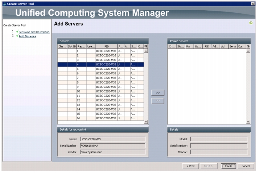
Creating Server Pool
A server pool contains a set of servers. These servers typically share the same characteristics. Those characteristics can be their location in the chassis, or an attribute such as server type, amount of memory, local storage, type of CPU, or local drive configuration. You can manually assign a server to a server pool, or use server pool policies and server pool policy qualifications to automate the assignment.
Follow these steps to configure the server pool in the Cisco UCS Manager GUI:
1.
2.
3.
4.
5.
6.
Figure 18 Creating Server Pool
7.
8.
Figure 19 Adding Server Pool
9.
10.
Creating Policies for Service Profile Template
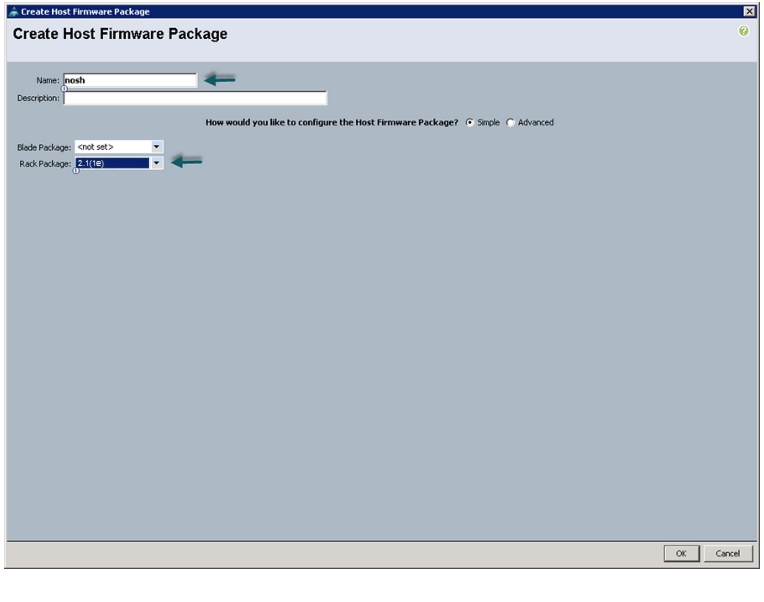
Creating Host Firmware Package Policy
Firmware management policies allow the administrator to select the corresponding packages for a given server configuration. These often include adapter, BIOS, board controller, FC adapters, HBA option ROM, and storage controller properties.
Follow these steps create a firmware management policy for a given server configuration in the Cisco UCS Manager GUI:
1.
2.
3.
4.
5.
6.
7.
Figure 20 Creating Host Firmware Package
8.
9.
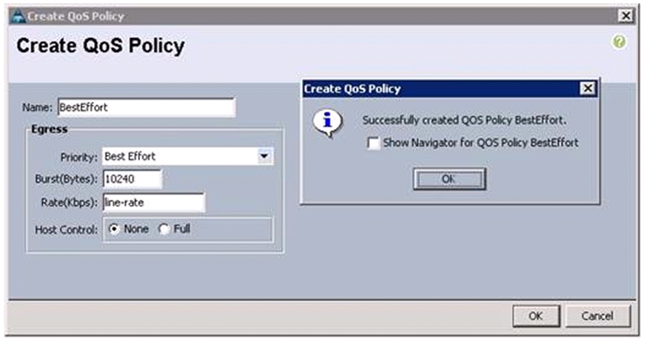
Creating QoS Policies
Follow these steps to create QoS policy for a given server configuration in the Cisco UCS Manager GUI:
BestEffort Policy
1.
2.
3.
4.
5.
6.
7.
8.
9.
Figure 21 Creating QoS Policy - BestEffort
10.
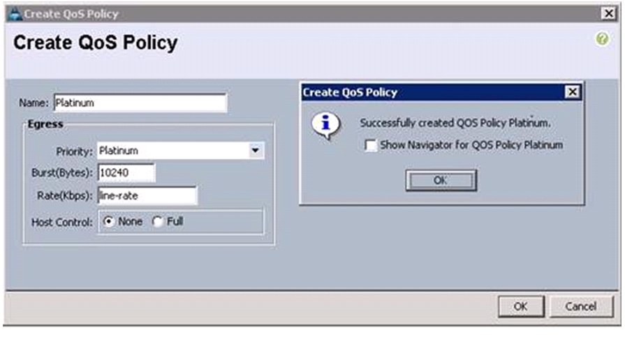
Platinum Policy
1.
2.
3.
4.
5.
6.
7.
8.
9.
Figure 22 Creating QoS Policy - Platinum
10.
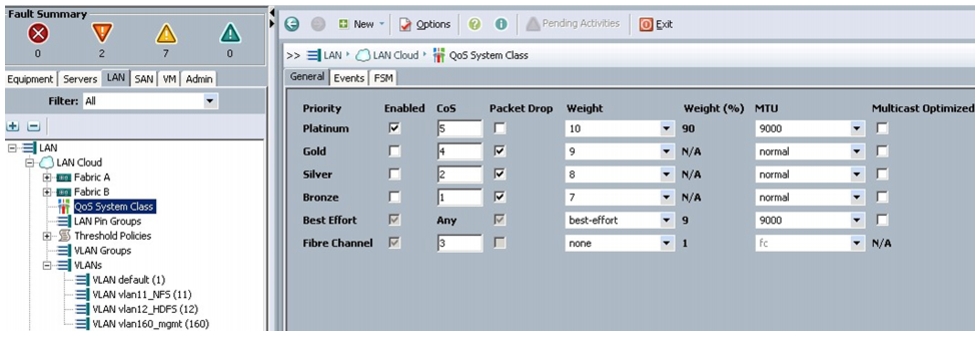
Setting Jumbo Frames
These steps provide details for setting Jumbo frames and enabling the quality of service in the Cisco UCS Fabric:
1.
2.
3.
4.
5.
6.
Figure 23 Setting Jumbo Frame in Cisco UCS Fabric
7.
8.
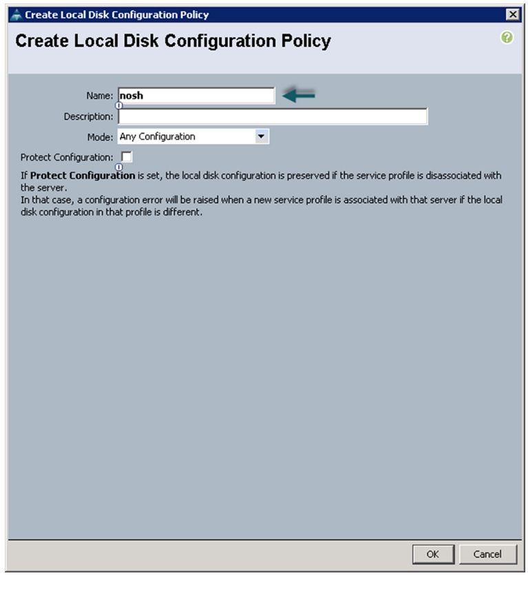
Create a Local Disk Configuration Policy
Follow these steps to create local disk configuration in the Cisco UCS Manager GUI:
1.
2.
3.
4.
5.
6.
Figure 24 Configuring Local Disk Policy
7.
8.
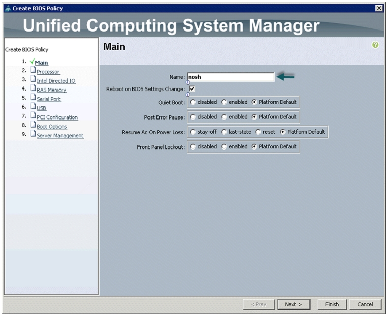
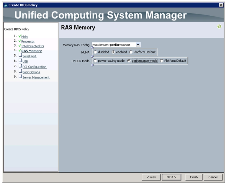
Create a Server BIOS Policy
The BIOS policy feature in Cisco UCS automates the BIOS configuration process.
The traditional method of setting the BIOS is manual and often error-prone. By creating a BIOS policy and assigning the policy to a server or group of servers, you can have the transparency in BIOS settings and configuration.
Follow these steps to create a server BIOS policy in the Cisco UCS Manager GUI:
1.
2.
3.
4.
5.
6.
Figure 25 Creating BIOS Policy
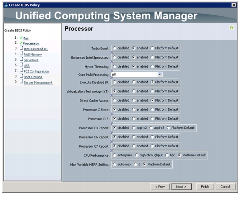
Figure 26 Processor Settings
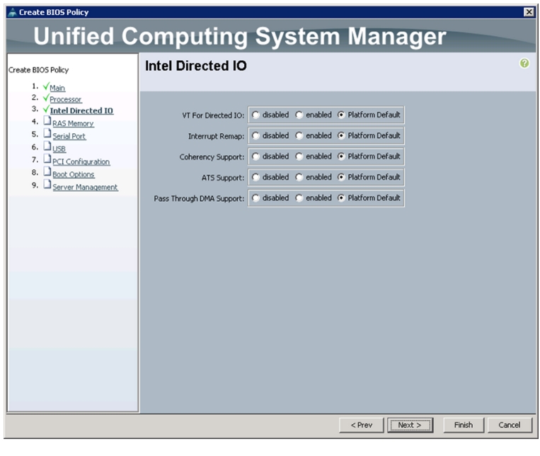
Figure 27 Intel Direct IO Settings
Figure 28 Memory Settings
7.
8.
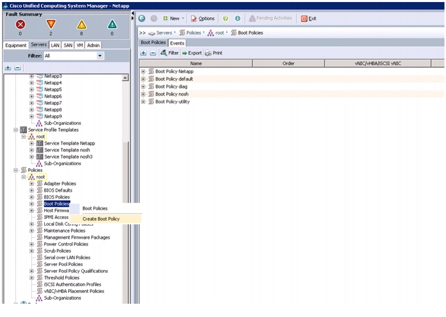
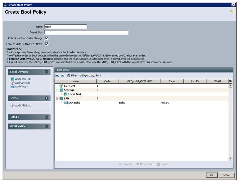
Creating Boot Policies
Follow these steps to create boot policies within the Cisco UCS Manager GUI:
1.
2.
3.
4.
Figure 29 Creating Boot Policy
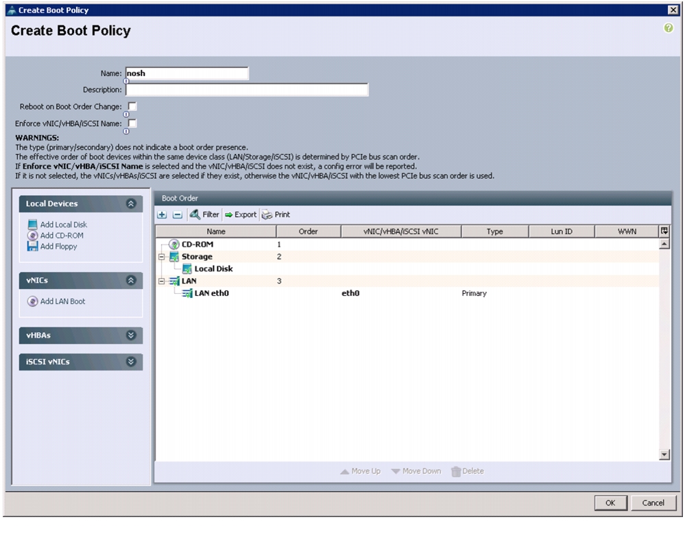
5.
6.
7.
8.
9.
10.
Figure 30 Creating Boot Order
11.
12.
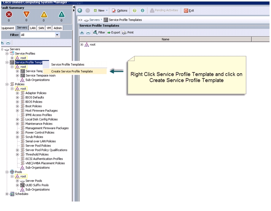
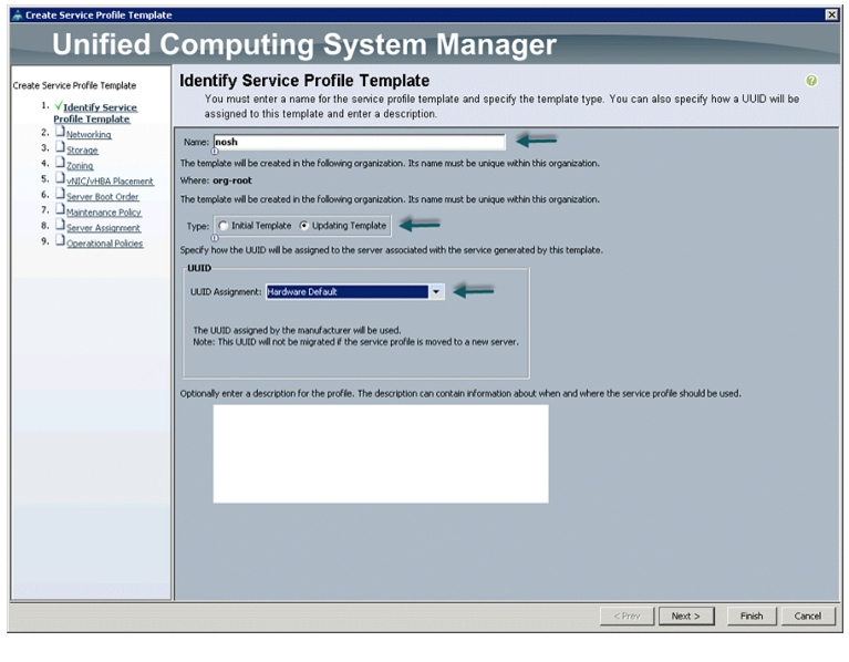
Creating Service Profile Template
To create a service profile template, follow these steps:
1.
2.
3.
4.
Figure 31 Creating Service Profile Template
5.
The following steps provide the detailed configuration procedure used to create a service profile template:
a.
b.
Figure 32 Identifying Service Profile Template
c.
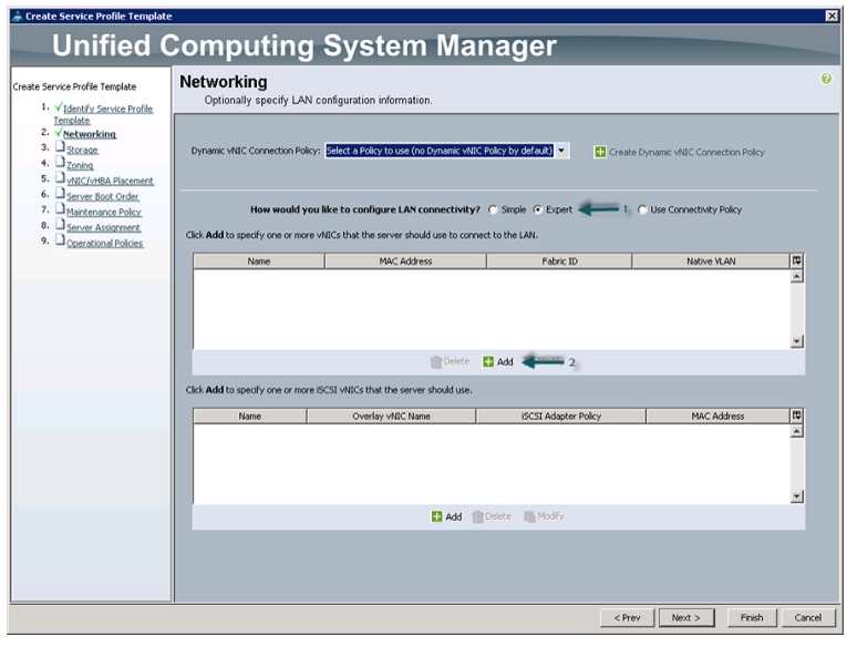
Configuring Network Settings for the Template
In the Networking window, follow these steps to create vNICs:
1.
2.
3.
Figure 33 Adding vNICs
4.
5.
6.
7.
8.
9.
10.
11.
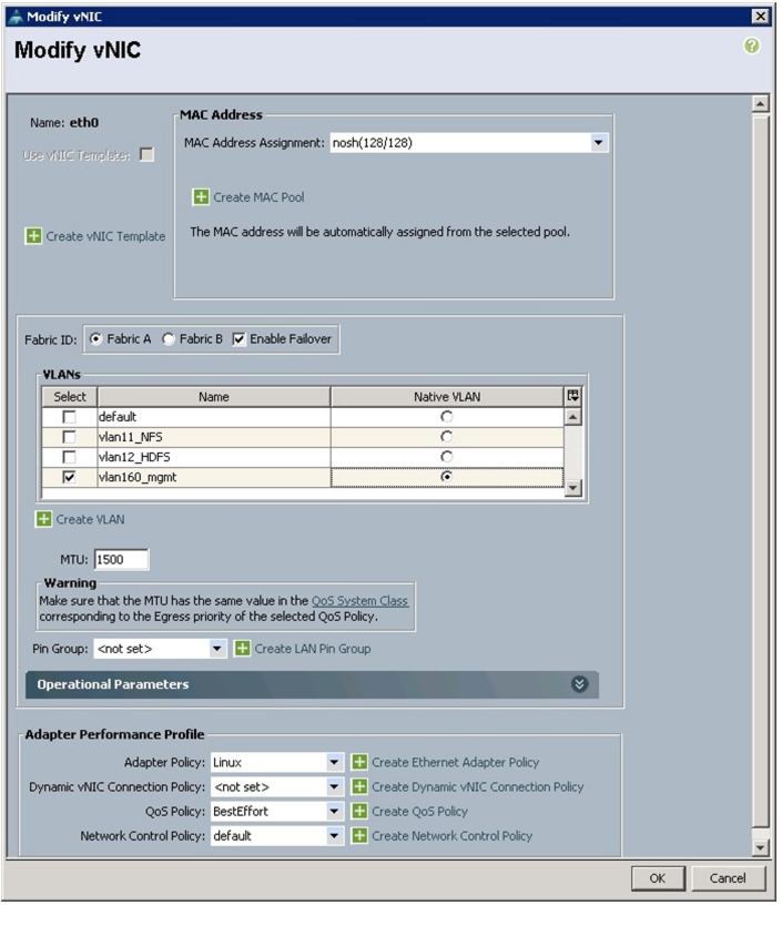
12.
Figure 34 Creating Management vNIC
13.
14.
15.
16.
17.
18.
19.
20.
21.
22.
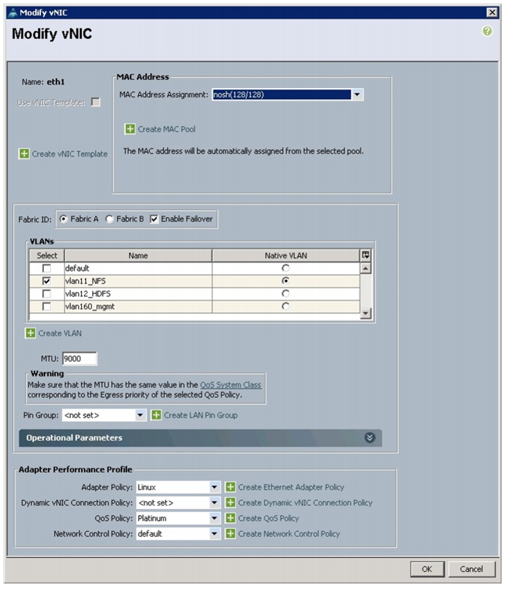
23.
Figure 35 Creating NFS vNIC
24.
25.
26.
27.
28.
29.
30.
31.
32.
33.
34.
Figure 36 Creating HDFS vNIC
35.
36.
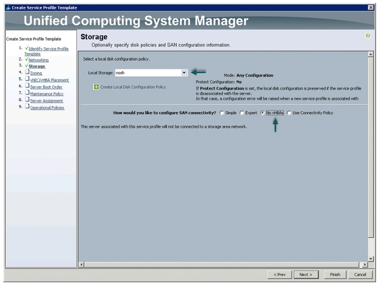
Configuring Storage Policy for the Template
In the Storage window, follow these steps to configure storage:
1.
2.
Figure 37 Storage Settings
3.
4.
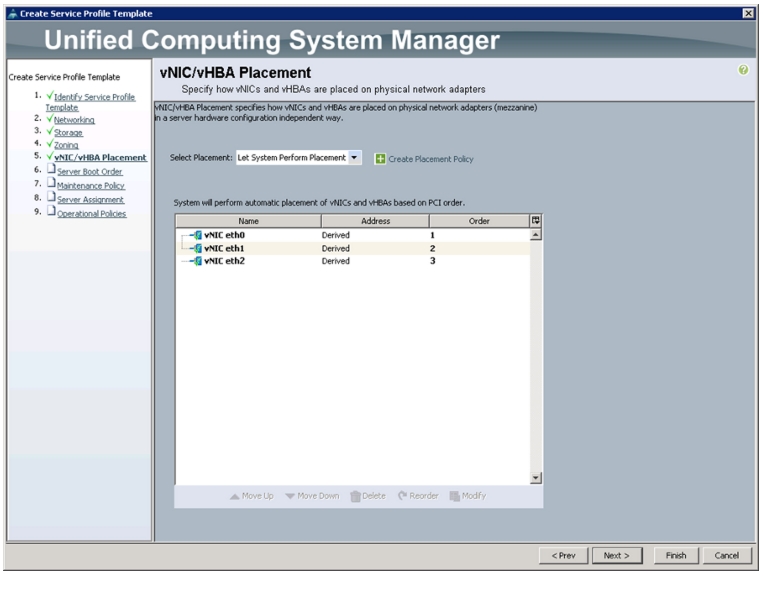
Configuring vNIC/vHBA Placement for the Template
In the vNIC/vHBA Placement Section, follow these steps to configure placement policy:
1.
2.
–
–
–
3.
Figure 38 Creating vNIC and vHBA Policy
4.
Configuring Server Boot Order for the Template
In the Server Boot Order Section, follow these steps to set the boot order for servers:
1.
2.
3.
4.
Figure 39 Creating Boot Policy
5.
6.
Configuring Maintenance Policy for the Template
In the Maintenance Policy window, follow these steps to apply maintenance policy:
1.
2.
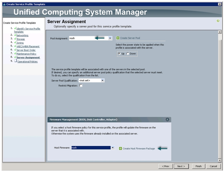
Configuring Server Assignment for the Template
In the Server Assignment window, follow these steps to assign servers to the pool:
1.
2.
3.
Figure 40 Assigning Sever Pool for Service Profile Template
4.
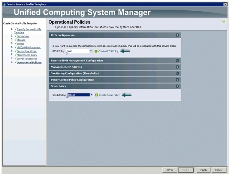
Configuring Operational Policies for the Template
In the Operational Policies window, follow these steps:
1.
Figure 41 Creating Operational Policies
2.
3.
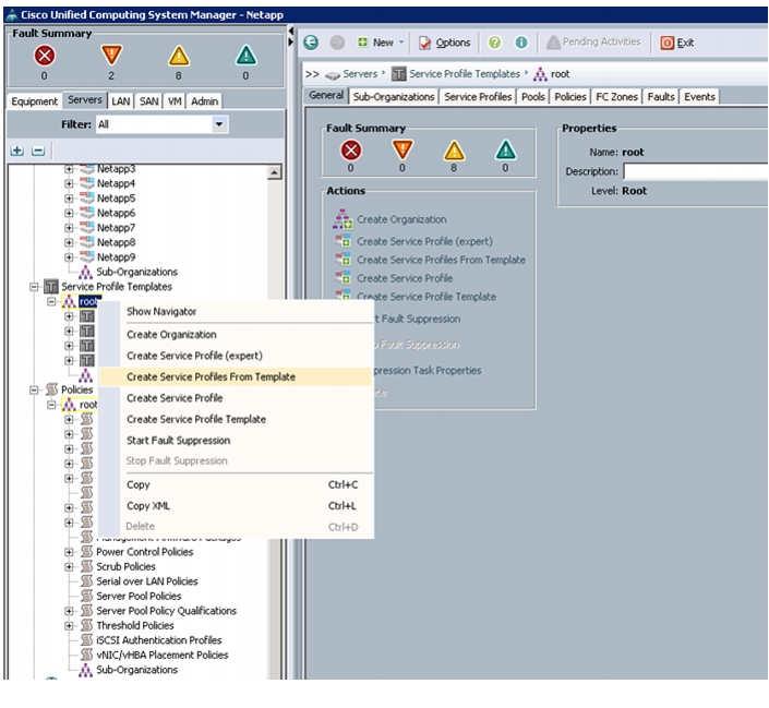
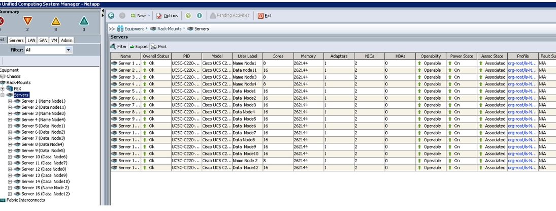
Select the Servers tab in the left pane in the UCSM GUI.
1.
2.
3.
Figure 42 Creating Service Profile
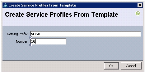
4.
Figure 43 Creating Service Profile from Template
5.
6.
7.
8.
Figure 44 UCS Manager Showing Sixteen Nodes
Cisco UCS 6296UP FI Configuration for NetApp FAS 2220
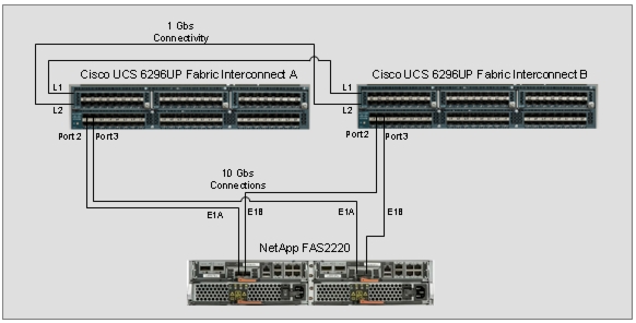
The Cisco UCS 6296UP Fabric Interconnects are deployed in pairs with L1 to L1 and L2 to L2 connectivity for redundancy. NetApp FAS 2220 has one storage controllers. FAS controller port E1A is connected to FI A Port 2 as the Appliance port and E1B is connected to FI B Port 2 as the Appliance port with 10Gbs connectivity as shown in Figure 45.
Figure 45 Cisco UCS 6296UP FIs and NetApp FAS 2220 Connectivity
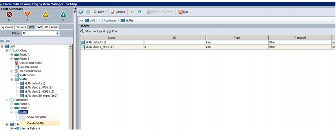
Configuring VLAN for Appliance Port
Follow these steps to configure VLAN appliance cloud:
1.
2.
3.
4.
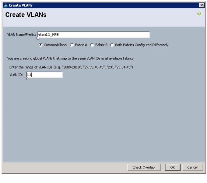
Figure 46 Creating VLANs for Appliance Cloud
5.
6.
7.
Figure 47 Creating VLAN for Fabric A
8.
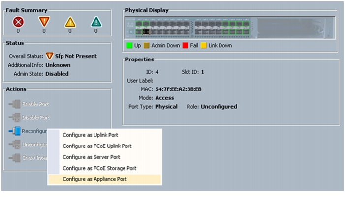
Configure Appliance Port
Follow these steps to configure appliance ports:
1.
2.
3.
4.
Figure 48 Configuring Fabric A Appliance Port
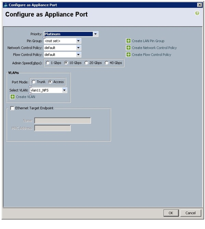
5.
6.
7.
8.
9.
10.
11.
12.
Figure 49 Configuring Appliance Port
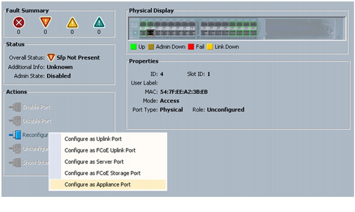
13.
14.
15.
16.
17.
Figure 50 Configuring Fabric B Appliance Port
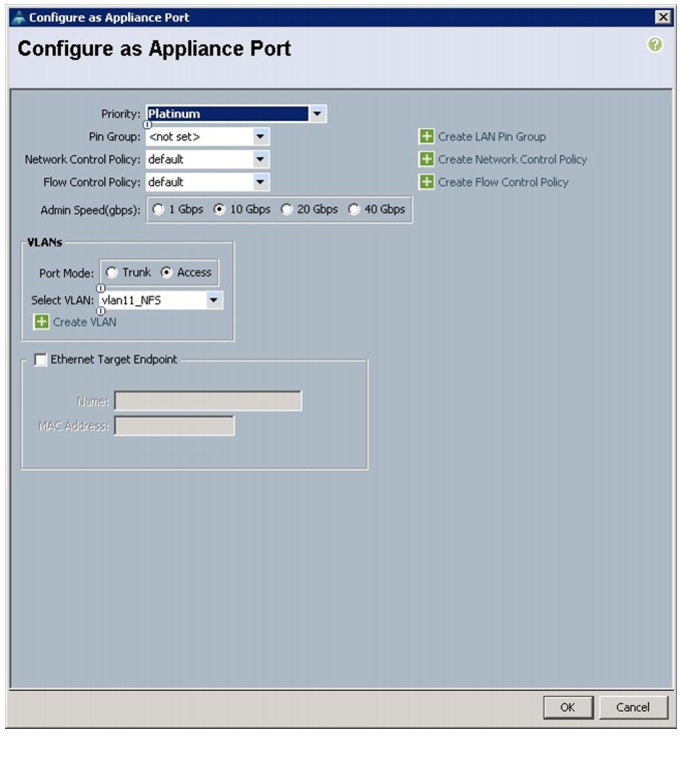
18.
19.
20.
21.
22.
23.
24.
25.
Figure 51 Configuring Appliance Port
26.
27.
Server and Software Configuration
Service profile template creation is explained in "Fabric Configuration" section.
The following sections provide a detailed configuration procedure of the Cisco UCS C-Series Servers. These steps should be followed precisely because a failure to do so could result in an improper configuration.
Performing Initial Setup of C-Series Servers
These steps provide details for initial setup of the Cisco UCS C-Series Servers. It is important to get the systems to a known state with the appropriate firmware package.
Logging into the Cisco UCS 6200 Fabric Interconnects
To log into the Cisco UCS Manager application through Cisco UCS 6200 Series Fabric Interconnect, follow these steps:
1.
2.
3.
4.
Configuring Disk Drives for OS
There are several ways to configure RAID: using LSI WebBIOS Configuration Utility embedded in the MegaRAID BIOS, booting DOS and running MegaCLI commands or using third party tools that have MegaCLI integrated. For this deployment, the first disk drive is configured using LSI WebBIOS Configuration Utility. A RAID1 volume of two disk drives is configured for the operating system:
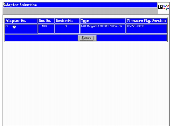
1.
–
–
–
2.
Figure 52 RAID Configuration for LSI MegaRAID SAS Controllers
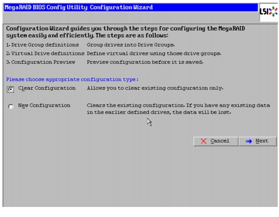
3.
4.
Figure 53 Clearing Existing Configuration
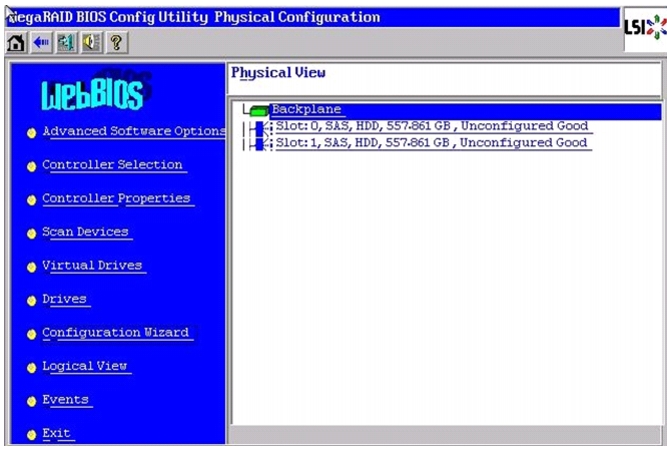
5.
6.
Figure 54 Physical View of Unconfigured Drives
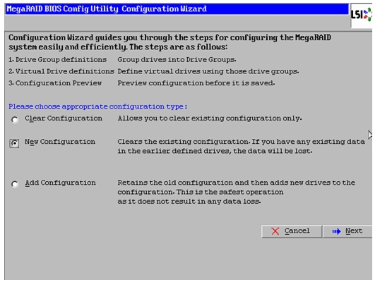
7.
8.
Figure 55 Selecting New Configuration
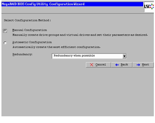
9.
Figure 56 Selecting Manual Configuration
10.
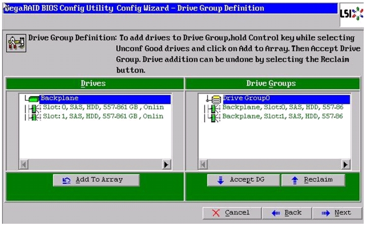
11.
12.
Figure 57 Moving Drives to Drive Groups
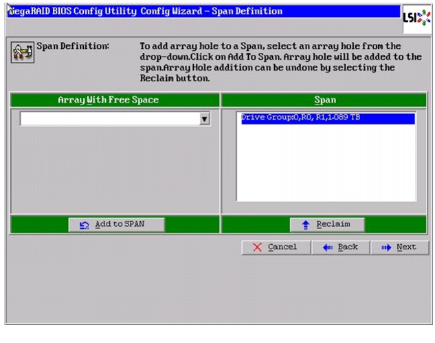
13.
Figure 58 Adding Arrayhole to Span
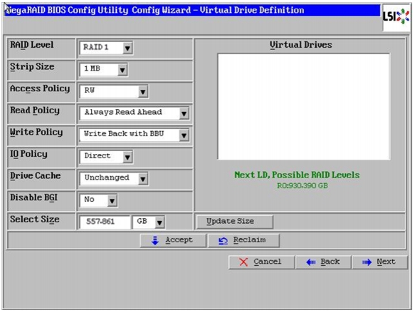
14.
a.
b.
c.
d.
Figure 59 Defining Virtual Drive
e.
f.
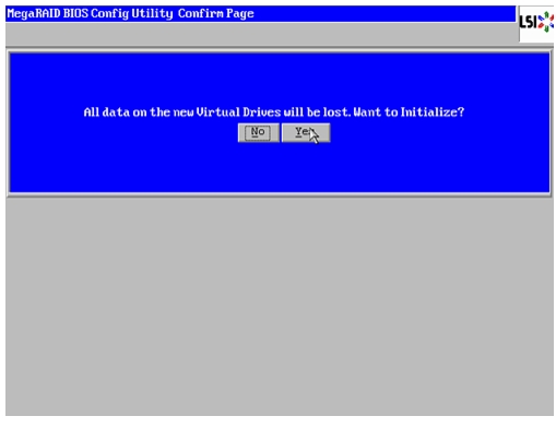
15.
16.
17.
18.
Figure 60 Confirmation to Initialize
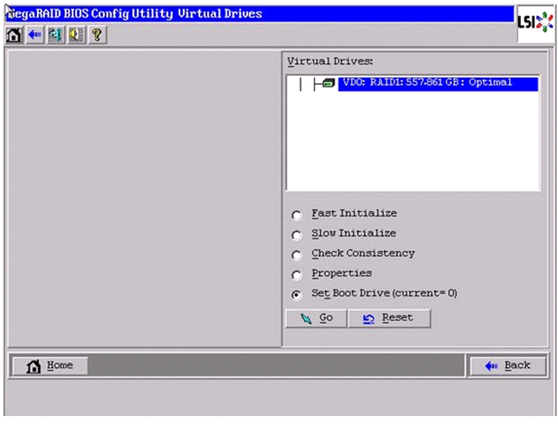
19.
Figure 61 Setting Boot Drive
20.
21.
Installing Red Hat Enterprise Linux Server 6.2 using KVM
One of the options to install RHEL is explained in this section.
You can install Red Hat Enterprise Linux Server 6.2 using the KVM console of Cisco UCS Manager. To open the KVM console, follow these steps:
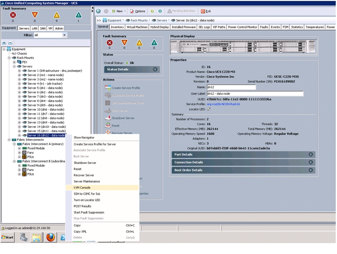
1.
2.
3.
Figure 62 Launching KVM Console
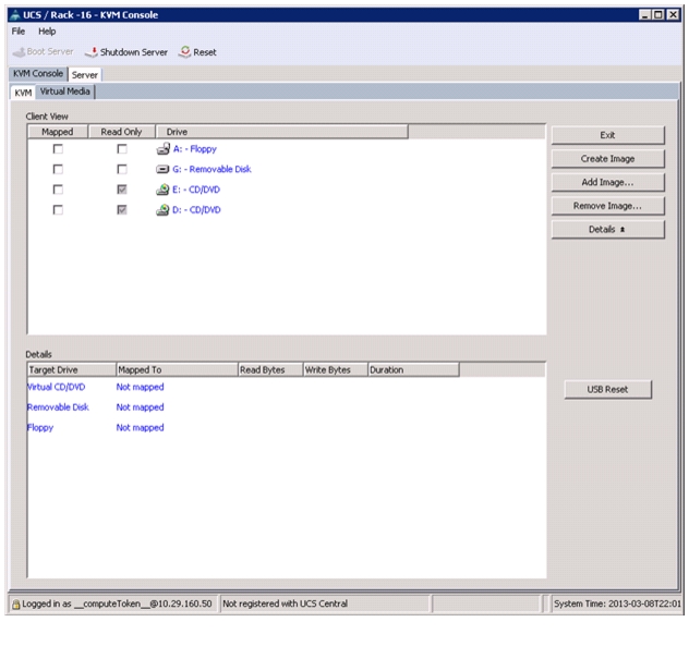
To install Red Hat Linux Server 6.2, follow these steps:
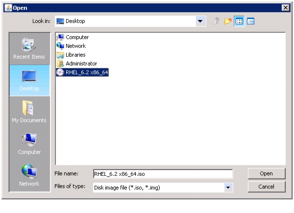
1.
Figure 63 Adding ISO Image
2.
3.
Note
Figure 64 Selecting the Red Hat Enterprise Linux ISO Image
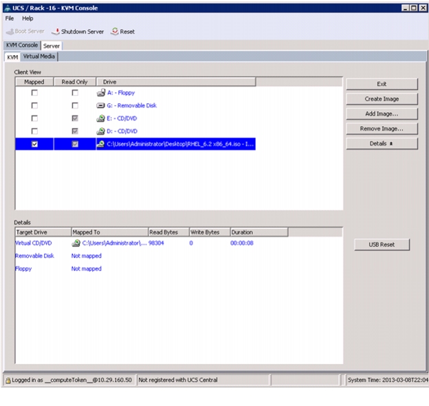
4.
5.
Figure 65 Mapping the ISO Image
6.
7.
8.
9.
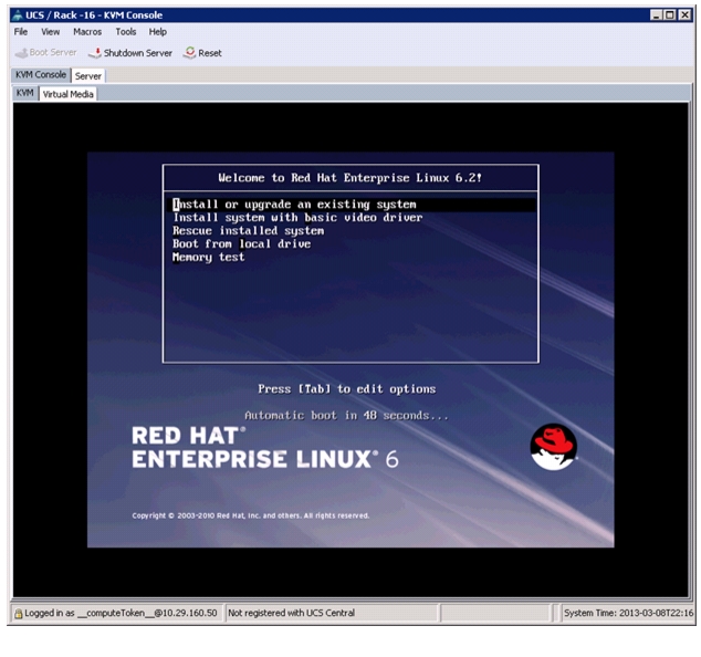
10.
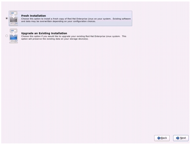
11.
Figure 66 Selecting the RHEL Installation Option
12.
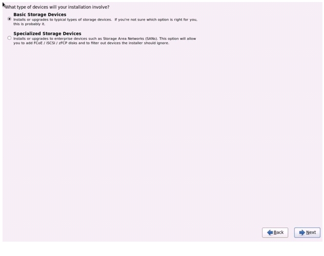
13.
14.
Figure 67 Selecting Storage Device Type
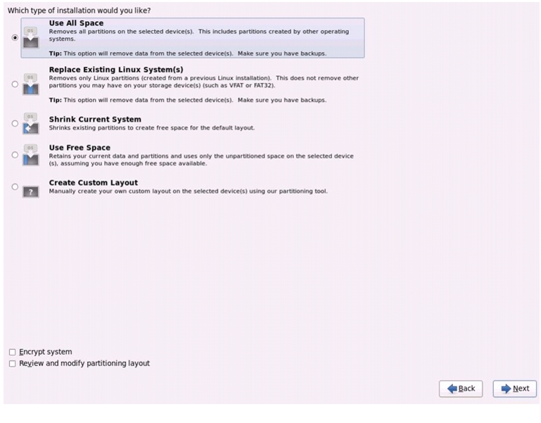
15.
Figure 68 Selecting Installation Type
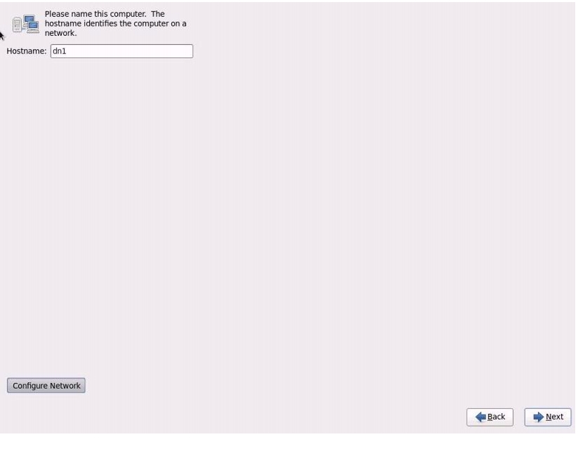
16.
Figure 69 Entering the Host Name
17.
18.
19.
20.
21.
22.
23.
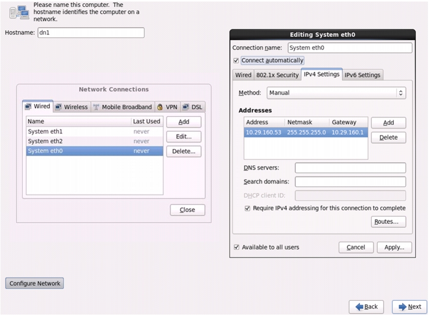
24.
Figure 70 Configuring Network Connections
25.
26.
27.
Figure 71 Selecting RHEL Install Type
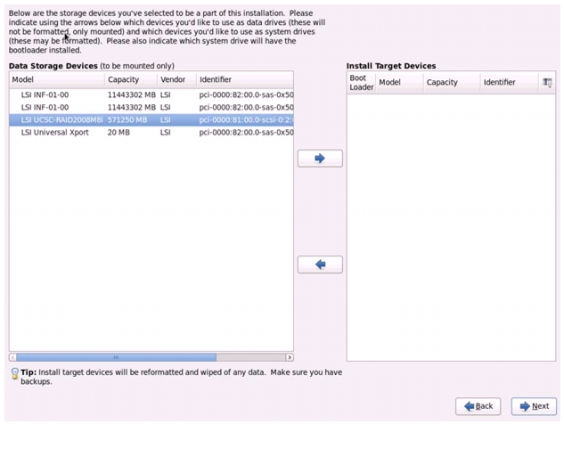
28.
to add the selected boot device to appear in the right pane under Install Target Devices and click Next.
Figure 72 Selecting the Data Storage Device
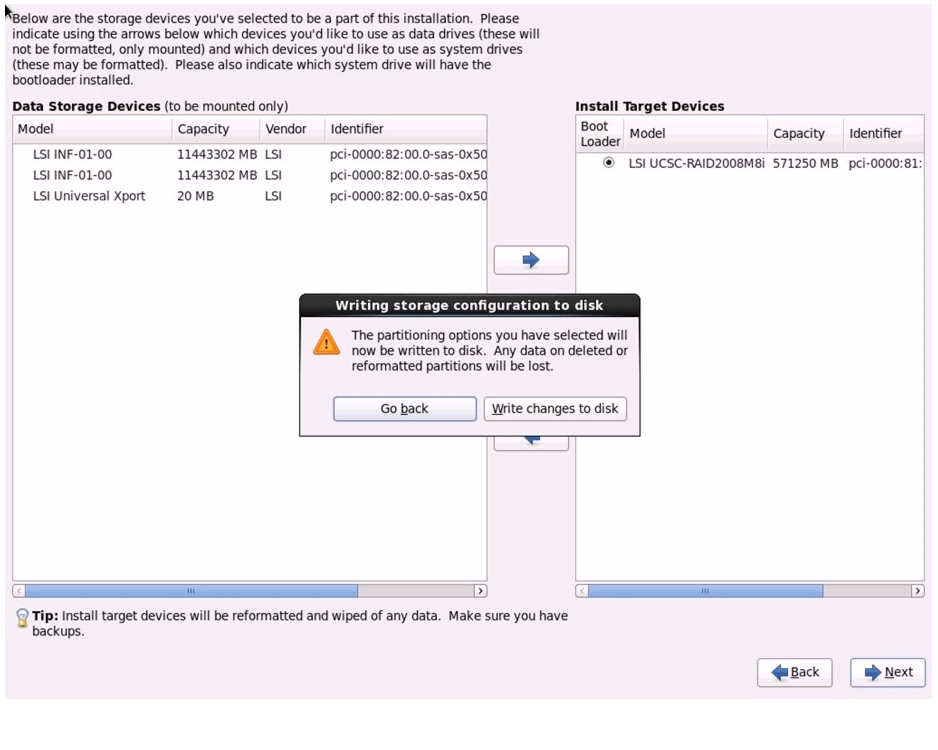
29.
Figure 73 Writing Partitioning Options into the Disk
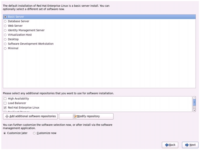
30.
Figure 74 Selecting RHEL Installation Option
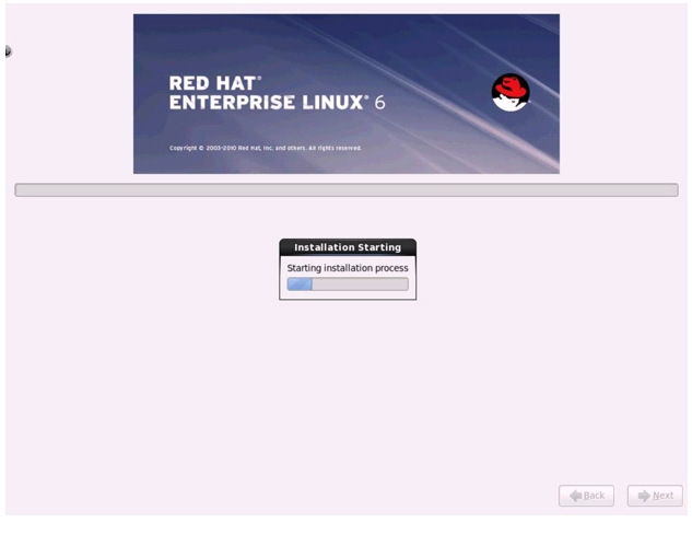
31.
Figure 75 Installation Process in Progress
Post OS Install Configuration
Infrastructure Node
This section describes the steps needed to implement an infrastructure node for the cluster. The infrastructure node may provide some or all of the following services to the namenodes and datanodes in the cluster:
•
•
•
•
•
Note
Installing and Configuring Parallel Shell
Parallel-SSH
Parallel SSH is used to run commands on several hosts at the same time. It takes a file of hostnames and a bunch of common ssh parameters as parameters, executes the given command in parallel on the nodes specified.
The tool can be downloaded from https://code.google.com/p/parallel-ssh/
Fetch and install this tool via the following commands:
cd /tmp/curl https://parallel-ssh.googlecode.com/files/pssh-2.3.1.tar.gz -O -Ltar xzf pssh-2.3.1.tar.gzcd pssh-2.3.1python setup.py installTo make use of pssh, a file containing just only the IP addresses of the nodes in the cluster needs to be created. The following was used for the contents of the /root/pssh.hosts file on all of the nodes and will need to be customized to fit your implementation:
# /root/pssh.hosts - cluster node IPs or names10.29.160.5310.29.160.5410.29.160.5510.29.160.5610.29.160.5710.29.160.5810.29.160.5910.29.160.6010.29.160.6110.29.160.6210.29.160.6310.29.160.6410.29.160.6510.29.160.6610.29.160.6710.29.160.68This file is used with pssh by specifying the -h option on the command line. For example, the following command will execute the hostname command on all of the nodes listed in the /root/pssh.hosts file:
pssh -h /root/pssh.hosts -A hostnameFor information on the -A option and other pssh options, use one or both of the following commands:
pssh -helpman psshCreate Local Redhat Repo
If your infrastructure node and your cluster nodes have Internet access, you may be able to skip this section.
To create a repository using RHEL DVD or ISO on the infrastructure node (in this deployment 10.29.160.53 is as an infrastructure node), create a directory with all the required RPMs, run the createrepo command and then publish the resulting repository.
1.
mkdir -p /var/www/html/Cloudera/mkdir -p /var/www/html/JDK/mkdir -p /var/www/html/RHEL/6.2/2.
mount /rhel-server-6.2-x86_64-dvd.iso/mnt -t iso9660 -o ro,loop=/dev/loop13.
cd /mnt/;tar -c -p -b 128 -f - .cd /var/www/html/RHEL/6.2/;tar -x -p -b 128 -f - .diff -r /mnt/ /var/www/html/RHEL/6.2/4.
cat > /var/www/html/RHEL/6.2/rhel62copy.repo[rhel6.2]name=Red Hat Enterprise Linux 6.2baseurl=file:///var/www/html/RHEL/6.2/gpgcheck=0enabled=1
Note
5.
pscp -h /root/pssh.hosts \/var/www/html/RHEL/6.2/rhel62copy.repo /etc/yum.repos.d/6.
Install the createrepo package. Use it to regenerate the repository database(s) for the local copy of the RHEL DVD contents. Then purge the yum caches.
yum -y install createrepocd /var/www/html/RHEL/6.2/createrepo .yum clean all7.
pssh -h /root/allnodes "yum clean all"Install Required Packages
This section assumes that only the default basic server install has been done.
Table 5 provides a list of packages that are required.
Table 5 Required list of packages
xfsprogs
Utilities for managing XFS filesystem
jdk
Java SE Development Kit6, Update 39(JDK 6u39) or more recent
Utilities
dnsmasq, httpd, lynx
Note
Create the following script install_packages.sh to install required packages:
Script install_packages.sh
yum -y install dnsmasq httpd lynx# get and install xfsprogs from local repo on Infrastructure nodecd /tmp/curl http://10.29.160.53/RHEL/6.2/Packages/xfsprogs-3.1.1-6.el6.x86_64.rpm -O -Lrpm -i /tmp/xfsprogs-3.1.1-6.el6.x86_64.rpmCopy script disable_services.sh to all nodes and run the script on all nodes:
pscp -h /root/pssh.hosts /root/install_packages.sh /root/pssh -h /root/pssh.hosts "/root/install_packages.sh"Disable SELinux
Execute the following commands to disable SELinux on all the nodes:
pssh -h /root/pssh.hosts "setenforce 0"pssh -h /root/pssh.hosts "sed -i -e 's/=enforcing/=disabled/g;'\ /etc/selinux/config"Disable Unwanted ServicesExecute the following commands as a script to disable and turn off unwanted services on all nodes:
Script disable_services.sh
$cat disable_services.sh# disble/shutdown things we do not needfor X in bluetooth certmonger cgconfigd cgred cpuspeed cups dnsmasq \ebtables fcoe fcoe-target ip6tables iptables iscsi iscsid ksm ksmtuned \libvirtd-guests libvirtd postfix psacct qpidd rhnsd rhsmcertd \sendmail smartd virt-who vsftpd winbind wpa_supplicant ypbind NetworkManagerdo/sbin/service $X stop/sbin/chkconfig $X offdoneCopy script disable_services.sh to all nodes and run the script on all nodes:
pscp -h /root/pssh.hosts /root/disable_servicesh.h /root/pssh -h /root/pssh.hosts "/root/disable_services.sh"Enable and start the httpd service
Before starting the httpd service, you may need to edit the server configuration file (/etc/httpd/conf/httpd.conf) to change one or more of the following settings:
•
•
•
•
Ensure httpd is able to read the repofiles
chcon -R -t httpd_sys_content_t /var/www/html/RHEL/6.2/Perform the following commands to enable and start the httpd service:
chkconfig httpd onservice httpd startJDK Installation
Download Java SE 6 Development Kit (JDK)
Using a web browser, click on the following link:
http://www.oracle.com/technetwork/java/index.html
and download the latest Java™ SE 6 Development Kit (JDK™6).
Once the JDK6 package has been downloaded, place it in the /var/www/html/JDK/ directory.
Install JDK6 on All Node
Create the following script install_jdk.sh to install JDK:
Script install_jdk.sh
# Copy and install JDKcd /tmp/curl http://10.29.160.53/JDK/jdk-6u41-linux-x64.bin -O -Lsh ./jdk-6u41-linux-x64.bin -noregisterCopy script disable_services.sh to all nodes and run the script on all nodes:
pscp -h /root/pssh.hosts /root/install_jdk.sh /root/pssh -h /root/pssh.hosts "/root/install_jdk.sh"Local Cloudera Software Repos
This section deals with making local mirrors of the Cloudera repositories for:
•
•
•
These instructions deal with mirroring the latest releases only.
Note
Cloudera Manager Repo
The following commands will mirror the latest release of Cloudera Manager, version 4.x:
cd /var/www/html/Cloudera/curl http://archive.cloudera.com/cm4/redhat/6/x86_64/cm/cloudera-manager.repo -O -Lreposync --config=./cloudera-manager.repo --repoid=cloudera-managercreaterepo --baseurl http://10.29.160.53/Cloudera/cloudera-manager/ \${PWD}/cloudera-managerCloudera Manager Installer
The following commands will mirror the latest release of the Cloudera Manager Installer utility:
cd /var/www/html/Cloudera/cloudera-manager/curl http://archive.cloudera.com/cm4/installer/latest/cloudera-manager-installer.bin -O -Lchmod uog+rx cloudera-manager-installer.binCloudera Enterprise Core Repo
The following commands will mirror the latest release of Cloudera Enterprise Core, version 4.x:
cd /var/www/html/Cloudera/curl http://archive.cloudera.com/cdh4/redhat/6/x86_64/cdh/cloudera-cdh4.repo -O -Lreposync --config=./cloudera-cdh4.repo --repoid=cloudera-cdh4createrepo --baseurl http://10.29.160.53/Cloudera/cloudera-cdh4 ${PWD}/cloudera-cdh4Next, a .repo file must be created. The following commands will create a .repo file:
cat > cloudera-manager/cloudera-manager.repo[cloudera-manager]name=Cloudera Managerbaseurl=http://10.29.160.53/Cloudera/cloudera-manager/gpgcheck=0enabled=1priority=1chmod uog-wx cloudera-manager/cloudera-manager.repocp -pv cloudera-manager/cloudera-manager.repo /etc/yum.repos.d/Cloudera Impala Repo
The following commands will mirror the latest release of Cloudera Impala - beta, version 0.x:
cd /var/www/html/Cloudera/curl http://beta.cloudera.com/impala/redhat/6/x86_64/impala/cloudera-impala.repo -O -Lreposync --config=./cloudera-impala.repo --repoid=cloudera-impalacreaterepo --baseurl http://10.29.160.53/Cloudera/cloudera-impala \${PWD}/cloudera-impalaAt this point, the Cloudera repositories for CDH4, CM, Impala and the CM Installer should be mirrored locally on the infrastructure node.
For more information, refer to Cloudera Installation Guide.
Services to Configure On Infrastructure Node
These are some of the other services that you may want to configure on the infrastructure node. This is optional.
DHCP for Cluster Private Interfaces
If DHCP service is needed, it may be done via one of the following services:
•
•
DNS for Cluster Private Interfaces
Hostname resolution for cluster private interfaces may be done by one or two of the following services running on the infrastructure node:
•
•
•
The configuration described in this document used both the /etc/hosts file and the dnsmasq service to provide DNS services. The FAS2220 is the main user of the DNS service in this configuration.
The following was used for the contents of the /etc/resolv.conf file on all of the nodes and will need to be customized to fit your implementation:
domain hadoop.localsearch hadoop.localnameserver 10.29.160.53Once configured, the /etc/resolv.conf file can be pushed to all nodes via the following command:
pssh -h /root/pssh.hosts -A /etc/resolv.conf /etc/resolv.confThe following was used for the contents of the /etc/nsswitch.conf file on all of the nodes and may need to be customized to fit your implementation:
# /etc/nsswitch.conf - for all nodespasswd: filesshadow: filesgroup: files#hosts: db files nisplus nis dnshosts: files dnsethers: filesnetmasks: filesnetworks: filesprotocols: filesrpc: filesservices: filesautomount: files nisplusaliases: files nisplusnetgroup: nispluspublickey: nisplusbootparams: nisplus [NOTFOUND=return] filesOnce configured, the /etc/nsswitch.conf file can be pushed to all nodes via the following command:
pssh -h /root/pssh.hosts -A /etc/nsswitch.conf /etc/nsswitch.confThe following was used for the contents of the /etc/hosts file on all of the nodes and will need to be customized to fit your implementation:
# /etc/hosts file for all nodes127.0.0.1 localhost localhost.localdomain localhost4 localhost4.localdomain4 localhost-stack::1 localhost localhost.localdomain localhost6 localhost6.localdomain610.29.160.1 gateway## NTAP FAS2220 unit# 0.0.0.0 fas2220-e0P10.29.160.43 fas2220-e0M.hadoop.local fas2220-e0M#10.29.160.45 fas2220-e0a.hadoop.local fas2220-e0a# 0.0.0.0 fas2220-e0b# 0.0.0.0 fas2220-e0# 0.0.0.0 fas2220-e0d192.168.11.43 fas2220-e1a.hadoop.local fas2220-e1a192.168.11.45 fas2220.hadoop.local fas2220-e1b fas2220#192.168.11.45 vif-a## NTAP E-Series E5460 units10.29.160.33 e5460-2-A.hadoop.local e5460-2-A10.29.160.34 e5460-2-B.hadoop.local e5460-2-B10.29.160.37 e5460-1-A.hadoop.local e5460-1-A10.29.160.38 e5460-1-B.hadoop.local e5460-1-B10.29.160.35 e5460-3-A.hadoop.local e5460-3-A10.29.160.36 e5460-3-B.hadoop.local e5460-3-B## CISCO eth0 mappings -VLAN16010.29.160.53 infra.hadoop.local infra infra-0.hadoop.local infra-0 mailhost infrastructure-010.29.160.54 nn1-0.hadoop.local nn1-0 namenode1-0 namenode-1-0 nn01-010.29.160.55 nn2-0.hadoop.local nn2-0 namenode2-0 namenode-2-0 nn02-010.29.160.56 tr1-0.hadoop.local tr1-0 tracker1-0 tracker-1-0 tr01-010.29.160.57 dn1-0.hadoop.local dn1-0 datanode1-0 datanode-1-0 dn01-010.29.160.58 dn2-0.hadoop.local dn2-0 datanode2-0 datanode-2-0 dn02-010.29.160.59 dn3-0.hadoop.local dn3-0 datanode3-0 datanode-3-0 dn03-010.29.160.60 dn4-0.hadoop.local dn4-0 datanode4-0 datanode-4-0 dn04-010.29.160.61 dn5-0.hadoop.local dn5-0 datanode5-0 datanode-5-0 dn05-010.29.160.62 dn6-0.hadoop.local dn6-0 datanode6-0 datanode-6-0 dn06-010.29.160.63 dn7-0.hadoop.local dn7-0 datanode7-0 datanode-7-0 dn07-010.29.160.64 dn8-0.hadoop.local dn8-0 datanode8-0 datanode-8-0 dn08-010.29.160.65 dn9-0.hadoop.local dn9-0 datanode9-0 datanode-9-0 dn09-010.29.160.66 dn10-0.hadoop.local dn10-0 datanode10-0 datanode-10-010.29.160.67 dn11-0.hadoop.local dn11-0 datanode11-0 datanode-11-010.29.160.68 dn12-0.hadoop.local dn12-0 datanode12-0 datanode-12-0## CISCO eth1 mappings - VLAN11192.168.11.11 infra-1 infra-1 infrastructure-1192.168.11.12 nn1-1.hadoop.local nn1-1 namenode1-1 nn01-1192.168.11.13 nn2-1.hadoop.local nn2-1 namenode2-1 nn02-1192.168.11.14 tr1-1.hadoop.local tr1-1 tracker1-1 tracker-1-1 tr01-1192.168.11.15 dn1-1.hadoop.local dn1-1 dn01-1192.168.11.16 dn2-1.hadoop.local dn2-1 dn02-1192.168.11.17 dn3-1.hadoop.local dn3-1 dn03-1192.168.11.18 dn4-1.hadoop.local dn4-1 dn04-1192.168.11.19 dn5-1.hadoop.local dn5-1 dn05-1192.168.11.20 dn6-1.hadoop.local dn6-1 dn06-1192.168.11.21 dn7-1.hadoop.local dn7-1 dn07-1192.168.11.22 dn8-1.hadoop.local dn8-1 dn08-1192.168.11.23 dn9-1.hadoop.local dn9-1 dn09-1192.168.11.24 dn10-1.hadoop.local dn10-1192.168.11.25 dn11-1.hadoop.local dn11-1192.168.11.26 dn12-1.hadoop.local dn12-1## eth2 mappings - VLAN12192.168.12.11 infra-2.hadoop.local infra-2 infrastructure-2192.168.12.12 nn1-2.hadoop.local nn1-2 namenode1-2 nn01-2192.168.12.13 nn2-2.hadoop.local nn2-2 namenode2-2 nn02-2192.168.12.14 tr1-2.hadoop.local tr1-2 tracker1-2 tracker-1-2 tr01-2192.168.12.15 dn1-2.hadoop.local dn1-2 dn01-2192.168.12.16 dn2-2.hadoop.local dn2-2 dn02-2192.168.12.17 dn3-2.hadoop.local dn3-2 dn03-2192.168.12.18 dn4-2.hadoop.local dn4-2 dn04-2192.168.12.19 dn5-2.hadoop.local dn5-2 dn05-2192.168.12.20 dn6-2.hadoop.local dn6-2 dn06-2192.168.12.21 dn7-2.hadoop.local dn7-2 dn07-2192.168.12.22 dn8-2.hadoop.local dn8-2 dn08-2192.168.12.23 dn9-2.hadoop.local dn9-2 dn09-2192.168.12.24 dn10-2.hadoop.local dn10-2192.168.12.25 dn11-2.hadoop.local dn11-2192.168.12.26 dn12-2.hadoop.local dn12-2When configured, the /etc/hosts file can be pushed to all nodes through the following command:
pssh -h /root/pssh.hosts -A /etc/hosts /etc/hostsThe following was used for the contents of the /etc/dnsmasq.conf file on the infrastructure node and will need to be customized to fit your implementation should you choose to use the dnsmasq service:
# Configuration file for dnsmasq.## Format is one option per line, legal options are the same# as the long options legal on the command line. See# "/usr/sbin/dnsmasq --help" or "man 8 dnsmasq" for details.domain-neededbogus-privfilterwin2kno-resolvlocal=/hadoop.local/address=/doubleclick.net/127.0.0.1address=/www.google-analytics.com/127.0.0.1address=/google-analytics.com/127.0.0.1interface=eth0interface=eth1interface=eth2bind-interfacesexpand-hostsdomain=hadoop.local,10.29.160.0/24,localdomain=hadoop.local,192.168.11.0/24,localdomain=hadoop.local,192.168.12.0/24,local#dhcp-range=tag:mgmt,10.29.160.54,10.29.160.68,255.255.255.0,24hdhcp-range=tag:csco_eth1,192.168.11.12,192.168.11.39,255.255.255.0,24hdhcp-range=tag:csco_eth2,192.168.12.12,192.168.12.39,255.255.255.0,24h#dhcp-range=tag:data11,192.168.11.40,192.168.11.49,255.255.255.0,24hdhcp-range=tag:data12,192.168.12.40,192.168.12.49,255.255.255.0,24h## NTAP# E-Series E5460 unitsdhcp-host=net:mgmt,00:08:E5:1F:69:34,10.29.160.33,e5460-3-adhcp-host=net:mgmt,00:80:E5:1F:83:08,10.29.160.34,e5460-3-b#dhcp-host=net:mgmt,00:08:E5:1F:69:F4,10.29.160.35,e5460-2-adhcp-host=net:mgmt,00:08:E5:1F:9F:2C,10.29.160.36,e5460-2-b#dhcp-host=net:mgmt,00:08:E5:1F:6B:1C,10.29.160.37,e5460-1-adhcp-host=net:mgmt,00:08:E5:1F:67:A8,10.29.160.38,e5460-1-b## NTAP# FAS2220 unitdhcp-host=net:mgmt,00:a0:98:30:58:1d,10.29.160.43,fas2220-e0Mdhcp-host=net:mgmt,00:a0:98:30:58:18,10.29.160.45,fas2220-e0adhcp-host=net:data11,00:a0:98:1a:19:6c,192.168.11.43,fas2220-e1adhcp-host=net:data11,00:a0:98:1a:19:6d,192.168.11.45,fas2220## CISCO# management (eth0)# name nodes and tracker nodesdhcp-host=net:mgmt,00:25:B5:02:20:6F,10.29.160.53,infra-0dhcp-host=net:mgmt,00:25:B5:02:20:5F,10.29.160.54,nn1-0dhcp-host=net:mgmt,00:25:B5:02:20:0F,10.29.160.55,nn2-0dhcp-host=net:mgmt,00:25:B5:02:20:FF,10.29.160.56,tr1-0dhcp-host=net:mgmt,00:25:B5:02:20:BF,10.29.160.57,dn1-0dhcp-host=net:mgmt,00:25:B5:02:20:8E,10.29.160.58,dn2-0dhcp-host=net:mgmt,00:25:B5:02:20:7E,10.29.160.59,dn3-0dhcp-host=net:mgmt,00:25:B5:02:20:2E,10.29.160.60,dn4-0dhcp-host=net:mgmt,00:25:B5:02:20:1E,10.29.160.61,dn5-0dhcp-host=net:mgmt,00:25:B5:02:20:DE,10.29.160.62,dn6-0dhcp-host=net:mgmt,00:25:B5:02:20:CE,10.29.160.63,dn7-0dhcp-host=net:mgmt,00:25:B5:02:20:9D,10.29.160.64,dn8-0dhcp-host=net:mgmt,00:25:B5:02:20:4D,10.29.160.65,dn9-0dhcp-host=net:mgmt,00:25:B5:02:20:3D,10.29.160.66,dn10-0dhcp-host=net:mgmt,00:25:B5:02:21:0D,10.29.160.67,dn11-0## 10GbE cluster members (eth1)# name nodes and tracker nodes#dhcp-host=net:data11,00:25:B5:02:20:9F,192.168.11.11,infra-1dhcp-host=net:data11,00:25:B5:02:20:4F,192.168.11.12,nn1-1dhcp-host=net:data11,00:25:B5:02:20:3F,192.168.11.13,nn2-1dhcp-host=net:data11,00:25:B5:02:21:0F,192.168.11.14,tr1-1dhcp-host=net:data11,00:25:B5:02:20:EF,192.168.11.15,dn1-1dhcp-host=net:data11,00:25:B5:02:20:AF,192.168.11.16,dn2-1dhcp-host=net:data11,00:25:B5:02:20:6E,192.168.11.17,dn3-1dhcp-host=net:data11,00:25:B5:02:20:5E,192.168.11.18,dn4-1dhcp-host=net:data11,00:25:B5:02:20:0E,192.168.11.19,dn5-1dhcp-host=net:data11,00:25:B5:02:20:FE,192.168.11.20,dn6-1dhcp-host=net:data11,00:25:B5:02:20:BE,192.168.11.21,dn7-1dhcp-host=net:data11,00:25:B5:02:20:8D,192.168.11.22,dn8-1dhcp-host=net:data11,00:25:B5:02:20:7D,192.168.11.23,dn9-1dhcp-host=net:data11,00:25:B5:02:20:2D,192.168.11.24,dn10-1dhcp-host=net:data11,00:25:B5:02:20:1D,192.168.11.25,dn11-1dhcp-host=net:data11,00:25:B5:02:20:DD,192.168.11.26,dn12-1## 10GbE cluster members (eth2)# name nodes and tracker nodes#dhcp-host=net:data12,00:25:B5:02:20:8F,192.168.12.11,infra-2dhcp-host=net:data12,00:25:B5:02:20:7F,192.168.12.12,nn1-2dhcp-host=net:data12,00:25:B5:02:20:2F,192.168.12.13,nn2-2dhcp-host=net:data12,00:25:B5:02:20:1F,192.168.12.14,tr1-2dhcp-host=net:data12,00:25:B5:02:20:DF,192.168.12.15,dn1-2dhcp-host=net:data12,00:25:B5:02:20:CF,192.168.12.16,dn2-2dhcp-host=net:data12,00:25:B5:02:20:9E,192.168.12.17,dn3-2dhcp-host=net:data12,00:25:B5:02:20:4E,192.168.12.18,dn4-2dhcp-host=net:data12,00:25:B5:02:20:3E,192.168.12.19,dn5-2dhcp-host=net:data12,00:25:B5:02:21:0E,192.168.12.20,dn6-2dhcp-host=net:data12,00:25:B5:02:20:EE,192.168.12.21,dn7-2dhcp-host=net:data12,00:25:B5:02:20:AE,192.168.12.22,dn8-2dhcp-host=net:data12,00:25:B5:02:20:6D,192.168.12.23,dn9-2dhcp-host=net:data12,00:25:B5:02:20:5D,192.168.12.24,dn10-2dhcp-host=net:data12,00:25:B5:02:20:0D,192.168.12.25,dn11-2dhcp-host=net:data12,00:25:B5:02:20:FD,192.168.12.26,dn12-2dhcp-vendorclass=set:csco_eth1,Linuxdhcp-vendorclass=set:csco_eth2,Linuxdhcp-option=26,9000# Set the NTP time server addresses to 192.168.0.4 and 10.10.0.5dhcp-option=option:ntp-server,10.29.160.53dhcp-lease-max=150dhcp-leasefile=/var/lib/misc/dnsmasq.leasesdhcp-authoritativelocal-ttl=5Once the /etc/dnsmasq.conf file has been configured, the dnsmasq service must be started via the commands:
chkconfig dnsmasq onservice dnsmasq restartNTP
If needed, the Infrastructure server can act as a time server for all nodes in the cluster via one of the following methods:
•
•
The configuration described in this document used the ntp service running on the infrastructure node to provide time services for the other nodes in the cluster.
The following was used for the contents of the /etc/ntp.conf file on the infrastructure node and may need to be customized to fit your implementation should you choose to use the ntp service:
# /etc/ntp.conf - infrastructure node NTP config# For more information about this file, see the man pages ntp.conf(5),# ntp_acc(5), ntp_auth(5), ntp_clock(5), ntp_misc(5), ntp_mon(5).driftfile /var/lib/ntp/drift# Permit time synchronization with our time source, but do not# permit the source to query or modify the service on this system.restrict default kod nomodify notrap nopeer noqueryrestrict -6 default kod nomodify notrap nopeer noquery# Permit all access over the loopback interface.restrict 127.0.0.1restrict -6 ::1# Hosts on local network are less restricted.#restrict 192.168.1.0 mask 255.255.255.0 nomodify notrap# Use public servers from the pool.ntp.org project.# Please consider joining the pool (http://www.pool.ntp.org/join.html).#server 0.rhel.pool.ntp.org#server 1.rhel.pool.ntp.org#server 2.rhel.pool.ntp.org#broadcast 192.168.1.255 autokey # broadcast server#broadcastclient # broadcast client#broadcast 224.0.1.1 autokey # multicast server#multicastclient 224.0.1.1 # multicast client#manycastserver 239.255.254.254 # manycast server#manycastclient 239.255.254.254 autokey # manycast client# Undisciplined Local Clock. This is a fake driver intended for backup# and when no outside source of synchronized time is available.server 127.127.1.0 # local clockfudge 127.127.1.0 stratum 10includefile /etc/ntp/crypto/pwkeys /etc/ntp/keysThe following was used for the contents of the /etc/ntp.conf file on the other nodes and may need to be customized to fit your implementation should you choose to use the ntp service:
# /etc/ntp.conf - all other nodesserver 10.29.160.53driftfile /var/lib/ntp/driftrestrict default kod nomodify notrap nopeer noqueryrestrict -6 default kod nomodify notrap nopeer noqueryrestrict 127.0.0.1restrict -6 ::1includefile /etc/ntp/crypto/pwkeys /etc/ntp/keysOnce all of the /etc/ntp.conf files have been configured, the ntpd service must be started by executing the following commands on then infrastructure node and then all of the other nodes:
chkconfig ntpd onservice ntpd restartpssh -h /root/pssh.hosts -A chkconfig ntpd onpssh -h /root/pssh.hosts -A service ntpd restartSystem Tunings
/etc/sysctl.conf
The following should be appended to the /etc/sysctl.conf file on all of the nodes:
# ----------# /etc/sysctl.conf -- append to the file on all nodes# BEGIN: Hadoop tweaks#sunrpc.tcp_slot_table_entries=128net.core.rmem_default=262144net.core.rmem_max=16777216net.core.wmem_default=262144net.core.wmem_max=16777216net.ipv4.tcp_window_scaling=1fs.file-max=6815744fs.xfs.rotorstep=254vm.dirty_background_ratio=1## END: Hadoop tweaks# ----------This can be accomplished via the following commands:
cat > /tmp/sysctl.cnf << _EOD# ----------# /etc/sysctl.conf -- append to the file on all nodes# BEGIN: Hadoop tweaks#sunrpc.tcp_slot_table_entries=128net.core.rmem_default=262144net.core.rmem_max=16777216net.core.wmem_default=262144net.core.wmem_max=16777216net.ipv4.tcp_window_scaling=1fs.file-max=6815744fs.xfs.rotorstep=254vm.dirty_background_ratio=1## END: Hadoop tweaks# ----------_EODcat /tmp/sysctl.cnf >> /etc/sysctl.confsysctl -ppscp -h /root/pssh.hosts -A /tmp/sysctl.cnf /tmp/sysctl.cnfpssh -h /root/pssh.hosts -A cat /tmp/sysctl.cnf >> /etc/sysctl.confpssh -h /root/pssh.hosts -A sysctl -p/etc/rc.d/rc.local
The following should be appended to the /etc/rc.d/rc.local file on all of the nodes:# ----------# /etc/rc.d/rc.local - append to the file on all nodes# BEGIN: Hadoop tweaks#svcpgm="/sbin/service"svcact=" stop "svctyp=""queue_depth=128nr_requests=128read_ahead_kb=3072max_sectors_kb=1024scheduler="deadline"dirty_background_ratio=1dirty_ratio=20dirty_expire_centisecs=3000devsd="/dev/sd"while (( ${#devsd} ))dodevsd="${devsd}[[:alpha:]]"for i in ${devsd}do[[ "${i}" != "${i##*]]}" ]] && devsd="" && breakif [[ -b ${i} && `/sbin/parted -s ${i} print|/bin/grep -c boot` -eq 0 ]]then/sbin/parted -s ${i} print | /bin/grep xfs[[ 1 == $? ]] && continue/sbin/blockdev --setra 1024 ${i}dev=`echo ${i} |/bin/cut -d/ -f 3`echo ${queue_depth} > /sys/block/${dev}/device/queue_depthecho ${nr_requests} > /sys/block/${dev}/queue/nr_requestsecho ${read_ahead_kb} > /sys/block/${dev}/queue/read_ahead_kbecho ${max_sectors_kb} > /sys/block/${dev}/queue/max_sectors_kbecho ${scheduler} > /sys/block/${dev}/queue/schedulerfidonedoneecho $dirty_background_ratio > /proc/sys/vm/dirty_background_ratioecho $dirty_ratio > /proc/sys/vm/dirty_ratioecho ${dirty_expire_centisecs} > /proc/sys/vm/dirty_expire_centisecsecho never > /sys/kernel/mm/redhat_transparent_hugepage/defragecho never > /sys/kernel/mm/redhat_transparent_hugepage/enabledecho 0 > /proc/sys/vm/nr_hugepages# Stop some services that may be problematic.for i in cpuspeed irqbalancedo${svcpgm} ${i}${svctyp} ${svcact}done## END: Hadoop tweaks# ----------This can be accomplished by copying the above to the file /tmp/rc.tmp and then executing the following commands:
cat /tmp/rc.tmp >> /etc/rc.d/rc.local/etc/rc.d/rc.localpscp -h /root/pssh.hosts -A /tmp/rc.tmp /tmp/rc.tmppssh -h /root/pssh.hosts -A cat /tmp/rc.tmp >> /etc/rc.d/rc.localpssh -h /root/pssh.hosts -A m/etc/rc.d/rc.localStorage Configuration
NetApp Storage Overview
The FlexPod Select for Hadoop leverages both the NetApp fabric-attached storage (FAS) and E-Series storage platforms to protect Hadoop Distributed File System (HDFS) metadata, and to provide HDFS data storage, respectively. The following subsections provide details of how both types of storage arrays are set up and provisioned, and how the provisioned storage is mapped to the servers in the Hadoop cluster.
FAS Overview
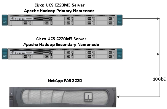
A NetApp FAS2220 storage system running Data ONTAP hosts a mirrored copy of the namenode metadata over a Network File System (NFS) mount, as shown in Figure 76. Notice that the secondary namenode is also connected to the FAS2220 to facilitate namenode recovery to the secondary namenode server, in the event of namenode failure.
Figure 76 NFS Connectivity Between Namenodes and NetApp FAS 2220
E-Series Overview
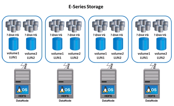
NetApp recommends creating datanode servers on the E-Series array at a ratio of four nodes to one E5460 array, with each node having a single SAS path to one of the storage array controllers.
Figure 77 NetApp E5460 Array
FAS2220 and Data ONTAP 8
Initial setup of the FAS2220 is done with the Data ONTAP command line interface via the console serial port. Once the initial setup is done, further configuration and management of the FAS2220, the Data ONTAP 8 operating system and Data ONTAP features is done via the NetApp OnCommand System Manager management software.
FAS Initial Configuration
Table 6 lists the values for each parameter in the NetApp FAS2220 storage system configuration.
Note
Data ONTAP 8.1.2 7-Mode
1.
Before running the setup script, complete the configuration worksheet that is included in the Data ONTAP® 8.1 Software Setup Guide For 7-Mode, see:
https://library.netapp.com/ecm/ecm_get_file/ECMP1119529
Note
2.
Initial setup of the FAS2220 must be done via the serial console port using the Data ONTAP command line interface.
When Data ONTAP is installed on a new storage system, the following files are not populated:
–
–
–
–
To setup these files, follow these steps:
a.
b.
c.
d.
Please enter the new hostname []: fas2220Do you want to enable IPv6? [n]: RETURNDo you want to configure interface groups? [n]: RETURNPlease enter the IP address for Network Interface e0a []:RETURNe.
f.
Should interface e0a take over a partner IP address during failover? [n]: RETURNPlease enter the IP address for the Network Interface e0b []:EnterShould interface e0b take over a partner IP address during failover? [n]: RETURNPlease enter the IP address for the Network Interface e0c []:EnterShould interface e0c take over a partner IP address during failover? [n]: RETURNPlease enter the IP address for the Network Interface e0d []:EnterShould interface e0d take over a partner IP address during failover? [n]: RETURNPlease enter the IP address for the Network Interface e1a []:EnterShould interface e1a take over a partner IP address during failover? [n]: RETURNPlease enter the IP address for the Network Interface e1b []:EnterShould interface e1b take over a partner IP address during failover? [n]: RETURNPlease enter the IP address for Network Interface e0M []: 10.29.160.43Please enter the netmaskfor the Network Interface e0M [255.255.255.0]: 255.255.255.0Should interface e0M take over a partner IP address during failover? [n]: yPlease enter the IPv4 address or interface name to be taken over by e0M []: e0MPlease enter flow control for e0M {none, receive, send, full} [full]: RETURNWould you like to continue setup through the Web interface? [n]: RETURNPlease enter the name or IP address of the IPv4 default gateway: 10.29.160.1The administration host is given root access to the storage system's / etc files for system administration. To allow /etc root access to all NFS clients enter RETURN below.Please enter the name or IP address for administrative host: RETURNPlease enter timezone [GTM]: US/Pacific
Note
Where is the filer located? Hadoop LabEnter the root directory for HTTP files [home/http]: RETURNDo you want to run DNS resolver? [n]: yPlease enter DNS domain name []: hadoop.localPlease enter the IP address for first nameserver []: 10.29.160.53Do you want another nameserver? [n]: RETURN
Note
Do you want to run NIS client? [n]: RETURNPress the Return key to continue through AutoSupport messagewould you like to configure SP LAN interface [y]: RETURNWould you like to enable DHCP on the SP LAN interface [y]: nPlease enter the IP address for the SP: RETURNPlease enter the netmask for the SP []:RETURNPlease enter the IP address for the SP gateway: RETURNPlease enter the name or IP address of the mail host [mailhost]: <<var_mailhost>>Please enter the IP address for <<var_mailhost>> []:<<var_mailhost>>New password: change_meRetype new password: change_meg.
h.
i.
To configure the FAS2220 to serve NFS data by creating two NFS shares, follow these steps:
1.
2.
aggr add aggr0 23.
vol size vol0 200g4.
vol create fsimage_bkp aggr0 100gvol create common aggr0 100g5.
exportfs -p
sec=sys,rw=192.168.11.0/24:192.168.12.0/24,root=192.168.11.0/24:192.168.12.0/24
/vol/fsimage_bkp
exportfs -p sec=sys,rw=192.168.11.0/24:192.168.12.0/24,root=192.168.11.0/24:192.168.12.0/24 /vol/commonNetApp OnCommand System Manager 2.1
OnCommand® System Manager is the simple yet powerful browser-based management tool that enables administrators to easily configure and manage individual NetApp storage systems or clusters of systems.
System Manager is designed with wizards and workflows, simplifying common storage tasks such as creating volumes, LUNS, qtrees, shares, and exports, which saves time and prevents errors. System Manager works across all NetApp storage: FAS2000, 3000, and 6000 series as well as V-Series systems.
The following are NetApp OnCommand System Manager 2.1 prerequisites:
•
•
•
–
–
Launch OnCommand System Manager
Double-click the System Manager icon on your desktop to launch System Manager. The NetApp OnCommand System Manager icon is shown in Figure 78.
Figure 78 NetApp OnCommand System Manager Icon
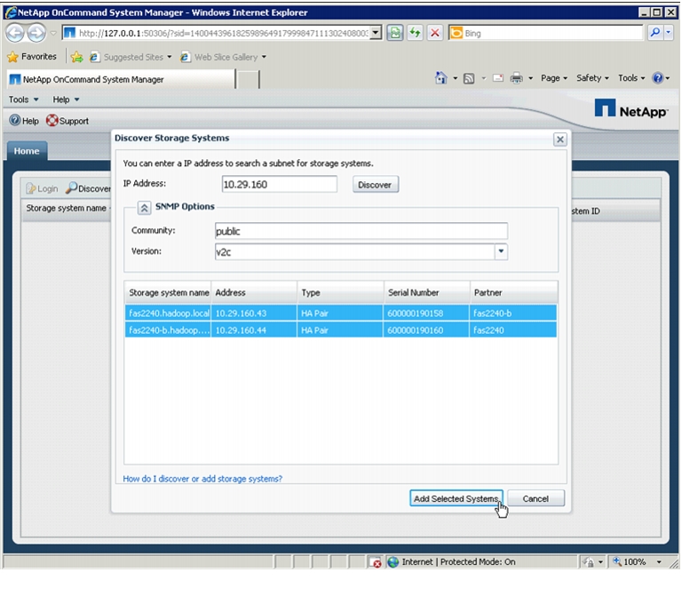
Discover Storage Systems
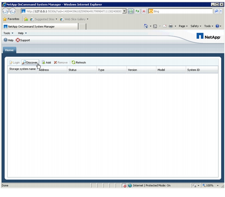
To add storage system or HA pair, follow these steps:
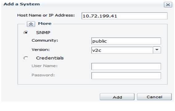
1.
Figure 79 Discovering Storage Systems
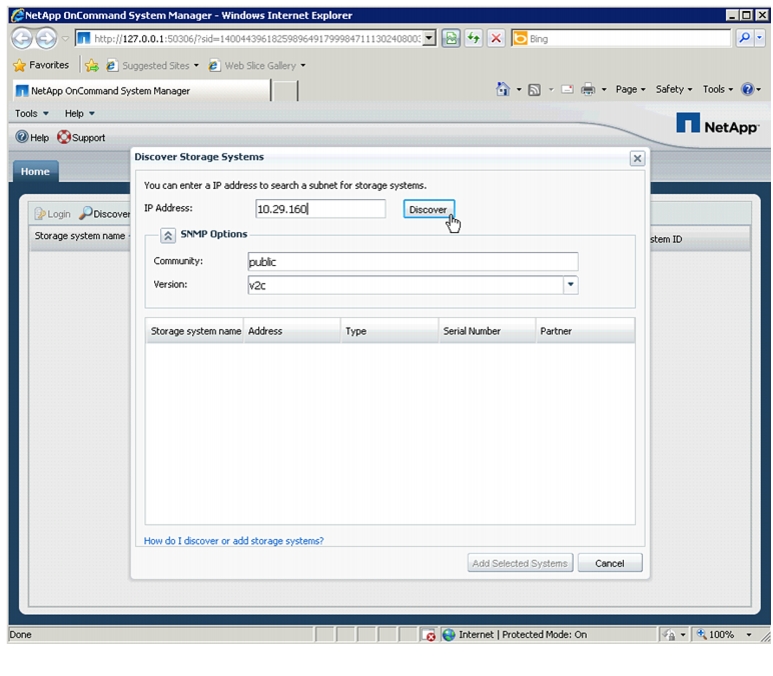
2.
Figure 80 Entering the IP Address for Discovering Storage Systems
3.
Figure 81 Adding Selected Storage Systems
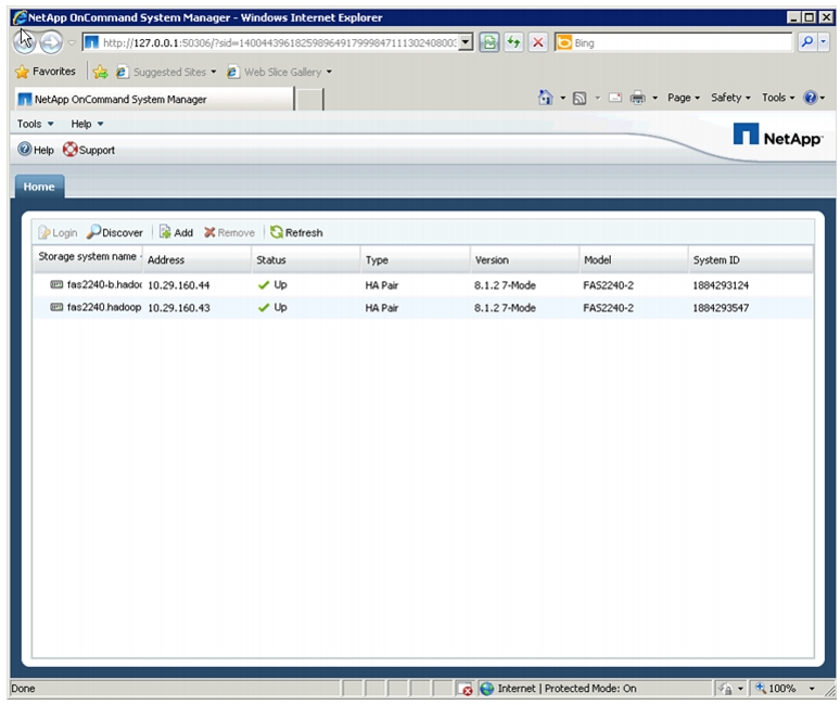
4.
Figure 82 Verifying the Added Storage Systems
Adding Storage Systems
If you need to add a FAS unit to an existing System Manager setup, follow these steps within System Manager:
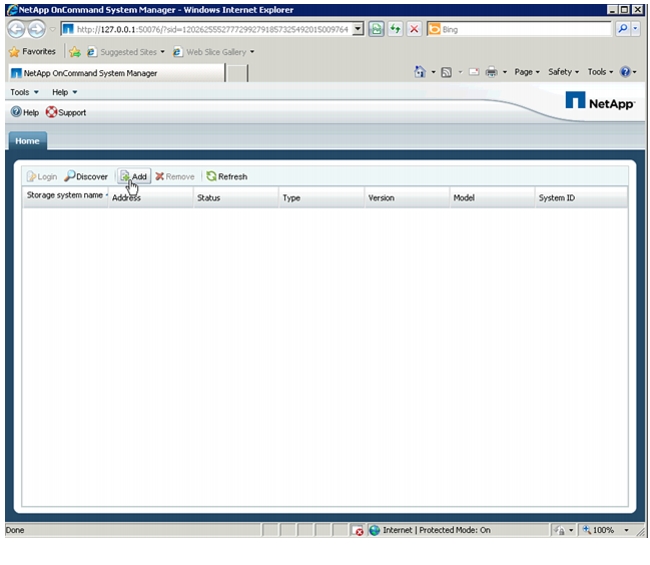
1.
Figure 83 Adding FAS Storage Unit
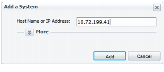
2.
Figure 84 Entering Host IP Address
3.
.
4.
5.
Figure 85 Specifying SNMP Details
6.
7.
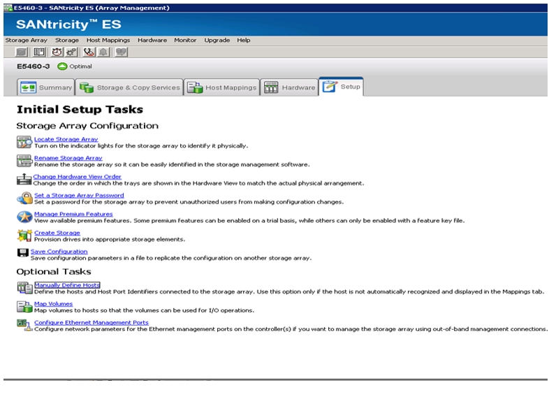
E-Series Configuration & Management
The configuration and management of the E-Series E5460 storage array is done via the NetApp SANtricity management software.
Record Storage Configurations
Use the template in Table 7 to capture and keep a record of all volume groups, volumes, serving controllers, and Hadoop datanode hosts. The entries in the Table 7 are intended to serve as an example of a useful naming convention; however, individual customer requirements vary widely with respect to naming conventions. As a result, the specific names for individual projects should be substituted for those in the example template.
Note
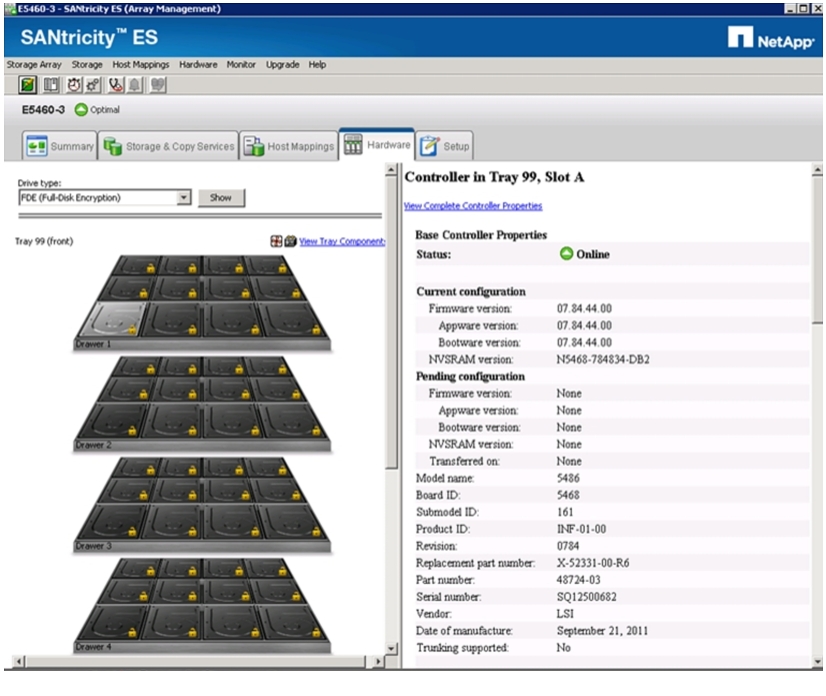
Confirm That All Disks Are in Optimal Status
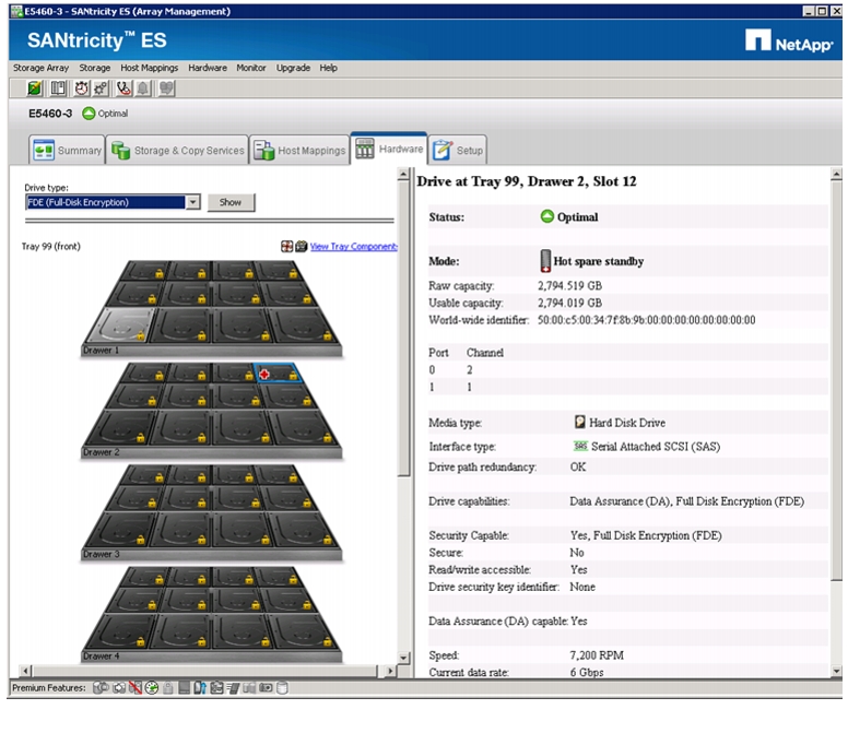
To confirm the health status of all disks, follow these steps:
1.
Figure 86 Hard Disk Details in SANtricity ES Manager
2.
, for the health of all drives and look for any errors. If there are no errors, proceed to the next step. If fault conditions are present, correct the faults before proceeding.
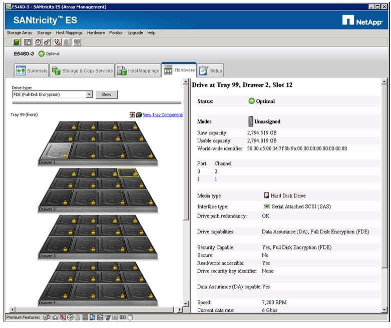
Selecting Drives for Volume Groups and Hot Spares
For highest performance, NetApp recommends balancing the use of even and odd disk slots for each controller, which provides balanced I/O across drive side channels. Table 8 defines the correct mapping of disk drives to volume groups.
Note
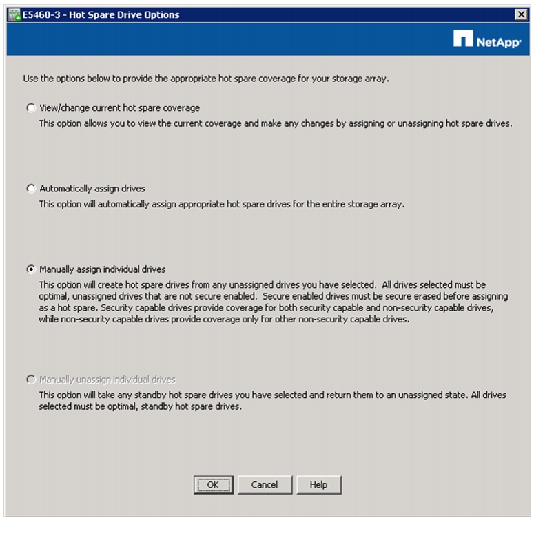
Creating and Assigning Hot Spares
To allocate hot spares in the E-Series array, follow these steps:
1.
2.
3.
4.
a.
b.
c.
d.
Figure 87 Selecting a Drive as Spare
Note
e.
f.
Figure 88 Assigning Drives Manually
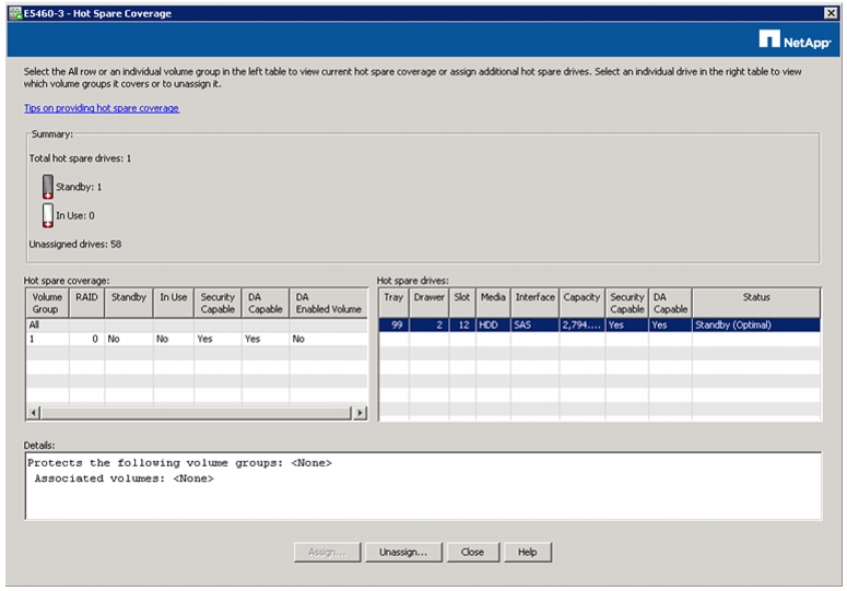
Figure 89 shows assigned Hot spare in standby mode in the SANtricity Manager window.
Figure 89 Hot Spare in Standby Mode
5.
a.
b.
c.
Figure 90 Summary Showing Total Hot Spare Drives
Creating Volume Groups
A volume group is a set of disk drives that are logically grouped together to provide storage with a single RAID level for all volumes in the group. Every E-Series storage array has eight RAID 5 volume groups of 6+1 disks (6 data disks and 1 parity disk). This leaves all 60 disks assigned in each shelf given the four hot spare drives previously prescribed.
To create the volume groups, select the disks from across the five drawers starting with drawer one, slot one and alternating between odd and even slot numbers as the disks are selected in a round robin fashion. For more details on Hot spares, see "Selecting Drives for Volume Groups and Hot Spares" section.
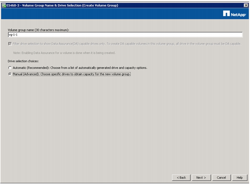
Creating New Volume Groups
To create a volume group, follow these steps:
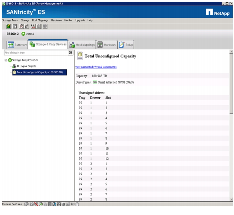
1.
a.
b.
Figure 91 Array Management Window Showing Unassigned Drive Details
c.
d.
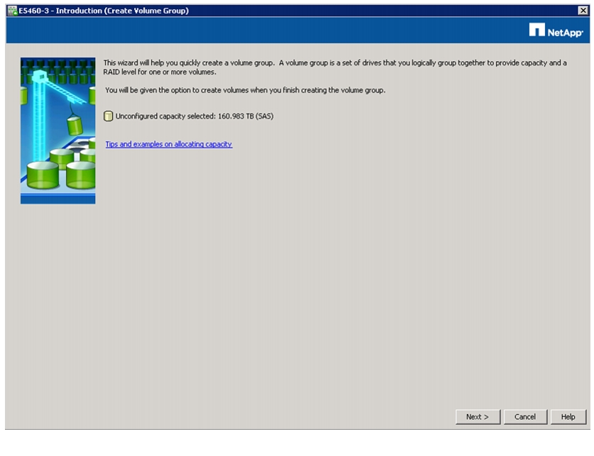
2.
Figure 92 Creating Volume Group Wizard
3.
a.
Note
b.
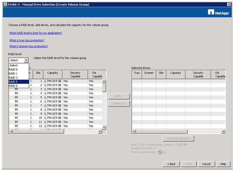
Figure 93 Manual Drive Selection
c.
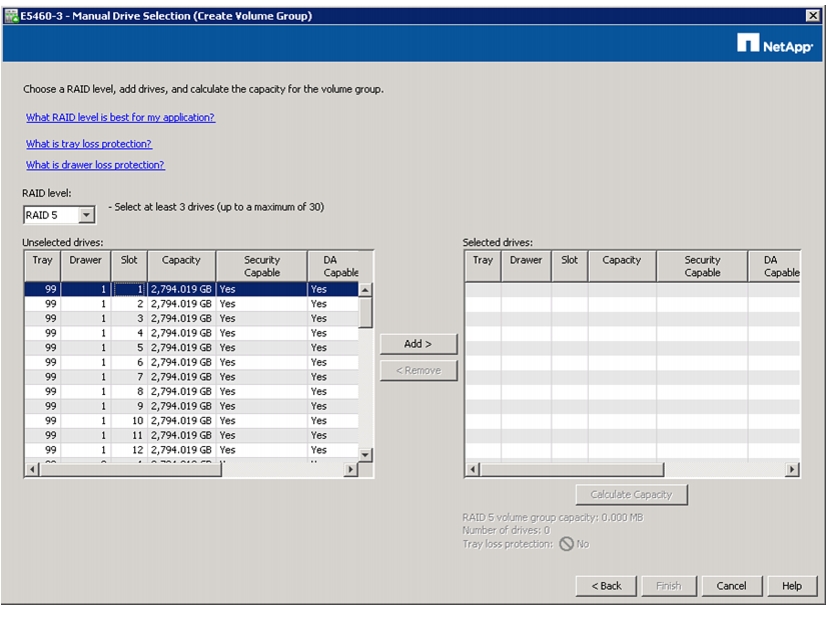
Figure 94 Selecting RAID Levels for Volume Group
d.
to add desired disks to the volume group.
Figure 95 Adding Drives for Volume Group
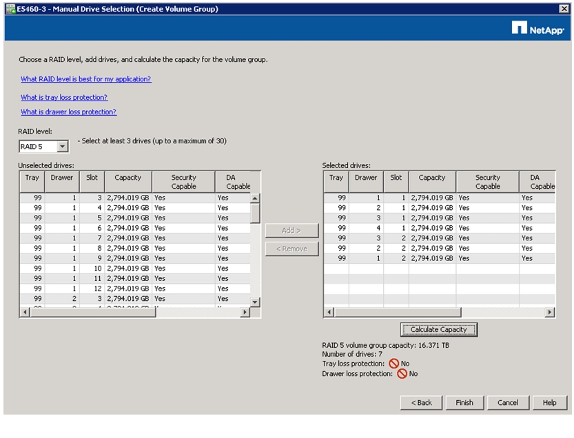
e.
f.
Figure 96 Calculating the Volume Group Capacity
g.
h.
Figure 97 Selected Drives Added Successfully to the Volume Group
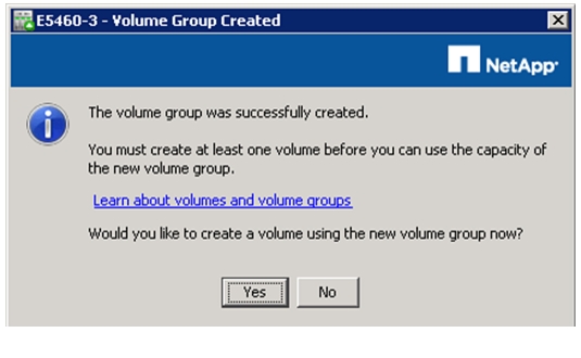
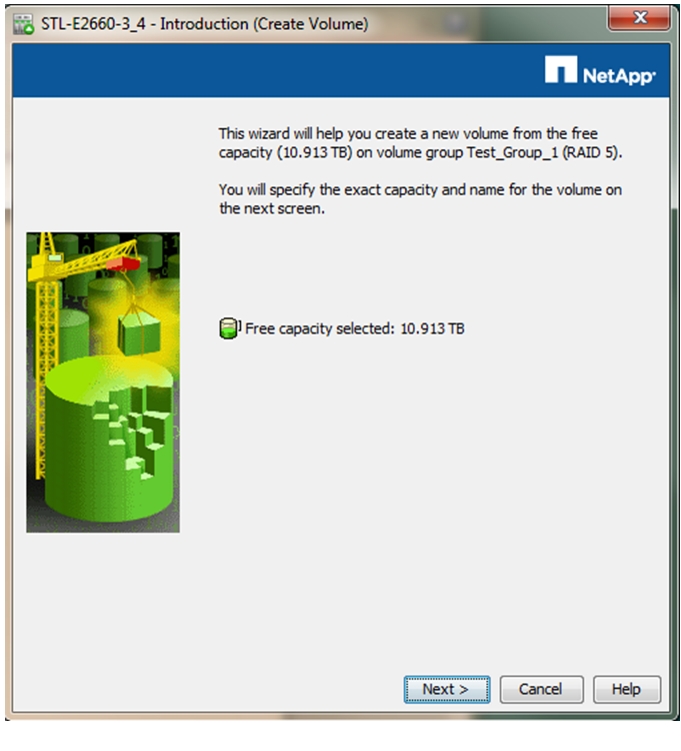
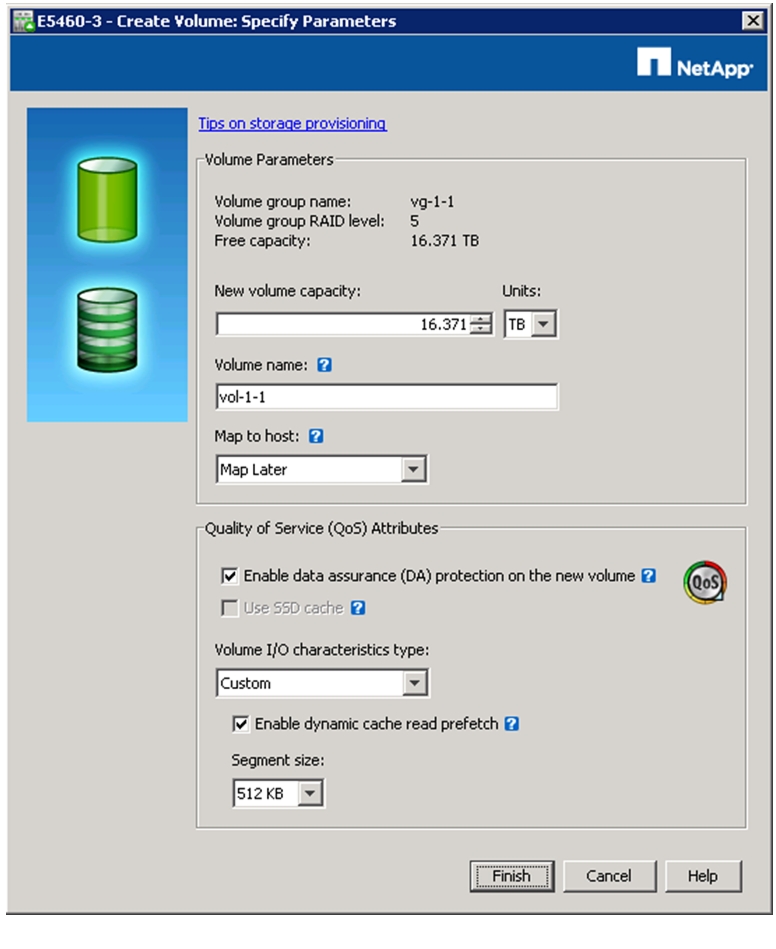
Create New Volume
To create new volume, follow these steps:
1.
Figure 98 Creating Volume
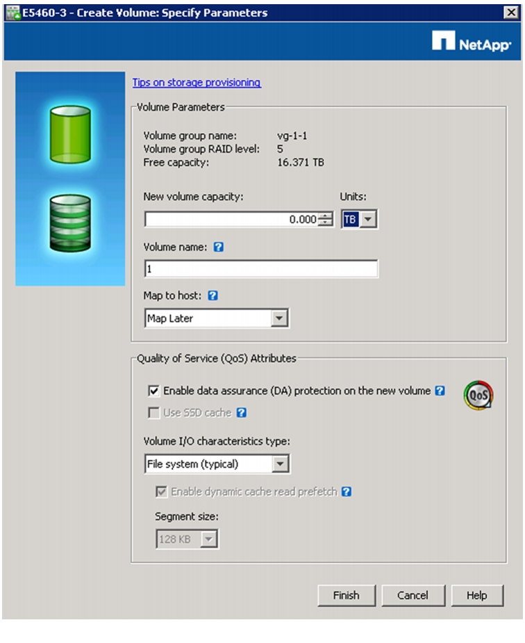
2.
a.
Figure 99 Entering Volume Parameters
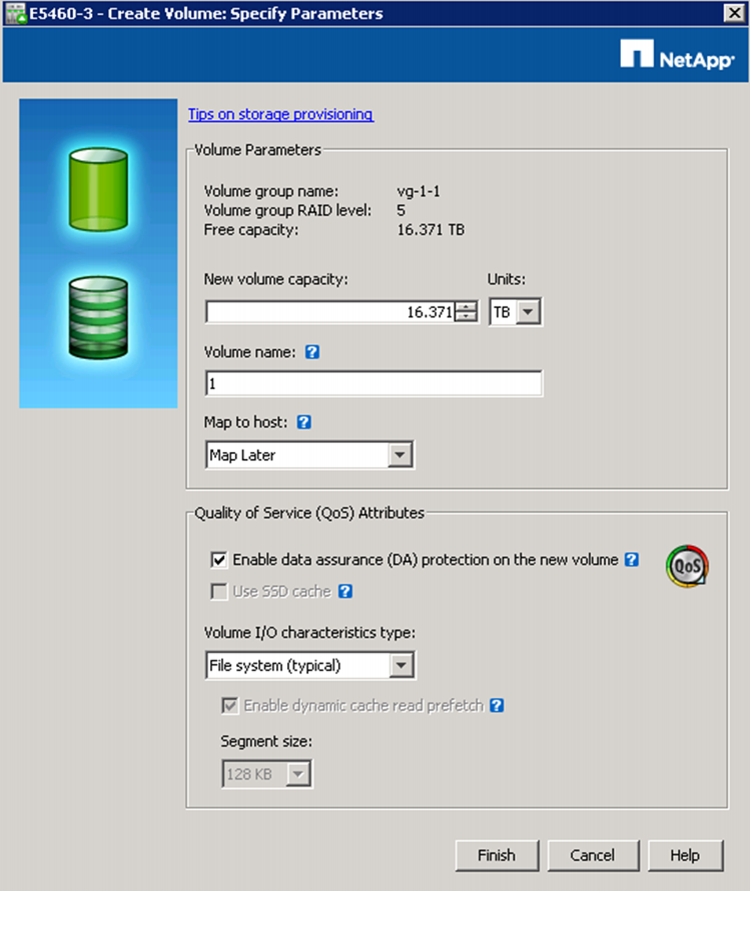
b.
Figure 100 Specifying New Volume Capacity
c.
d.
Note
3.
a.
b.
Figure 101 Setting QoS Attributes for Volume
c.
d.
4.
Figure 102 Volume Group and Volume Capacity Details
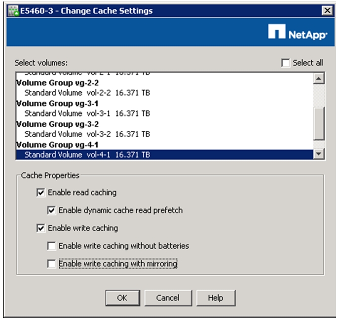
5.
a.
Figure 103 Cache Settings
6.
a.
b.
c.
Note
Figure 104 Verifying Cache Settings
d.
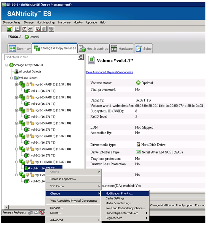
7.
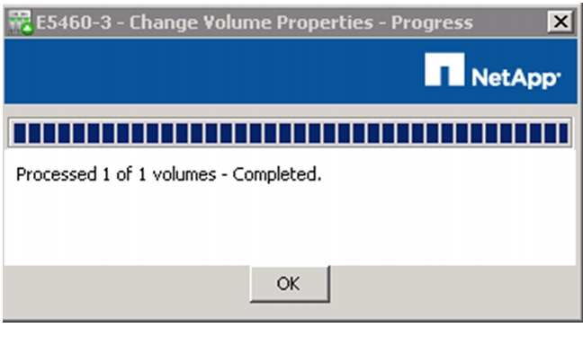
8.
Figure 105 Changing Volume Properties
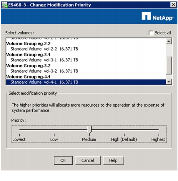
9.
Figure 106 Priority Settings
10.
Figure 107 Allocating Resources Based on Priority Chosen
11.
12.
Table 9 provides the standard storage configuration:
After the volumes are created and the LUNs are available, the LUNs must be mapped to datanodes (hosts). It is critically important that each host has exclusive access to its LUNs through the assigned controller. NetApp strongly recommends using a naming convention that reflects the host-to-volume mappings.
Map Datanodes to E-Series SAS Ports
You need to determine the SAS port addresses of the datanodes and how they map to the SAS ports of the E-Series controllers. To map SAS ports of E-series controllers with the datanodes, follow these steps:
1.
2.
3.
4.
Identify SAS Port ID Using LSI SAS2Flash Utility
The sas2flash utility is a product of LSI Corporation. It is designed to support the LSI SAS 9207-8e HBA installed in each host attached to the E5460 arrays, primarily to display the Port IDs assigned to the SAS host bus adapter (HBA) ports or to periodically update the BIOS and firmware on the HBA.
The sas2flash utility usually comes bundled with the following items:
•
•
•
•
•
Issue the following command to list the port ID of the LSI SAS HBA:
./sas2flash -listOutput will look similar to this:Version 11.00.00.00 (2011.08.22)Copyright (c) 2008-2011 LSI Corporation. All rights reservedAdapter Selected is a LSI SAS: SAS2008(B2)Controller Number : 0Controller : SAS2008(B2)PCI Address : 00:02:00:00SAS Address : 500605b-0-0266-1880NVDATA Version (Default) : 0a.03.00.02NVDATA Version (Persistent) : 0a.03.00.02Firmware Product ID : 0x2213Firmware Version : 11.00.00.00NVDATA Vendor : LSINVDATA Product ID : SAS9207-8eBIOS Version : 07.21.00.00UEFI BSD Version : 04.30.03.00FCODE Version : N/ABoard Name : 9200-3080Board Assembly : H3-25217-00CBoard Tracer Number : SP10414124Finished Processing Commands Successfully.Exiting SAS2Flash.
Note
Map Datanodes to SAS Port IDs
After the SAS Port IDs for the datanode servers have been identified, map those IDs to the SAS ports on the E-Series storage array. Use the SANtricity ES Storage Manager to perform the mapping.
To map the datanodes, follow these steps:
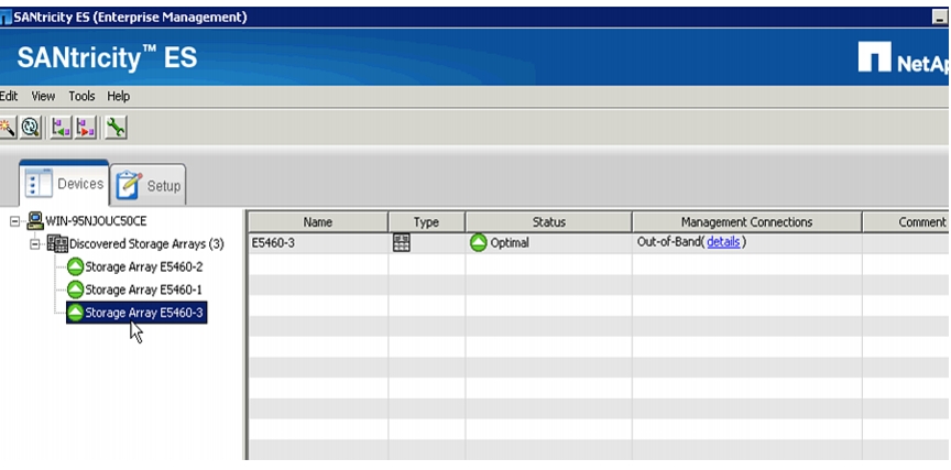
1.
2.
Figure 108 Discovered Storage Array
Note
Hosts can be mapped using two different methods:
–
–
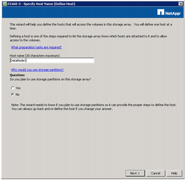
3.
Figure 109 Defining Host Manually
4.
Figure 110 Entering Host Details
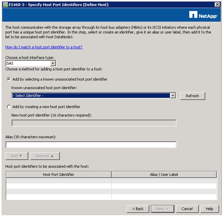
5.
6.
7.
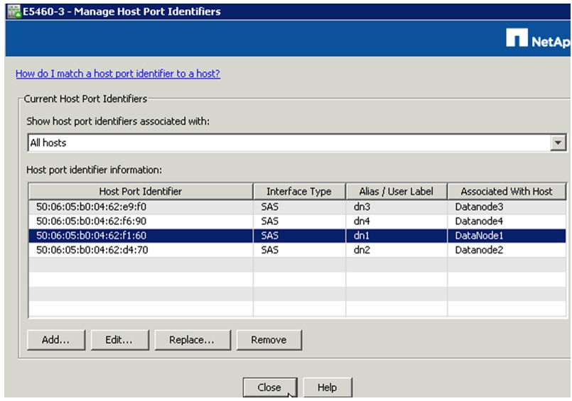
Figure 111 Entering Host Port Identifiers
Note
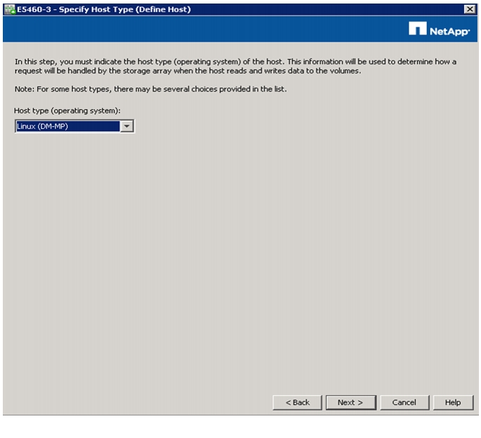
8.
9.
10.
Figure 112 Specifying Host Type
11.
12.
Figure 113 Summary of Host Port Identifiers
Note
E-Series Disk Initialization
The disk initialization format is set to Immediate Availability Format (IAF) by default. When the disk initialization time, which can take more than 24 hours, can be a concern, NetApp recommends that IAF be disabled. This change blocks writes to the disks during the initialization process; however, the initialization process shortens dramatically. The decrease in initialization time ranges from minutes to several hours, depending on the size of the volume groups.
Note
To disable the IAF disk initialization setting, follow these steps:
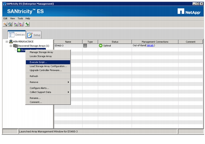
1.
Figure 114 Selecting Execute Script to Verify Disk Initialization
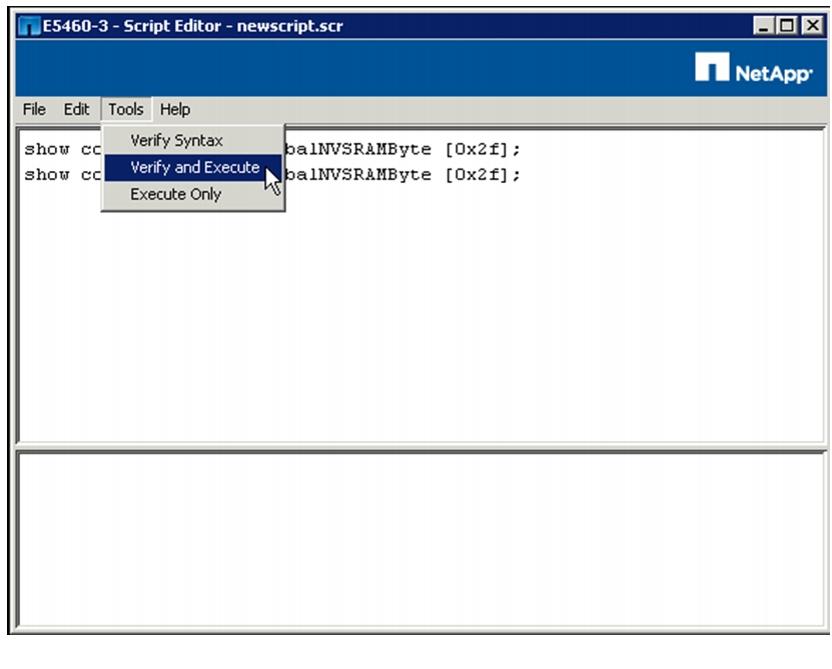
2.
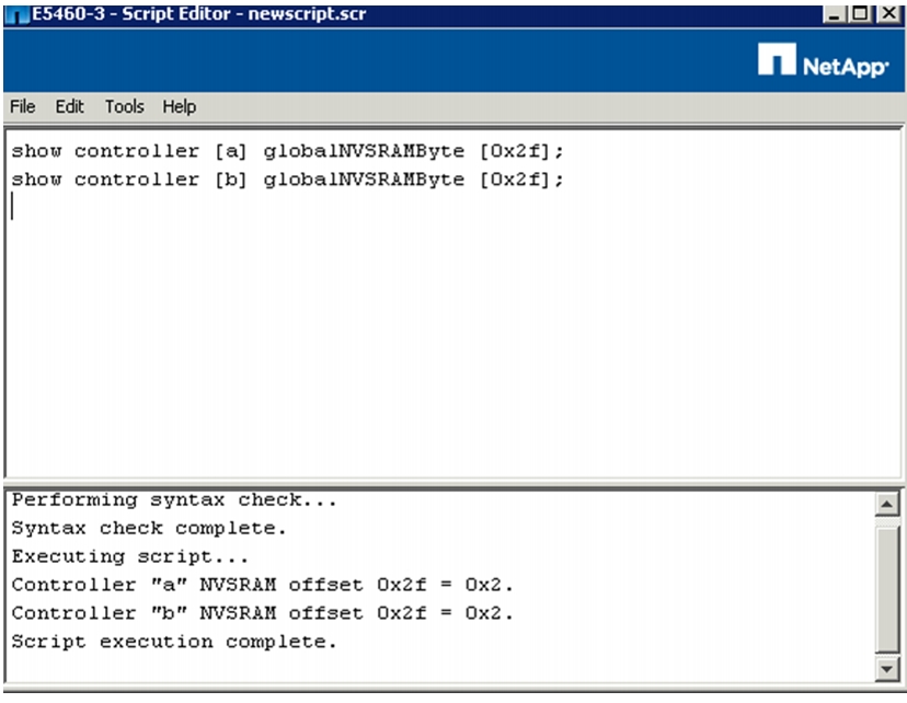
show controller [a] globalNVSRAMByte [0x2f];show controller [b] globalNVSRAMByte [0x2f];3.
Figure 115 Execute Commands and Verify
4.
set controller [a] globalNVSRAMByte [0x2f] = 0x02, 0x02;set controller [b] globalNVSRAMByte [0x2f] = 0x02, 0x02;5.
6.
Figure 116 Completion of Script Execution
Note
Disable E-Series Auto Volume Transfer
Auto volume transfer (AVT) is a feature of E-Series firmware that enables storage controller failover in the event that a controller becomes unavailable to datanodes. With the FlexPod Select for Hadoop, datanodes are directly connected to storage controllers using a single SAS cable. AVT is not applicable to this configuration, because connectivity to storage provides no redundancy. Failure of an E5460 controller is handled by the self-healing capability of Hadoop. Self-healing is supported by HDFS replication, which results in multiple copies of data being locally available to other nodes in the cluster. If a controller fails, MapReduce tasks using storage on that controller are reassigned to other healthy nodes in the Hadoop cluster that have access to another copy of the missing data. Since AVT adds no value to FlexPod Select for Hadoop, NetApp recommends that it be disabled.
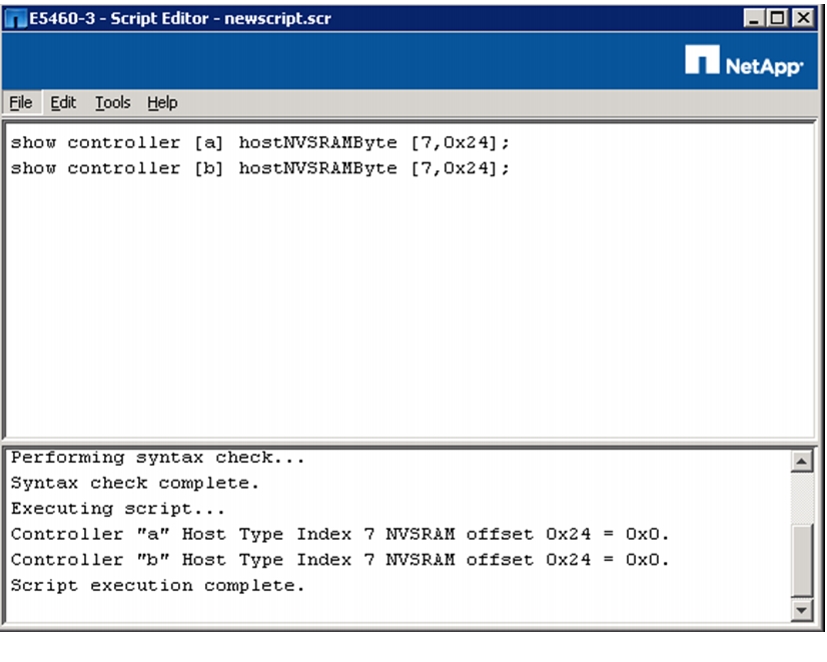
To disable AVT, follow these steps:
1.
2.
show controller [a] hostNVSRAMByte [7,0x24];show controller [b] hostNVSRAMByte [7,0x24];3.
4.
set controller [a] hostNVSRAMByte[7,0x24]=0x00;set controller [b] hostNVSRAMByte[7,0x24]=0x00;5.
6.
Confirm the settings have been updated to 0x0 for both controllers.
Figure 117 Completion of Script Execution
7.
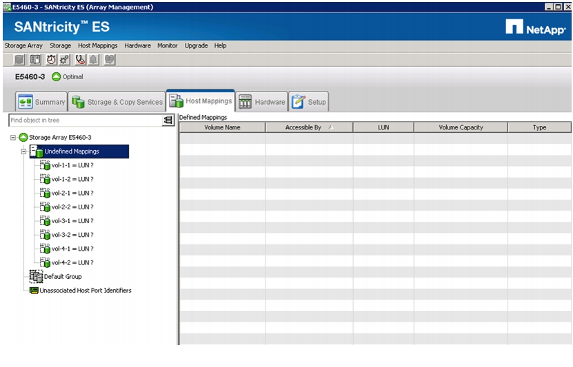
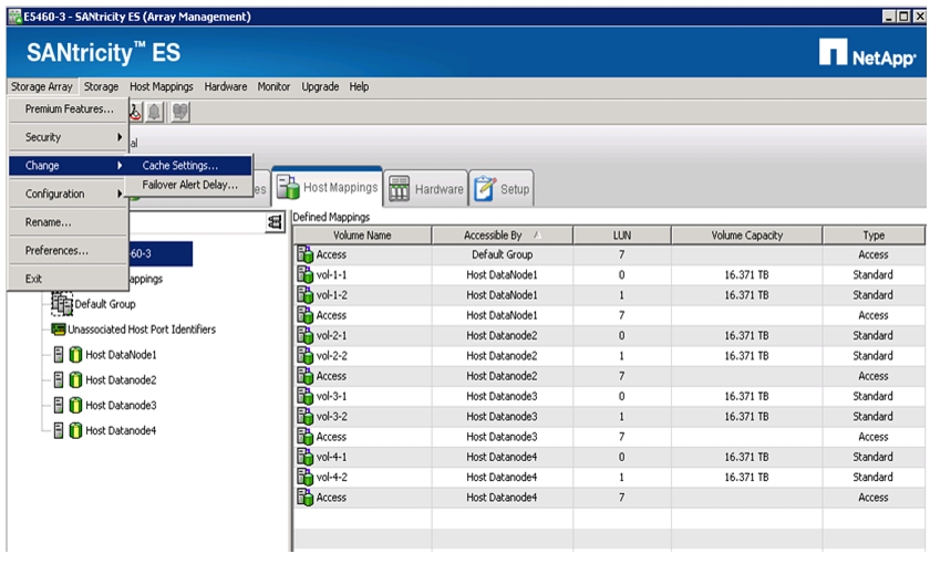
Map Volumes
To map the volumes to the assigned datanode, follow these steps:
1.
Figure 118 Unmapped LUNs
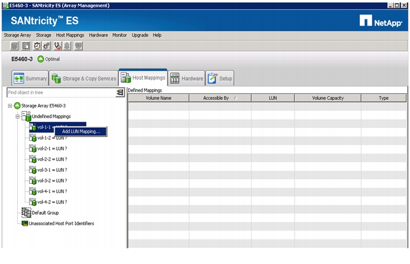
2.
Figure 119 Adding LUN Mapping
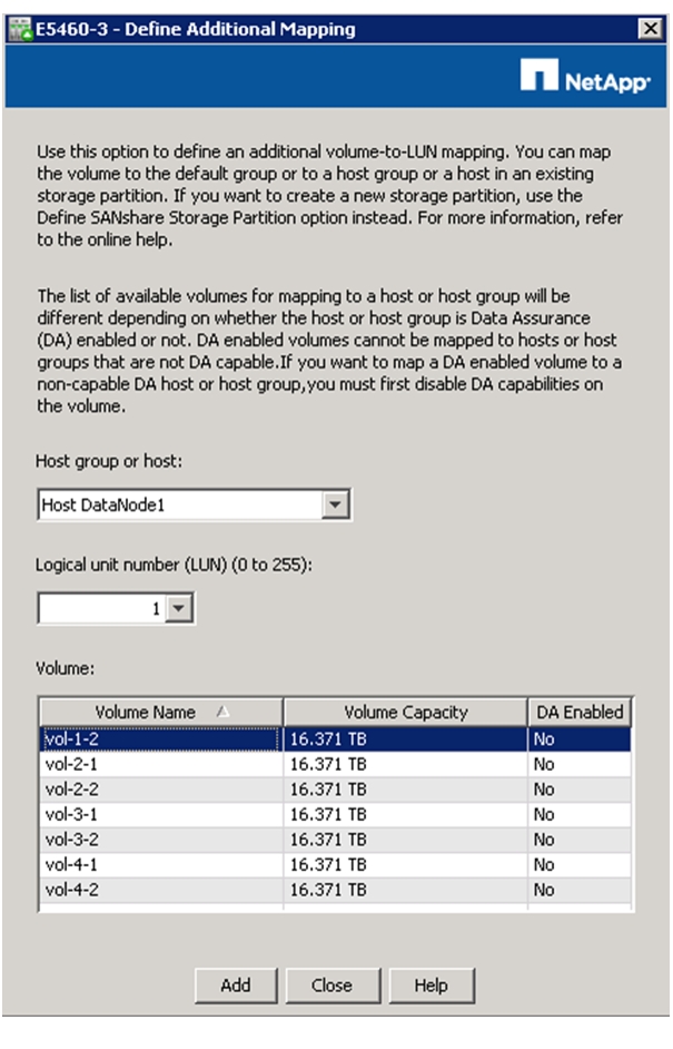
3.
a.
b.
c.
Figure 120 Entering Additional Mapping Information
d.
e.
Note
4.
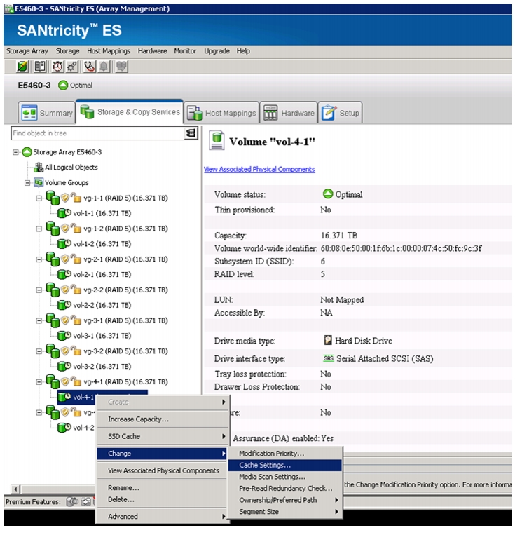
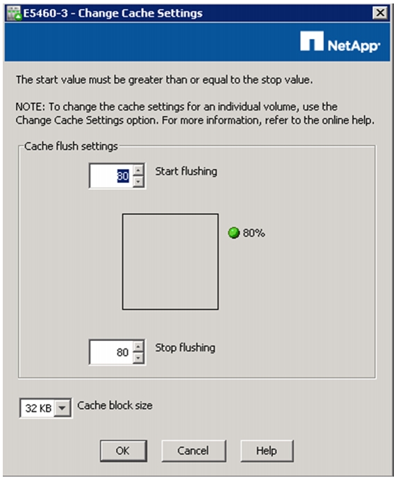
Configure Cache Settings for Array
To configure caching for the entire storage array, follow these steps:
1.
Figure 121 Cache Settings
2.
Figure 122 Changing the Cache Block Size
Note
This completes the E5460 initialization and storage configuration.
DataNode File Systems on E5460 LUNs
Once the E5460 systems have finished their initialization, it is time to create partition tables and file systems on the LUNs supplied to each of the datanodes.
The following script should be run as root user on each of the datanodes:
#!/bin/bash[[ "-x" == "${1}" ]] && set -x && set -v && shift 1# rescan scsi devsfor X in /sys/class/scsi_host/host?/scandoecho '- - -' > ${X}done# find new LUNsfor X in /dev/sd?doecho $Xif [[ -b ${X} && `/sbin/parted -s ${X} print quit|/bin/grep -c boot` -ne 0 ]]thenecho "$X bootable - skipping."continueelseY=${X##*/}1/sbin/parted -s ${X} mklabel gpt quit/sbin/parted -s ${X} mkpart 1 6144s 100% quit/sbin/mkfs.xfs -f -q -l size=65536b,lazy-count=1,su=256k -d sunit=1024,swidth=6144 -r extsize=256k -L ${Y} ${X}1(( $? )) && continue/bin/mkdir -p /CDH/${Y}(( $? )) && continue/bin/mount -t xfs -o allocsize=128m,noatime,nobarrier,nodiratime ${X}1 /CDH/${Y}(( $? )) && continueecho "LABEL=${Y} /CDH/${Y} xfs allocsize=128m,noatime,nobarrier,nodiratime 0 2" >> /etc/fstabfidoneCloudera Manager and Cloudera Enterprise Core Installation
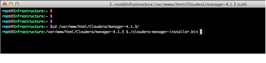
Installing Cloudera Manager
The Cloudera Manager Installer is used for installing the Cloudera Manager and the Cloudera Enterprise Core software on our cluster. The installation is performed on the infrastructure node. Follow these steps to install the Cloudera Manager:
1.
Figure 123 Starting Cloudera Manager Installer
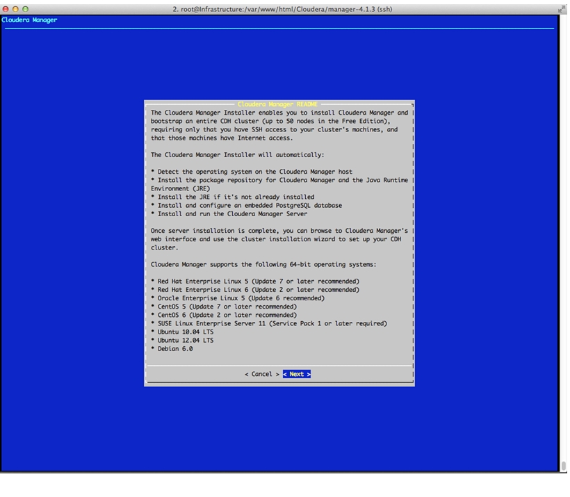
2.
Figure 124 Cloudera Manager Installer
3.
4.
5.
6.
7.
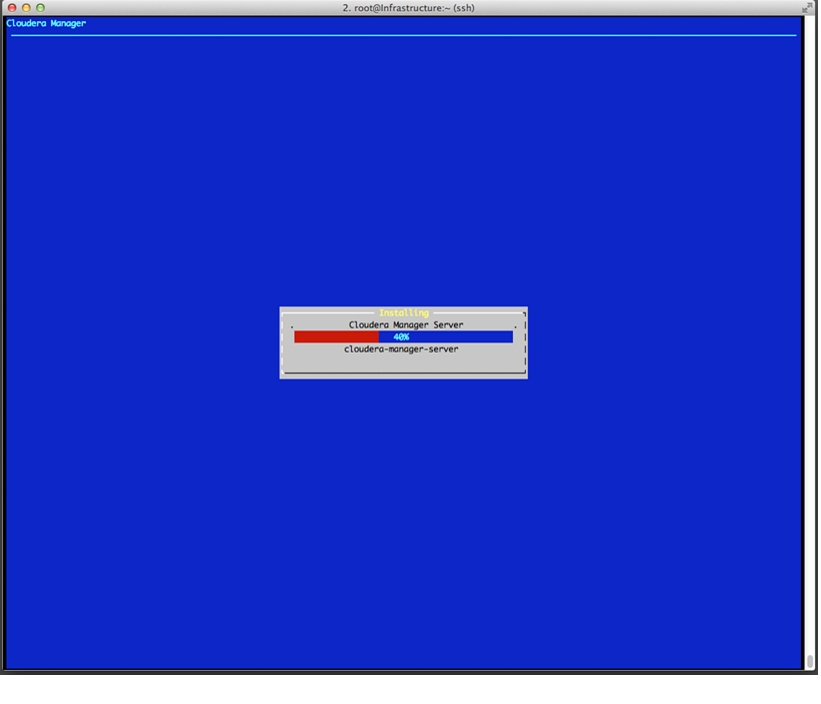
Figure 125 Installation In Progress
8.
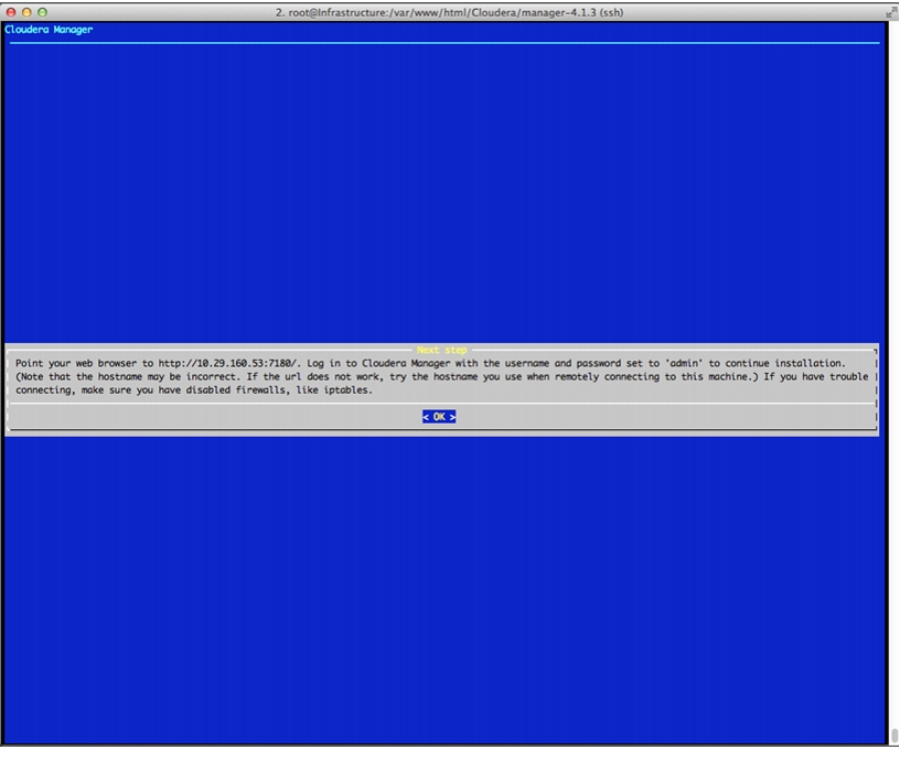
Figure 126 Cloudera Manager URL
9.
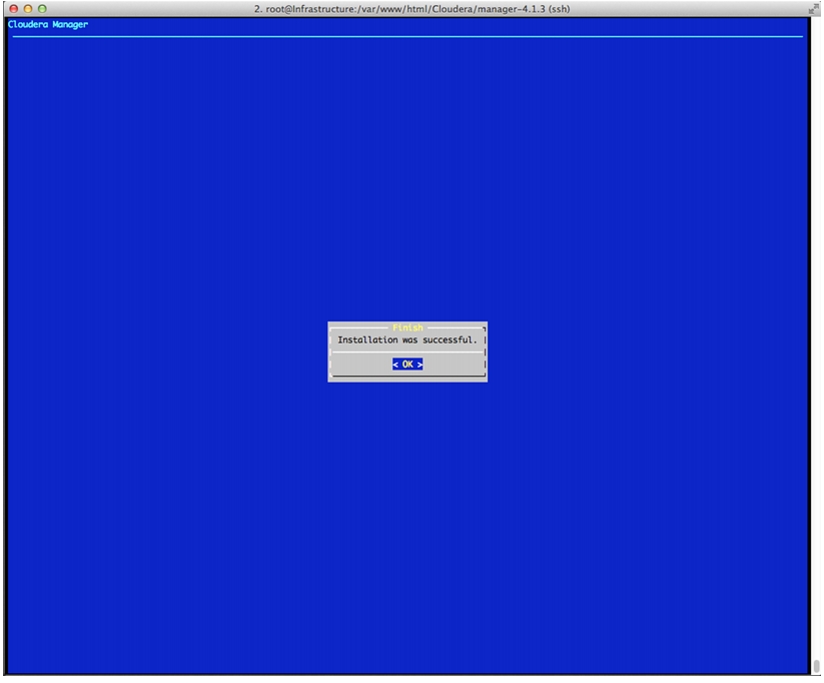
Figure 127 Cloudera Manager is Installed on the Cluster
Install Cloudera Enterprise Core (CDH4)
To install Cloudera Enterprise Core, follow these steps:
1.
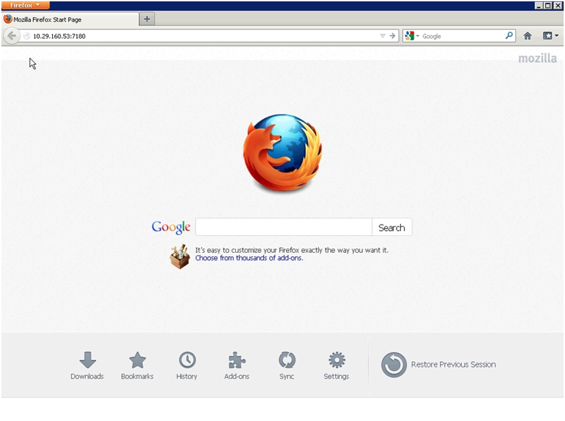
Figure 128 Starting Cloudera Manager
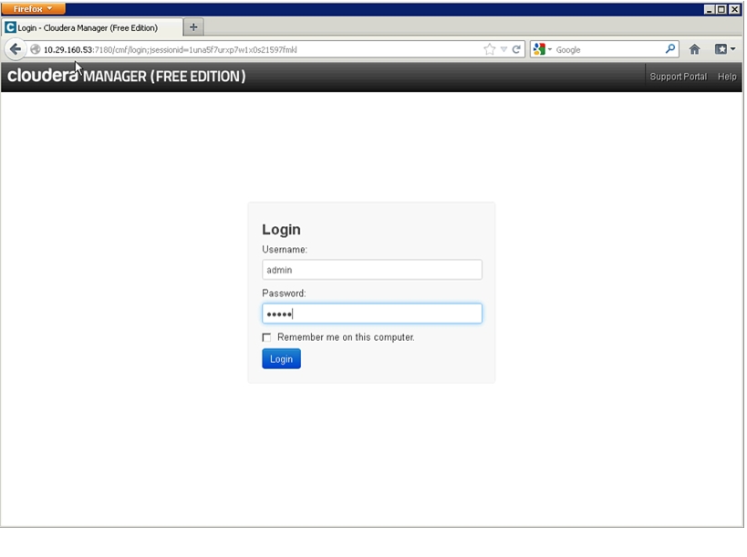
2.
3.
Figure 129 Cloudera Manager Login page
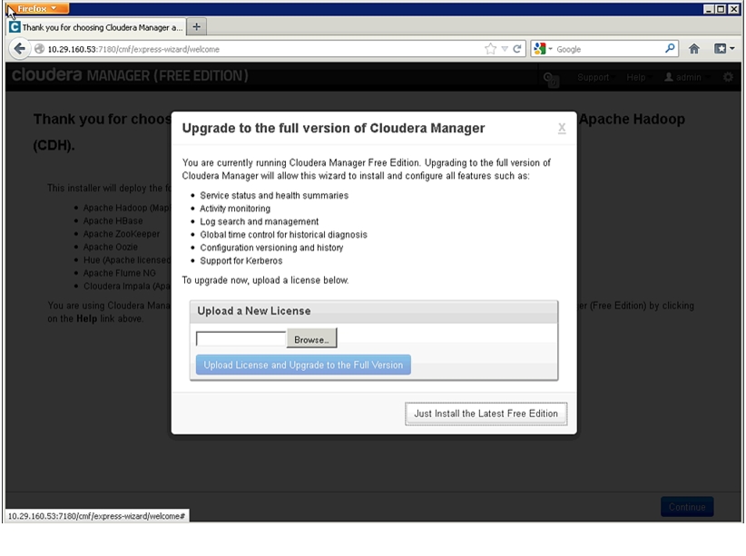
4.
5.
Figure 130 Installing Cloudera Manager
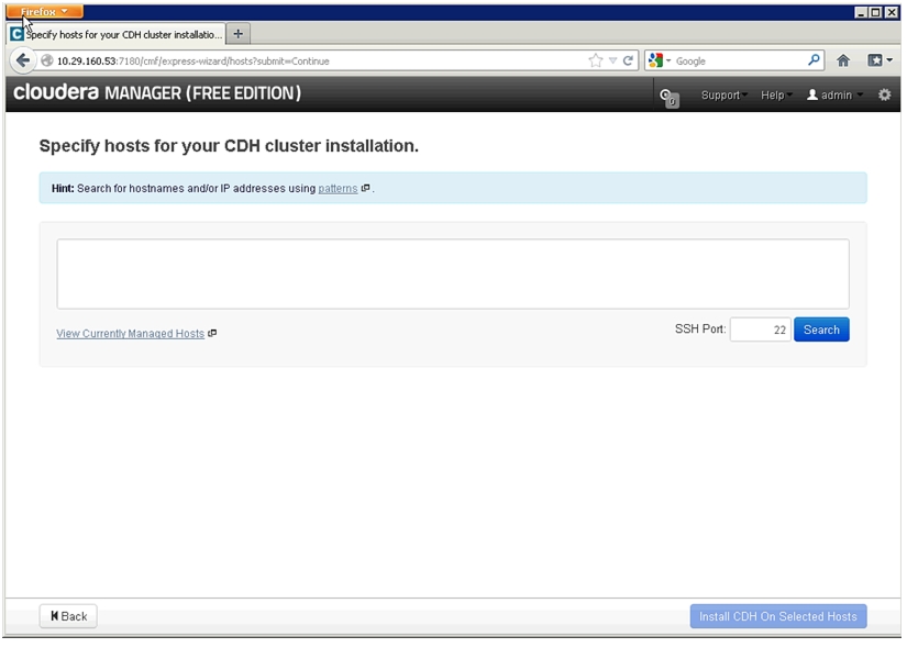
6.
7.
Figure 131 Specifying SSH Port
8.
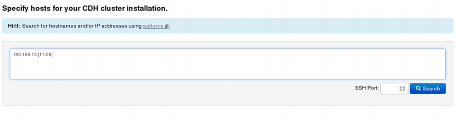
9.
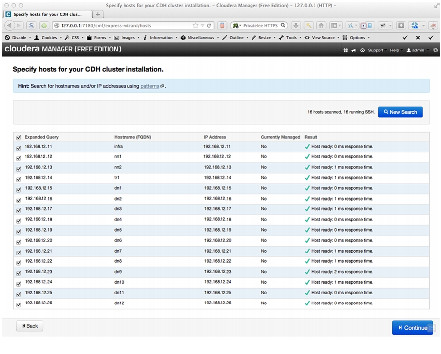
Figure 132 Searching for Cluster Nodes
10.
11.
Figure 133 Verifying and Selecting the Hosts
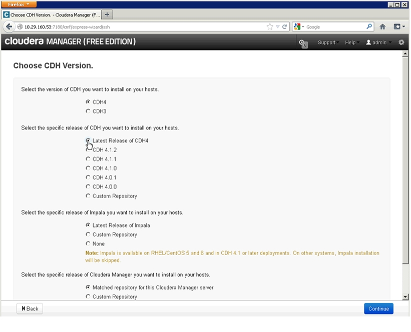
12.
Figure 134 Selecting the CDH Version
13.
14.
Figure 135 Selecting Specific CDH Release
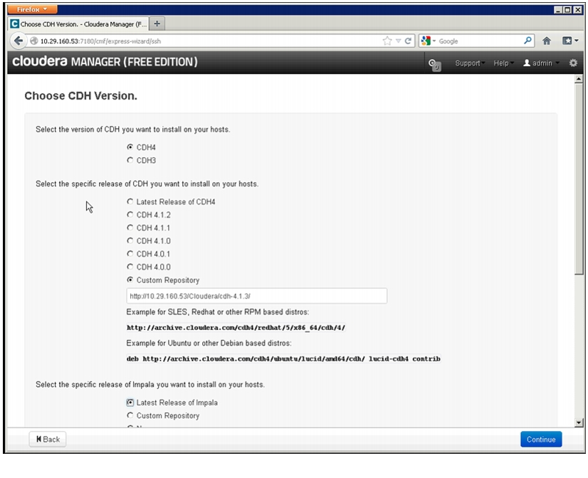
15.
16.
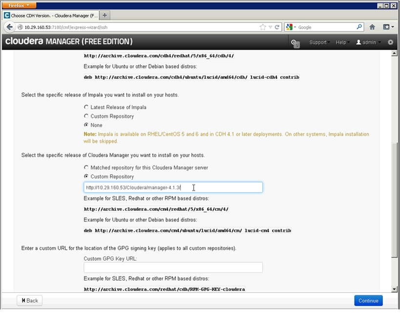
17.
18.
Figure 136 Other Installation Details for the Cluster
19.
20.
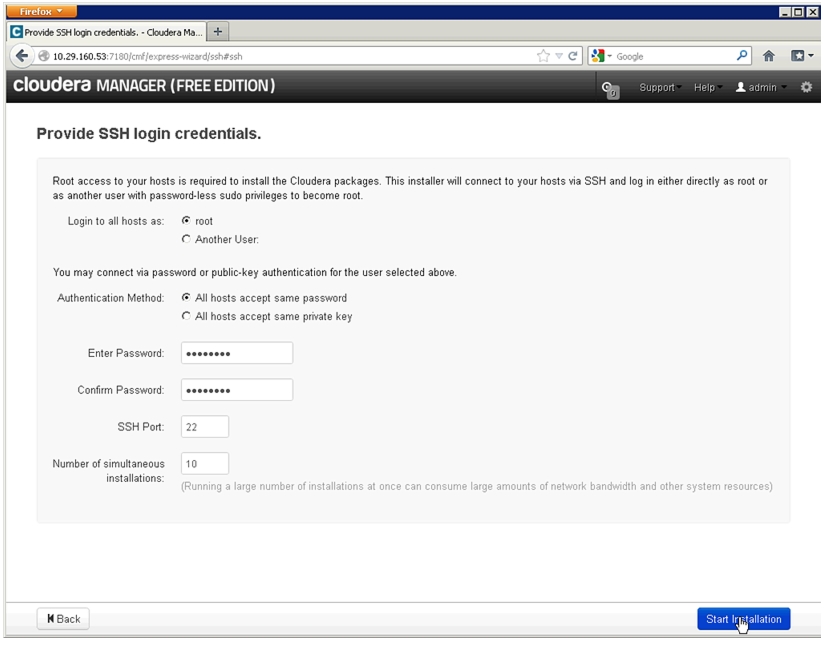
21.
22.
Figure 137 Login Credentials to Start CDH Installation
23.
24.
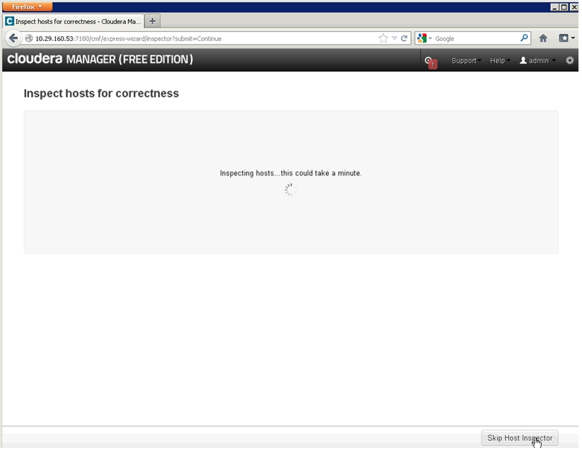
25.
Figure 138 Inspecting Hosts
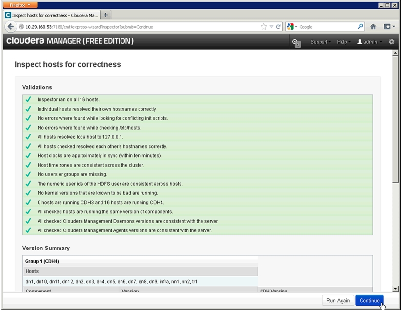
26.
Figure 139 Inspecting Hosts for Correctness
27.
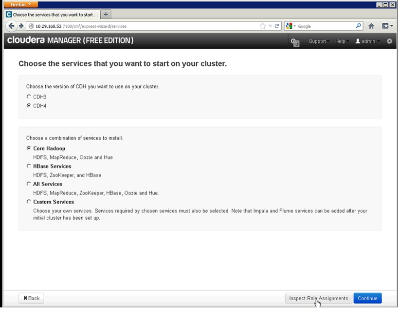
28.
Figure 140 Selecting CDH Version and Services
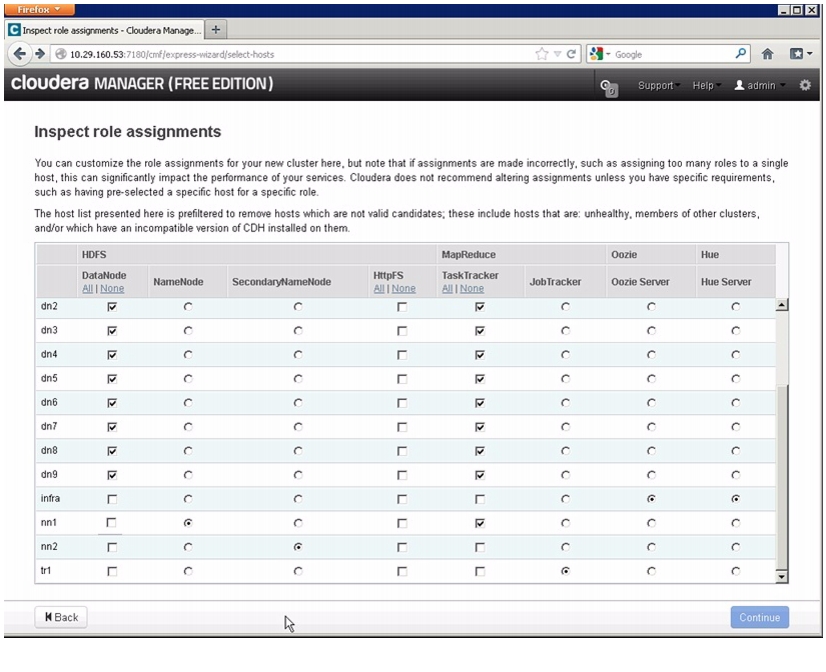
29.
Figure 141 Reviewing the Role Assignments
30.
31.
32.
33.
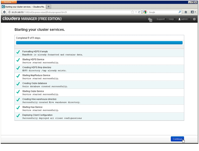
34.
Figure 142 Cluster Services are Ready
35.
Conclusion
FlexPod Select for Hadoop is an innovative solution that combines technologies from the market leaders to enhance reliability and capacity. The fully redundant fabric architecture with industry-leading namenode resiliency, RAID protection with data replication and hot-swappable spares can significantly lower the risk of failure and application downtime. Leading edge Hadoop management tools provide an analytic stack for big data that is highly reliable, scalable and easier to operate.
The solution addresses today's data-driven environment, in which complex and large data sets need to be processed quickly and efficiently. Seamless data and management integration capabilities co-exist with FlexPod running enterprise applications such as Oracle®, Microsoft®, and SAP®, among many others. Compatibility with traditional FlexPod deployments, that is, the existing resources, can still be used and extended. The solution is offered in a master and an expansion configuration for easy scaling. This is a pre-validated solution that enables quick and easy deployment.
Bill of Materials
The FlexPod Select for Hadoop is offered in a master configuration and an expansion configuration for easy scaling.
Up to 160 servers, 2560 processor cores, and up to 10 petabytes of user storage capacity is supported in one single domain. Applications that need to scale beyond one domain can interconnect several UCS domains using Cisco Nexus Series switches. Scalable to thousands of servers and hundreds of petabytes of data, these domains can be managed from a single pane by using UCS Central in a data center or in remote global locations.
This section provides the hardware and software specifications for deploying the FlexPod Select for Hadoop.
Cisco Bill of Materials
Table 11 provides Cisco BOM for both master rack and expansion rack solutions.
*Select appropriate cables based on distance to base rack(8 uplinks from N2K to UCS6296)NetApp Bill of Materials
Table 12 provides NetApp BOM for both master rack and expansion rack solutions.
Related Information
Table 13 provides information on RHEL specifications for both master rack and expansion rack solutions.
Table 14 provides information on the other hardware/software specifications required for both master rack and expansion rack solutions.
For information on LSI products and information on how to buy these products, see:
http://www.lsi.com/channel/products/storagecomponents/Pages/LSISAS9207-8e.aspx
Table 15 provides information on the Cloudera software required for both master rack and expansion rack solutions.
Table 15 Software specifications
CDH
CECO-2407
Cloudera Enterprise Core CDH
16
16