-
Catalyst 3750 Metro Switch Software Configuration Guide, 12.1(14)AX
-
Index
-
Preface
-
Overview
-
Using the Command-Line Interface
-
Assigning the Switch IP Address and Default Gateway
-
Configuring IE2100 CNS Agents
-
Administering the Switch
-
Configuring SDM Templates
-
Configuring Switch-Based Authentication
-
Configuring 802.1X Port-Based Authentication
-
Configuring Interface Characteristics
-
Configuring VLANs
-
Configuring VTP
-
Configuring Voice VLAN
-
Configuring IEEE 802.1Q and Layer 2 Protocol Tunneling
-
Configuring STP
-
Configuring MSTP
-
Configuring Optional Spanning-Tree Features
-
Configuring IGMP Snooping and MVR
-
Configuring Port-Based Traffic Control
-
Configuring CDP
-
Configuring UDLD
-
Configuring SPAN and RSPAN
-
Configuring RMON
-
Configuring System Message Logging
-
Configuring SNMP
-
Configuring Network Security with ACLs
-
Configuring QoS
-
Configuring EtherChannels
-
Configuring IP Unicast Routing
-
Configuring HSRP
-
Configuring MPLS and EoMPLS
-
Configuring IP Multicast Routing
-
Configuring MSDP
-
Configuring Fallback Bridging
-
Troubleshooting
-
Supported MIBs
-
Working with the Cisco IOS File System, Configuration Files, and Software Images
-
Unsupported Commands in Cisco IOS Release 12.1(14)AX
-
 Feedback
Table Of Contents
Default Settings After Initial Switch Configuration
Network Configuration Examples
Multidwelling or Ethernet-to-the Subscriber Network
Ethernet Broadband Aggregation Network
Overview
This chapter provides this information about Catalyst 3750 Metro switch software:
•
Default Settings After Initial Switch Configuration
•
Features
Note
Catalyst 3750 Metro switches have these features:
•
•
•
Performance Features
•
•
•
•
•
•
•
•
–
–
•
•
•
Management Options
•
•
For more information about IE2100, see "Configuring IE2100 CNS Agents."
•
Manageability Features
Note
•
•
•
•
•
•
•
•
•
•
•
Availability Features
•
•
•
–
–
–
–
•
•
–
–
–
–
–
•
VLAN Features
•
•
•
•
•
•
•
•
•
•
Layer 2 Virtual Private Network (VPN) Services
•
•
•
•
Layer 3 VPN Services
•
•
Security Features
Note
•
•
•
•
•
•
•
•
•
•
•
•
•
•
•
•
QoS Features
•
Classification
–
–
–
–
Policing and out-of-profile marking
–
–
–
Ingress queueing and scheduling
–
–
–
Egress queues and scheduling
–
–
–
•
Classification
–
–
Policing and out-of-profile marking
–
–
Egress queueing and scheduling
–
–
–
–
–
•
Layer 3 Features
•
•
–
–
–
–
–
•
•
•
•
•
•
•
•
•
•
Monitoring Features
•
•
•
Note
•
•
•
•
Default Settings After Initial Switch Configuration
The switch is designed for plug-and-play operation, requiring only that you assign basic IP information to the switch and connect it to the other devices in your network. If you have specific network needs, you can change the interface-specific and system-wide settings.
If you do not configure the switch at all, the switch operates with the default settings listed in Table 1-1. This table lists the key software features, their defaults, and where to find more information about the features.
For information about setting up the initial switch configuration (by using Express Setup or the CLI setup program) and assigning basic IP information to the switch, refer to the hardware installation guide.
Network Configuration Examples
This section provides network configuration concepts and includes examples of using the switch to create dedicated network segments and interconnecting the segments through Fast Ethernet and Gigabit Ethernet connections.
•
•
•
•
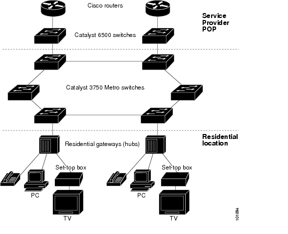
Multidwelling or Ethernet-to-the Subscriber Network
Figure 1-1 shows a Gigabit Ethernet ring for a residential location serving multitenant units using Catalyst 3750 Metro switches connected through 1000BASE-X SFP module ports. Catalyst 3750 Metro switches used as residential switches provide customers with high-speed connections to the service provider point-of presence (POP). Catalyst 2950 Long-Reach Ethernet (LRE) switches also can be used as residential switches for customers requiring connectivity through existing phone lines. The Catalyst 2950 LRE switches can then connect to another residential switch, such as a Catalyst 3750 Metro switch. For more information about the Catalyst LRE switches and LRE information, refer to the Catalyst 2950 LRE documentation set.
All ports on the residential switches (and Catalyst 2950 LRE switches if they are included) are configured as 802.1Q trunks with Private VLAN Edge (protected port) and STP root guard features enabled. The protected-port feature provides security and isolation between ports on the switch, ensuring that subscribers cannot view packets destined for other subscribers. STP root guard prevents unauthorized devices from becoming the STP root switch. All ports have IGMP snooping or CGMP enabled for multicast traffic management. ACLs on the uplink ports to the aggregating switches provide security and bandwidth management.
The aggregating switches and routers have HSRP enabled for load balancing and redundant connectivity to guarantee mission-critical traffic. This ensures connectivity to the Internet, WAN, and mission-critical network resources in case one of the routers or switches fails.
When an end station in one VLAN needs to communicate with an end station in another VLAN, a router or switch routes the traffic to the appropriate destination VLAN, providing inter-VLAN routing. VLAN access control lists (VLAN maps) provide intra-VLAN security and prevent unauthorized users from accessing critical pieces of the network.
In addition to inter-VLAN routing, the switch QoS mechanisms such as DSCP prioritize the different types of network traffic to deliver high-priority traffic in a predictable manner. If congestion occurs, QoS drops low-priority traffic to allow delivery of high-priority traffic.
The routers also provide firewall services, Network Address Translation (NAT) services, voice-over-IP (VoIP) gateway services, and WAN and Internet access.
Figure 1-1 Catalyst 3750 Metro Switches in a Multidwelling Configuration
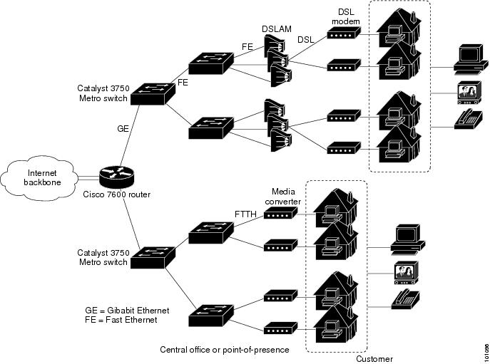
Ethernet Broadband Aggregation Network
Digital subscriber line (DSL) and fiber-to-the-house (FTTH) services provide high performance and increased bandwidth to the home or small-business customer for use in IP telephones, televisions, or PCs.
Catalyst 3750 Metro switch hierarchical QoS features allow service providers to support differentiated services with different levels of services for multiple customers. The configuration is applicable using DSL, sending packets through a digital subscriber line access multiplexer (DSLAM) and DSL modem to the residence, or using fiber-optic lines through a media converter to the residence. The end-user device can be a television, PC, or IP telephone.
Figure 1-2 Broadband Aggregation Network Using DSL or FTTH
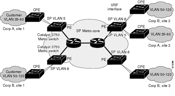
Layer 2 VPN Application
You can use Catalyst 3750 Metro switches to form Layer 2 VPNs so that customers at different locations can exchange information through a service-provider network, without requiring dedicated connections. IEEE 802.1Q and Layer 2 protocol tunneling are features designed for service providers who carry traffic of multiple customers across their networks and are required to maintain the VLAN and Layer 2 protocol configurations of each customer without impacting the traffic of other customers.
The Catalyst 3750 Metro switches are used as the provider edge (PE) switches at the both edges of the provider network connected to customer premises equipment (CPE) switches. The PE switches tag packets entering the service-provider network with the customer VLAN ID. VLAN mapping translates each customer VLAN ID to a service-provider VLAN ID for transport across the service-provider network. At the egress PE interface, the egress PE switch restores the original VLAN ID numbers for the customer's network.
The service provider can use 802.1Q tunneling or EoMPLS to provide Layer 2 VPN services. If the service-provider network is an MPLS cloud, and EoMPLS is configured as the point-to-point protocol, MPLS tags are added at the ingress PE ES port that connects to the MPLS network. The MPLS tags are removed at the ES port of the remote PE device.
See "Configuring IEEE 802.1Q and Layer 2 Protocol Tunneling," and "Configuring MPLS and EoMPLS," for more information on configuring these features.
Figure 1-3 Layer 2 VPN Configuration
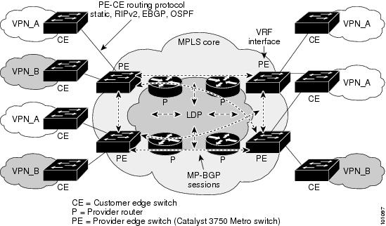
Layer 3 VPN Application
Layer 3 VPN services can use multi-VRF-CE or MPLS VPNs to deploy and administer scalable Layer 3 VPN services to business customers. A Layer 3 VPN is a secure IP-based network that shares resources on one or more physical networks. It contains geographically dispersed sites that can communicate securely over a shared backbone.
Figure 1-4 illustrates a typical MPLS VPN configuration. The CE devices (which can be Catalyst 3750 Metro switches or other Layer 3 switches) use a routing protocol, such as RIP, EBGP, OSPF, IS-IS, or static routing, to forward packets from customer VPNs to the Catalyst 3750 Metro PE devices at the edge of the MPLS network. The PE device is configured with multiprotocol BGP (MP-BGP), and a route distinguisher that is associated with the customer's VPN. The PE device converts this information to a VPN-IPv4 format and adds layer distribution protocol (LDP) labels to establish VPN routes.
VPN routes are distributed over the MPLS network using MP-BGP, which also distributes the labels associated with each VPN route. MPLS VPN depends on VPN routing and forwarding (VRF) support to isolate the routing domains from each other.
When an MPLS-VPN packet is received on a port, the CE switch looks up the labels in the routing table to determine what to do with the packet. A PE router binds a label to each customer prefix learned from a CE device and includes the label in the prefix that it advertises to other PE routers. When a PE router forwards a packet across the provider network, it labels the packet with the label learned from the destination PE router. When the destination PE router receives the labeled packet, it examines the label and uses it to direct the packet to the correct CE device.
Only the PE routers at each end of the MPLS network maintain the VPN routes for VPN members. Provider routers in the core network do not maintain the VPN routes. This ensures the security of customer VPNs and isolates them from other customer packets that are carried across the service-provider MPLS network.
Figure 1-4 MPLS VPN Configuration
See "Configuring MPLS and EoMPLS," for more information on configuring MPLS VPN.
Where to Go Next
Before configuring the switch, review these sections for startup information:
•
•