-
Catalyst 3550 Multilayer Switch Software Configuration Guide, 12.1(19)EA1
-
Index
-
Preface
-
Overview
-
Using the Command-Line Interface
-
Getting Started with CMS
-
Assigning the Switch IP Address and Default Gateway
-
Configuring IE2100 CNS Agents
-
Clustering Switches
-
Administering the Switch
-
Configuring Switch-Based Authentication
-
Configuring 802.1X Port-Based Authentication
-
Configuring Interface Characteristics
-
Configuring SmartPort Macros
-
Configuring VLANs
-
Configuring VTP
-
Configuring Voice VLAN
-
Configuring 802.1Q and Layer 2 Protocol Tunneling
-
Configuring STP
-
Configuring MSTP
-
Configuring Optional Spanning-Tree Features
-
Configuring DHCP Features
-
Configuring IGMP Snooping and MVR
-
Configuring Port-Based Traffic Control
-
Configuring CDP
-
Configuring UDLD
-
Configuring SPAN and RSPAN
-
Configuring RMON
-
Configuring System Message Logging
-
Configuring SNMP
-
Configuring Network Security with ACLs
-
Configuring QoS
-
Configuring EtherChannels
-
Configuring IP Unicast Routing
-
Configuring HSRP
-
Configuring Web Cache Services By Using WCCP
-
Configuring IP Multicast Routing
-
Configuring MSDP
-
Configuring Fallback Bridging
-
Troubleshooting
-
Supported MIBs
-
Working with the Cisco IOS File System, Configuration Files, and Software Images
-
Unsupported CLI Commands for Release 12.1(19)EA1
-
 Feedback
Table Of Contents
Configuring Interface Characteristics
Procedures for Configuring Interfaces
Configuring a Range of Interfaces
Configuring and Using Interface Range Macros
Configuring Ethernet Interfaces
Default Ethernet Interface Configuration
Configuring Interface Speed and Duplex Mode
Setting the Interface Speed and Duplex Parameters
Configuring Inline Power on the Catalyst 3550-24PWR Ports
Configuring IEEE 802.3X Flow Control
Adding a Description for an Interface
Configuring Layer 3 Interfaces
Monitoring and Maintaining the Interfaces
Monitoring Interface and Controller Status
Clearing and Resetting Interfaces and Counters
Shutting Down and Restarting the Interface
Configuring Interface Characteristics
This chapter describes the types of interfaces on a Catalyst 3550 switch and how to configure them. The chapter has these sections:
•
Understanding Interface Types
•
•
•
Note
Understanding Interface Types
This section describes the different types of interfaces supported by the switch with references to chapters that contain more detailed information about configuring these interface types. The rest of the chapter describes configuration procedures for physical interface characteristics.
These sections are included:
Port-Based VLANs
A VLAN is a switched network that is logically segmented by function, team, or application, without regard to the physical location of the users. For more information about VLANs, see "Configuring VLANs." Packets received on a port are forwarded only to ports that belong to the same VLAN as the receiving port. Network devices in different VLANs cannot communicate with one another without a Layer 3 device to route traffic between the VLANs.
VLAN partitions provide hard firewalls for traffic in the VLAN, and each VLAN has its own MAC address table. A VLAN comes into existence when a local port is configured to be associated with the VLAN, when the VLAN Trunking Protocol (VTP) learns of its existence from a neighbor on a trunk, or when a user creates a VLAN.
To configure normal-range VLANs (VLAN IDs 1 to 1005), use the vlan vlan-id global configuration command to enter config-vlan mode or the vlan database privileged EXEC command to enter VLAN configuration mode. The VLAN configurations for VLAN IDs 1 to 1005 are saved in the VLAN database. To configure extended-range VLANs (VLAN IDs 1006 to 4094), you must use config-vlan mode with VTP mode set to transparent. Extended-range VLANs are not added to the VLAN database. When VTP mode is transparent, the VTP and VLAN configuration is saved in the switch running configuration, and you can save it in the switch startup configuration file by entering the copy running-config startup-config privileged EXEC command.
Add ports to a VLAN by using the switchport interface configuration commands:
•
•
•
•
Switch Ports
Switch ports are Layer 2-only interfaces associated with a physical port. A switch port can be an access port, a trunk port, or a tunnel port. You can configure a port as an access port or trunk port or let the Dynamic Trunking Protocol (DTP) operate on a per-port basis to determine if a switch port should be an access port or a trunk port by negotiating with the port on the other end of the link. You must manually configure tunnel ports as part of an asymmetric link connected to an 802.1Q trunk port. Switch ports are used for managing the physical interface and associated Layer 2 protocols and do not handle routing or bridging.
Configure switch ports by using the switchport interface configuration commands. For detailed information about configuring access port and trunk port characteristics, see "Configuring VLANs." For more information about tunnel ports, see "Configuring 802.1Q and Layer 2 Protocol Tunneling."
Access Ports
An access port belongs to and carries the traffic of only one VLAN (unless it is configured as a voice VLAN port). Traffic is received and sent in native formats with no VLAN tagging. Traffic arriving on an access port is assumed to belong to the VLAN assigned to the port. If an access port receives a tagged packet (Inter-Switch Link [ISL] or 802.1Q tagged) for the VLAN assigned to the port, the packet is forwarded. If the port receives a tagged packet for another VLAN, the packet is dropped, the source address is not learned, and the frame is counted in the No destination statistic.
Two types of access ports are supported:
•
•
You can also configure an access port with an attached Cisco IP Phone to use one VLAN for voice traffic and another VLAN for data traffic from a device attached to the phone. For more information about voice VLAN ports, see "Configuring Voice VLAN."
Trunk Ports
A trunk port carries the traffic of multiple VLANs and by default is a member of all VLANs in the VLAN database. Two types of trunk ports are supported:
•
•
Although by default, a trunk port is a member of every VLAN known to the VTP, you can limit VLAN membership by configuring an allowed list of VLANs for each trunk port. The list of allowed VLANs does not affect any other port but the associated trunk port. By default, all possible VLANs (VLAN ID 1 to 4094) are in the allowed list. A trunk port can only become a member of a VLAN if VTP knows of the VLAN and the VLAN is in the enabled state. If VTP learns of a new, enabled VLAN and the VLAN is in the allowed list for a trunk port, the trunk port automatically becomes a member of that VLAN and traffic is forwarded to and from the trunk port for that VLAN. If VTP learns of a new, enabled VLAN that is not in the allowed list for a trunk port, the port does not become a member of the VLAN, and no traffic for the VLAN is forwarded to or from the port.
For more information about trunk ports, see "Configuring VLANs."
Tunnel Ports
Tunnel ports are used in 802.1Q tunneling to segregate the traffic of customers in a service provider network from other customers who appear to be on the same VLAN. You configure an asymmetric link from a tunnel port on a service provider edge switch to an 802.1Q trunk port on the customer switch. Packets entering the tunnel port on the edge switch, already 802.1Q-tagged with the customer VLANs, are encapsulated with another layer of 802.1Q tag (called the metro tag) containing a VLAN ID unique in the service provider network, for each customer. The double-tagged packets go through the service-provider network keeping the original customer VLANs separate from those of other customers. At the outbound interface, also a tunnel port, the metro tag is removed, and the original VLAN numbers from the customer network are retrieved.
Tunnel ports cannot be trunk ports or access ports and must belong to a VLAN unique for each customer.
For more information about tunnel ports, see "Configuring 802.1Q and Layer 2 Protocol Tunneling."
Switch Virtual Interfaces
A switch virtual interface (SVI) represents a VLAN of switch ports as one interface to the routing or bridging function in the system. Only one SVI can be associated with a VLAN, but you need to configure an SVI for a VLAN only when you wish to route between VLANs, fallback-bridge nonroutable protocols between VLANs, or to provide IP host connectivity to the switch. By default, an SVI is created for the default VLAN (VLAN 1) to permit remote switch administration. Additional SVIs must be explicitly configured. In Layer 2 mode, SVIs provide IP host connectivity only to the system; in Layer 3 mode, you can configure routing across SVIs.
SVIs are created the first time that you enter the vlan interface configuration command for a VLAN interface. The VLAN corresponds to the VLAN tag associated with data frames on an ISL or 802.1Q encapsulated trunk or the VLAN ID configured for an access port. Configure a VLAN interface for each VLAN for which you want to route traffic, and assign it an IP address. For more information, see the "Configuring IP Addressing on Layer 3 Interfaces" section.
Note
SVIs support routing protocols and bridging configurations. For more information about configuring IP routing, see "Configuring IP Unicast Routing," "Configuring IP Multicast Routing,"and "Configuring Fallback Bridging."
Note
Routed Ports
A routed port is a physical port that acts like a port on a router; it does not have to be connected to a router. A routed port is not associated with a particular VLAN, as is an access port. A routed port behaves like a regular router interface, except that it does not support VLAN subinterfaces. Routed ports can be configured with a Layer 3 routing protocol.
Note
Configure routed ports by putting the interface into Layer 3 mode with the no switchport interface configuration command. Then assign an IP address to the port, enable routing, and assign routing protocol characteristics by using the ip routing and router protocol global configuration commands.
Caution
The number of routed ports and SVIs that you can configure is not limited by software; however, the interrelationship between this number and the number of other features being configured might have an impact on CPU utilization because of hardware limitations. For more information about feature combinations, see the"Optimizing System Resources for User-Selected Features" section.
For more information about IP unicast and multicast routing and routing protocols, see "Configuring IP Unicast Routing" and "Configuring IP Multicast Routing."
EtherChannel Port Groups
EtherChannel port groups provide the ability to treat multiple switch ports as one switch port. These port groups act as a single logical port for high-bandwidth connections between switches or between switches and servers. An EtherChannel balances the traffic load across the links in the channel. If a link within the EtherChannel fails, traffic previously carried over the failed link changes to the remaining links. You can group multiple trunk ports into one logical trunk port, group multiple access ports into one logical access port, group multiple tunnel ports into one logical tunnel port, or group multiple routed ports into one logical routed port. Most protocols operate over either single ports or aggregated switch ports and do not recognize the physical ports within the port group. Exceptions are the DTP, the Cisco Discovery Protocol (CDP), and the Port Aggregation Protocol (PAgP), which operate only on physical ports.
When you configure an EtherChannel, you create a port-channel logical interface and assign an interface to the EtherChannel. For Layer 3 interfaces, you manually create the logical interface by using the interface port-channel global configuration command. For Layer 2 interfaces, the logical interface is dynamically created. For both Layer 3 and 2 interfaces, you manually assign an interface to the EtherChannel by using the channel-group interface configuration command. This command binds the physical and logical ports together. For more information, see "Configuring EtherChannels."
Connecting Interfaces
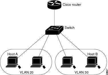
Devices within a single VLAN can communicate directly through any switch. Ports in different VLANs cannot exchange data without going through a routing device or routed interface.
With a standard Layer 2 switch, ports in different VLANs have to exchange information through a router. In the configuration shown in Figure 10-1, when Host A in VLAN 20 sends data to Host B in VLAN 30, it must go from Host A to the switch, to the router, back to the switch, and then to Host B.
Figure 10-1 Connecting VLANs with Layer 2 Switches
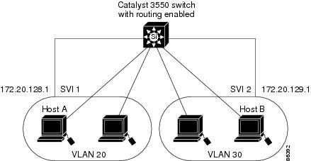
By using the Catalyst 3550 with routing enabled, when you configure VLAN 20 and VLAN 30 each with an SVI to which an IP address is assigned, packets can be sent from Host A to Host B directly through the Catalyst 3550 switch with no need for an external router (Figure 10-2).
Figure 10-2 Connecting VLANs with the Catalyst 3550 Multilayer Switch
The Catalyst 3550 switch with the enhanced multilayer software image supports two methods of forwarding traffic between interfaces: routing and fallback bridging; the standard software image supports only basic routing (static routing and RIP). Whenever possible, to maintain high performance, forwarding is done by switch hardware. However, only IP version 4 packets with Ethernet II encapsulation can be routed in hardware. All other types of traffic can be fallback bridged by hardware.
•
•
Using the Interface Command
The switch supports these interface types:
•
•
•
You can also configure a range of interfaces (see the "Configuring a Range of Interfaces" section).
To configure a physical interface (port), enter interface configuration mode, and specify the interface type, slot, and number.
•
•
•
You can identify physical interfaces by physically checking the interface location on the switch. You can also use the Cisco IOS show privileged EXEC commands to display information about a specific interface or all the interfaces on the switch. The remainder of this chapter primarily provides physical interface configuration procedures.
Procedures for Configuring Interfaces
These general instructions apply to all interface configuration processes.
Step 1
Switch# configure terminalEnter configuration commands, one per line. End with CNTL/Z.Switch(config)#Step 2
Switch(config)# interface gigabitethernet0/1Switch(config-if)#
Note
Step 3
You can also configure a range of interfaces by using the interface range or interface range macro global configuration commands. Interfaces configured in a range must be the same type and must be configured with the same feature options.
Step 4
Enter the show interfaces privileged EXEC command to see a list of all interfaces on or configured for the switch. A report is provided for each interface that the device supports or for the specified interface:
Configuring a Range of Interfaces
You can use the interface range global configuration command to configure multiple interfaces with the same configuration parameters. When you enter the interface range configuration mode, all command parameters that you enter are attributed to all interfaces within that range until you exit this mode.
Beginning in privileged EXEC mode, follow these steps to configure a range of interfaces with the same parameters:
Step 1
configure terminal
Enter global configuration mode.
Step 2
interface range {port-range | macro macro_name}
Enter interface range configuration mode by entering the range of interfaces (VLANs or physical ports) to be configured.
•
•
•
•
Step 3
You can now use the normal configuration commands to apply the configuration parameters to all interfaces in the range.
Step 4
end
Return to privileged EXEC mode.
Step 5
show interfaces [interface-id]
Verify the configuration of the interfaces in the range.
Step 6
copy running-config startup-config
(Optional) Save your entries in the configuration file.
When using the interface range global configuration command, note these guidelines:
•
–
–
–
–
•
•
•
This example shows how to use the interface range global configuration command to enable Fast Ethernet interfaces 0/1 to 0/5:
Switch# configure terminalSwitch(config)# interface range fastethernet0/1 - 5Switch(config-if-range)# no shutdownSwitch(config-if-range)#*Oct 6 08:24:35: %LINK-3-UPDOWN: Interface FastEthernet0/1, changed state to up*Oct 6 08:24:35: %LINK-3-UPDOWN: Interface FastEthernet0/2, changed state to up*Oct 6 08:24:35: %LINK-3-UPDOWN: Interface FastEthernet0/3, changed state to up*Oct 6 08:24:35: %LINK-3-UPDOWN: Interface FastEthernet0/4, changed state to up*Oct 6 08:24:35: %LINK-3-UPDOWN: Interface FastEthernet0/5, changed state to up*Oct 6 08:24:36: %LINEPROTO-5-UPDOWN: Line protocol on Interface FastEthernet0/05, changed state to up*Oct 6 08:24:36: %LINEPROTO-5-UPDOWN: Line protocol on Interface FastEthernet0/3, changed state to up*Oct 6 08:24:36: %LINEPROTO-5-UPDOWN: Line protocol on Interface FastEthernet0/4, changed state to upThis example shows how to use a comma to add different interface type strings to the range to enable all Fast Ethernet interfaces in the range 0/1 to 0/3 and Gigabit Ethernet interfaces 0/1 and 0/2:
Switch# configure terminalSwitch(config)# interface range fastethernet0/1 - 3, gigabitethernet0/1 - 2Switch(config-if-range)# no shutdownSwitch(config-if-range)#*Oct 6 08:29:28: %LINK-3-UPDOWN: Interface FastEthernet0/1, changed state to up*Oct 6 08:29:28: %LINK-3-UPDOWN: Interface FastEthernet0/2, changed state to up*Oct 6 08:29:28: %LINK-3-UPDOWN: Interface FastEthernet0/3, changed state to up*Oct 6 08:29:28: %LINK-3-UPDOWN: Interface GigabitEthernet0/1, changed state to up*Oct 6 08:29:28: %LINK-3-UPDOWN: Interface GigabitEthernet0/2, changed state to up*Oct 6 08:29:29: %LINEPROTO-5-UPDOWN: Line protocol on Interface GigabitEthernet0/ 1, changed state to up*Oct 6 08:29:29: %LINEPROTO-5-UPDOWN: Line protocol on Interface FastEthernet0/ 2, changed state to up*Oct 6 08:29:29: %LINEPROTO-5-UPDOWN: Line protocol on Interface FastEthernet0/ 3, changed state to upIf you enter multiple configuration commands while you are in interface range mode, each command is executed as it is entered. The commands are not batched together and executed after you exit interface range mode. If you exit interface range configuration mode while the commands are being executed, some commands might not be executed on all interfaces in the range. Wait until the command prompt reappears before exiting interface range configuration mode.
Configuring and Using Interface Range Macros
You can create an interface range macro to automatically select a range of interfaces for configuration. Before you can use the macro keyword in the interface range macro global configuration command string, you must use the define interface-range global configuration command to define the macro.
Beginning in privileged EXEC mode, follow these steps to define an interface range macro:
Use the no define interface-range macro_name global configuration command to delete a macro.
When using the define interface-range global configuration command, note these guidelines:
•
–
–
–
–
•
•
•
This example shows how to define an interface-range macro named enet_list to select Fast Ethernet ports 1 to 4 and to verify the macro configuration:
Switch# configure terminalSwitch(config)# define interface-range enet_list fastethernet0/1 - 4Switch(config)# endSwitch# show running-config | include definedefine interface-range enet_list FastEthernet0/1 - 4This example shows how to create a multiple-interface macro named macro1:
Switch# configure terminalSwitch(config)# define interface-range macro1 gigabitethernet0/1 - 2, fastethernet0/5 - 7Switch(config)# endSwitch#This example shows how to enter interface range configuration mode for the interface-range macro enet_list:
Switch# configure terminalSwitch(config)# interface range macro enet_listSwitch(config-if-range)#This example shows how to delete the interface-range macro enet_list and to verify that it has been deleted.
Switch# configure terminalSwitch(config)# no define interface-range enet_listSwitch# show run | include defineConfiguring Ethernet Interfaces
These sections describe the default interface configuration and the optional features that you can configure on most physical interfaces:
•
•
•
•
Caution
Default Ethernet Interface Configuration
Table 10-1 shows the Ethernet interface default configuration. For more details on the VLAN parameters listed in the table, see "Configuring VLANs." For details on controlling traffic to the port, see "Configuring Port-Based Traffic Control."
Table 10-1 Default Ethernet Interface Configuration
Operating mode
Layer 2 or switching mode (switchport command).
Allowed VLAN range
VLANs 1 - 4094.
Default VLAN (for access ports)
VLAN 1.
Native VLAN (for 802.1Q trunks)
VLAN 1.
VLAN trunking
Switchport mode dynamic desirable (supports DTP).
Port enable state
All ports are enabled.
Port description
None defined.
Speed
Autonegotiate.
Duplex mode
Autonegotiate.
Flow control
Flow control is set to off for receive and desired for send for Gigabit Ethernet ports. For 10/100 Mb/s ports, send is always off.
EtherChannel (PAgP)
Disabled on all Ethernet ports. See "Configuring EtherChannels."
Port blocking (unknown multicast and unknown unicast traffic)
Disabled (not blocked). See the "Configuring Port Blocking" section.
Broadcast, multicast, and unicast storm control
Disabled. See the "Default Storm Control Configuration" section.
Protected port
Disabled. See the "Configuring Protected Ports" section.
Port security
Disabled. See the "Default Port Security Configuration" section.
Port Fast
Disabled.
Configuring Interface Speed and Duplex Mode
Ethernet interfaces on the switch operate in 10, 100, or 1000 Mbps and in either full- or half-duplex mode. In full-duplex mode, two stations can send and receive at the same time. When packets can flow in both directions simultaneously, effective Ethernet bandwidth doubles to 20 Mbps for 10-Mbps interfaces, to 200 Mbps for Fast Ethernet interfaces, and to 2 Gbps for Gigabit interfaces. Full-duplex communication is often an effective solution to collisions, which are major constrictions in Ethernet networks. Normally, 10-Mbps ports operate in half-duplex mode, which means that stations can either receive or send.
You can configure interface speed on Fast Ethernet (10/100-Mbps) and Gigabit Ethernet (10/100/1000-Mbps) interfaces; you cannot configure speed on Gigabit Interface Converter (GBIC) interfaces. You can configure duplex mode on any Fast Ethernet or Gigabit Ethernet interfaces that are not set to autonegotiate; you cannot configure duplex mode on GBIC interfaces.
Note
These sections describe how to configure the interface speed and duplex mode:
•
Configuration Guidelines
When configuring an interface speed and duplex mode, note these guidelines:
•
•
•
•
•
Caution
Setting the Interface Speed and Duplex Parameters
Beginning in privileged EXEC mode, follow these steps to set the speed and duplex mode for a physical interface:
Use the no speed and no duplex interface configuration commands to return the interface to the default speed and duplex settings (autonegotiate). To return all interface settings to the defaults, use the default interface interface-id interface configuration command.
This example shows how to set the interface speed to 10 Mbps and the duplex mode to half on FastEthernet interface 0/3:
Switch# configure terminalSwitch(config)# interface fastethernet0/3Switch(config-if)# speed 10Switch(config-if)# duplex halfConfiguring Inline Power on the Catalyst 3550-24PWR Ports
The Catalyst 3550-24PWR switch automatically supplies inline power to connected Cisco IP Phones, Cisco Aironet Access Points, and IEEE Power Devices if it senses no power on the circuit. If there is power on the circuit, the switch does not supply it. You can also configure the Catalyst 3550-24PWR switch to never supply power to these devices and to disable the inline-power detection.
For certain IEEE Power Devices that require multiple reloads during initialization, you can set a delay shutdown time to configure the switch to continue providing power during initialization. For more information about configuring a delay shutdown time, refer to the command reference for this release.
Note
Cisco IP Phones and access points can also be connected to an AC power source and supply their own power.
For information about configuring a switch port to forward IP voice traffic to and from connected Cisco IP Phones, see the "Configuring a Port to Connect to a Cisco 7960 IP Phone" section.
Beginning in privileged EXEC mode, follow these steps to enable the inline-power on an inline-power capable port:
To permanently disable inline-power on a port, use the power inline never interface configuration command.
Configuring IEEE 802.3X Flow Control
Flow control enables connected Ethernet ports to control traffic rates during congestion by allowing congested nodes to pause link operation at the other end. If one port experiences congestion and cannot receive any more traffic, it notifies the other port to stop sending until the condition clears. When the local device detects any congestion at its end, it can notify the link partner or the remote device of the congestion by sending a pause frame. Upon receipt of a pause frame, the remote device stops sending any data packets, which prevents any loss of data packets during the congestion period.
Note
Flow control can be implemented in two forms, symmetric and asymmetric. The symmetric implementation is suitable for point-to-point links, and asymmetric is suitable for hub-to-end node connections, where it is desirable for the hub to pause the end system, but not vice-versa. You use the flowcontrol interface configuration command to set the interface's ability to receive and send pause frames to on, off, or desired. The default state for Gigabit Ethernet ports is receive off and send desired. The default state for Fast Ethernet ports is receive off and send off.
Note
These rules apply to flow control settings on the device:
•
•
•
•
•
•
Note
Beginning in privileged EXEC mode, follow these steps to configure flow control on an interface:
To disable flow control, use the flowcontrol receive off and flowcontrol send off interface configuration commands.
This example shows how to turn off all flow control on Gigabit Ethernet interface 0/1:
Switch# configure terminalSwitch(config)# interface gigabitethernet0/1Switch(config-if)# flowcontrol receive offSwitch(config-if)# flowcontrol send offSwitch(config-if)# endAdding a Description for an Interface
You can add a description about an interface to help you remember its function. The description appears in the output of these commands: show configuration, show running-config, and show interfaces.
Beginning in privileged EXEC mode, follow these steps to add a description for an interface:
Use the no description interface configuration command to delete the description.
This example shows how to add a description on Fast Ethernet interface 0/4 and to verify the description:
Switch# config terminalEnter configuration commands, one per line. End with CNTL/Z.Switch(config)# interface fastethernet0/4Switch(config-if)# description Connects to MarketingSwitch(config-if)# endSwitch# show interfaces fastethernet0/4 descriptionInterface Status Protocol DescriptionFa0/4 up down Connects to MarketingConfiguring Layer 3 Interfaces
The Catalyst 3550 supports three types of Layer 3 interfaces:
•
Note
•
EtherChannel port interfaces are described in "Configuring EtherChannels."
•
Note
All Layer 3 interfaces require an IP address to route traffic. The following procedure shows how to configure an interface as a Layer 3 interface and how to assign an IP address to an interface.
Note
Beginning in privileged EXEC mode, follow these steps to configure a Layer 3 interface:
To remove an IP address from an interface, use the no ip address interface configuration command.
This example shows how to configure an interface as a routed port and to assign it an IP address:
Switch# configure terminalEnter configuration commands, one per line. End with CNTL/Z.Switch(config)# interface gigabitethernet0/2Switch(config-if)# no switchportSwitch(config-if)# ip address 192.20.135.21 255.255.255.0Switch(config-if)# no shutdownSwitch(config-if)# endThis is an example of output from the show ip interface privileged EXEC command for the interface:
Switch# show ip interface gigabitethernet0/2GigabitEthernet0/2 is up, line protocol is upInternet address is 192.20.135.21/24Broadcast address is 255.255.255.255Address determined by setup commandMTU is 1500 bytesHelper address is not setDirected broadcast forwarding is disabled<output truncated>Monitoring and Maintaining the Interfaces
You can perform the tasks in these sections to monitor and maintain interfaces:
•
•
•
Monitoring Interface and Controller Status
Commands entered at the privileged EXEC prompt display information about the interface, including the version of the software and the hardware, the controller status, and statistics about the interfaces. Table 10-2 lists some of these interface monitoring commands. (You can display the full list of show commands by using the show ? command at the privileged EXEC prompt.) These commands are fully described in the Cisco IOS Interface Command Reference for Release 12.1.
This example shows how to display the status of all interfaces:
Switch# show interfaces statusPort Name Status Vlan Duplex Speed TypeGi0/1 connected routed a-full a-100 10/100/1000BaseTXGi0/2 wce server 20.20.2 disabled routed auto auto 10/100/1000Base TXGi0/3 ip wccp web-cache notconnect routed auto auto 10/100/1000Base TXGi0/4 notconnect routed auto auto 10/100/1000Base TXGi0/5 notconnect routed auto auto 10/100/1000Base TXGi0/6 disabled routed auto auto 10/100/1000Base TXGi0/7 disabled routed auto auto 10/100/1000Base TXGi0/8 disabled routed auto 100 10/100/1000Base TXGi0/9 notconnect routed auto auto 10/100/1000Base TXGi0/10 notconnect routed auto auto 10/100/1000Base TXGi0/11 disabled routed auto auto unknownGi0/12 notconnect routed auto auto unknownThis example shows how to display the status of switching port Fast Ethernet 0/1:
Switch# show interfaces fastethernet 0/1 switchportName: Fa0/1Switchport: EnabledAdministrative Mode: static accessOperational Mode: downAdministrative Trunking Encapsulation: dot1qNegotiation of Trunking: OffAccess Mode VLAN: 1 (default)Trunking Native Mode VLAN: 1 (default)Trunking VLANs Enabled: ALLPruning VLANs Enabled: 2-1001Protected: falseUnknown unicast blocked: disabledUnknown multicast blocked: disabledVoice VLAN: dot1p (Inactive)Appliance trust: 5This example shows how to display the running configuration of Fast Ethernet interface 0/2:
Switch# show running-config interface fastethernet0/2Building configuration...Current configuration : 131 bytes!interface FastEthernet0/2switchport mode accessswitchport protectedno ip addressmls qos cos 7mls qos cos overrideendFor additional examples of the show interfaces privileged EXEC command, refer to the command reference for this release.
Clearing and Resetting Interfaces and Counters
Table 10-3 lists the privileged EXEC mode clear commands that you can use to clear counters and reset interfaces.
To clear the interface counters shown by the show interfaces privileged EXEC command, use the clear counters privileged EXEC command. The clear counters command clears all current interface counters from the interface unless optional arguments are specified to clear only a specific interface type from a specific interface number.
Note
This example shows how to clear and reset the counters on Fast Ethernet interface 0/5:
Switch# clear counters fastethernet0/5Clear "show interface" counters on this interface [confirm] ySwitch#*Sep 30 08:42:55: %CLEAR-5-COUNTERS: Clear counter on interface FastEthernet0/5by vty1 (171.69.115.10)Use the clear interface or clear line privileged EXEC command to clear and reset an interface or serial line. Under most circumstances, you do not need to clear the hardware logic on interfaces or serial lines.
This example shows how to clear and reset Fast Ethernet interface 0/5:
Switch# clear interface fastethernet0/5Shutting Down and Restarting the Interface
Shutting down an interface disables all functions on the specified interface and marks the interface as unavailable on all monitoring command displays. This information is communicated to other network servers through all dynamic routing protocols. The interface is not mentioned in any routing updates.
Beginning in privileged EXEC mode, follow these steps to shut down an interface:
Use the no shutdown interface configuration command to restart the interface.
This example shows how to shut down Fast Ethernet interface 0/5:
Switch# configure terminalSwitch(config)# interface fastethernet0/5Switch(config-if)# shutdownSwitch(config-if)#*Sep 30 08:33:47: %LINK-5-CHANGED: Interface FastEthernet0/5, changed state to a administratively downThis example shows how to re-enable Fast Ethernet interface 0/5:
Switch# configure terminalSwitch(config)# interface fastethernet0/5Switch(config-if)# no shutdownSwitch(config-if)#*Sep 30 08:36:00: %LINK-3-UPDOWN: Interface FastEthernet0/5, changed state to upTo verify that an interface is disabled, enter the show interfaces privileged EXEC command. A disabled interface is shown as administratively down in the show interface command display.