-
Cisco MDS 9000 Family Storage Media Encryption Configuration Guide, Release 5.x
-
Index
-
New and Changed Information
-
Preface
-
Cisco SME Overview
-
Cisco SME Getting Started
-
Cisco SME Interface Configuration
-
Cisco SME Cluster Management
-
Cisco SME Tape Management
-
Cisco SME Disk Management
-
Cisco SME Key Management
-
Provisioning Certificates
-
RSA Key Manager and Cisco SME
-
Cisco SME Best Practices
-
Cisco SME Troubleshooting
-
Cisco SME CLI Commands
-
Disaster Recovery
-
Offline Data Restore Tool
-
Database Backup and Restore
-
Planning for Cisco SME Installation
-
Migrating Cisco SME Database Tables
-
 Feedback
Table Of Contents
Information About SME Disk Management
Manage Key Change Operations in DCNM for DKR
Recovering SME Disk when Data Preparation Fails
Replacing an SME Enabled MDS Switch
Guidelines and Limitations for DKR
Replication or Mirroring Requirements
Managing Key Change Operations in Cisco DCNM for DKR
Configuring SME Disk Management Using the CLI
Adding SME Nodes to the Cluster
Adding SME Encryption Engine to the Cluster
Adding a Disk to the Disk Group
Enabling Encryption on the SME Disk with Data Preparation
Configuring SME Disk Management Using the GUI
Converting Disks to Signature Mode
Verifying Signatures for Disks
Configuring and Discovering Disk Paths
Suspending and Resuming the Configured Disk
Suspending the Configured Disk
Managing Disk Encryption on SME Disks
Performing Data Preparation on the Disk for Converting Clear Data to Encrypted Data
Performing Data Preparation on the Disk for Converting Encrypted Data to Clear Data
Recovering a Disk to Clear Status
Recovering a Disk to Encrypted Status
Recovering a Disk Using Metadata Signature
Recovering a Disk from Key Manager
Performing Disk Encryption to Convert the Disk Status from Clear to Crypto
Performing Disk Encryption to Convert the Disk Status from Crypto to Clear
Exporting Keys for Single Disk
Exporting Keys for Multiple Disks
Importing Keys to a Single Disk or to a Disk Set
Restoring an Encrypted Disk from a Deactivated Key
Restoring a Deactivated Key Using the Select Key Option
Restoring a Deactivated Key Using the Input GUID Option
Enabling or Disabling Disk Key Replication
Removing or Deleting Replication Relationships
Performing the Switchover Operation
Configuring Key Management Operations
Verifying the SME Disk Management Configuration
Monitoring SME Disk Management
Viewing Signature Mode Clusters
Viewing SME Disk Information Using the CLI
Feature History for SME Disk Management
Configuring SME Disks
This chapter contains information about managing disks using SME, referred to as SME Disk management.
Note
Read all of the Cautions carefully while configuring SME Disks.
This chapter includes the following topics:
•
•
•
•
•
•
Information About SME Disk Management
SME Disk management includes the following topics:
•
•
SME Disk Architecture
The SME Disk feature encrypts the data contained in a disk.
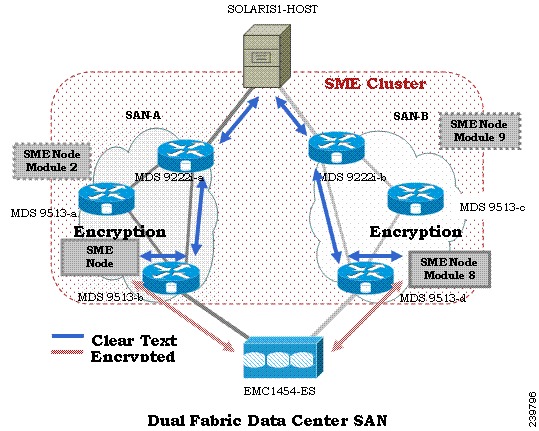
The software architecture for the SME Disk is similar to the existing SME infrastructure that supports the SME tape. Disk support has been added to the existing SME architecture from MDS NX-OS Release 5.2.1. Figure 6-1 depicts a typical dual-fabric production data center. The SME disk functionality is provided on the following Cisco MDS hardware:
•
•
•
Figure 6-1 shows the SME Disk architecture.
Figure 6-1 SME Disk Architecture
In the figure, a switch is termed as an SME node. A module has one or more interfaces that support SME. The SME nodes encrypt and decrypt the traffic flowing between the host and the storage. The Fibre Channel traffic to be encrypted or decrypted is directed to the SME node through the FC-Redirect feature of the SAN. For example, the SSN-16 can support 4 SME interfaces and the MSM-18/4 supports 1 SME interface.
SME Disk functionality works in the dual-fabric topology, where it performs encryption and decryption on all the paths present between the host and the storage.
Caution
SME Disk needs to manage all the paths to the disk in both the fabrics. An SME cluster provides this functionality. An SME cluster consists of a collection of SME nodes. Any SME node that fails in a cluster triggers another node in the same cluster to take control of the encryption and/or decryption activity.
The disk on which the SME Disk provides the encryption and/or decryption functionality can be the one without any existing data or the one with existing data. If the disk has existing data, the existing data needs to be encrypted. The process of converting the existing clear data to encrypted data is termed as data preparation.
Data preparation can be performed in offline mode. In the offline data preparation mode, the application on the host accessing the disk is quiesced and no I/Os are sent to the disk. SME Disk functionality also ensures that if any host tries to read or write the data from or into the disk, the particular I/O is failed back to the host.
In the Online Mode, the application on the host can continue to perform I/O on the disk while SME is converting the existing data on the disk from clear text to encrypted text.
The disk is uniquely identified in configuration by the cluster name, disk group name, and disk name.
For the purpose of encryption or decryption, the SME Disk requires encryption keys. For every encrypted disk, a key is generated. The SME's existing Key Management Center (KMC) infrastructure is used for SME disk key management. Keys for each disk are generated by the Storage Media Encryption coprocessor and are stored in the SME Key Management Center.
Caution
For Release 5.2.1, the maximum supported disk size is one block less than two terabyte (TB). The maximum LBA is 0xFFFFFFFE.
From Release 5.2.6, the supported disk size for signature and nonsignature mode clusters is greater than two TB.
SME Disk only supports disk block size of 512 bytes.
For Release 5.2.1, SME Disk does not support online conversion of existing clear data on the disk to encrypted data.
Replication
There are two kinds of replication:
•
•
–
–
Snapshot
Snapshots are point-in-time copies that can be created instantly for a source disk. Once a snapshot is created any writes to the source disk will result in the previous data to be saved elsewhere before modification. This allows the disk array to present a specific point-in-time copy of the data of the source disk.
Managing Replication with SME
SME supports replication through Disk key replication (DKR). DKR simplifies the key management of the source and destination disk by automating the propagation of the source disk key to destination disk. SME Disk Clusters are of two modes:
•
•
Replication management is the same for both the cluster modes. Replication management consists of following steps:
•
•
Note
Manage Key Change Operations in DCNM for DKR
Key change operations involve the following:
•
•
–
–
Note
Managing Snapshots in SME
This section describes how to manage snapshots of crypto disks. Snapshot management is different for signature and non-signature clusters.
To manage crypto snapshots that are discovered by a same host through the same SME cluster as the source disk, then follow the below procedure:
Step 1
Step 2
Step 3
Step 4
To manage snapshots that are being discovered by a different host through a differnt SME cluster from the source, use DKR and follow the below procedure:
Step 1
Step 2
Step 3
Step 4
Step 5
Note
Cluster Support
For Release 5.2.1, the switch can support up to two SME clusters. The following prerequisites must be met for supporting multiple clusters. If these prerequisites are not met data loss can occur.
•
•
•
–
–
–
•
•
•
From MDS Release 5.2(6), SME Disk can write a signature to the media to identify the disk as a crypto disk. These SME clusters are called signature clusters. Nonsignature clusters are SME Disks that do not write a signature on the media to identify crypto on the disk.
Data Preparation
Data preparation is a process that converts the clear data on the disk to encrypted data and vice versa. When the SME Disk feature is enabled on an existing disk containing clear data, the existing clear data needs to be converted to encrypted data. The process can be done in two ways:
•
•
Note
When the SME Disk feature is enabled on a new disk that does not contain prior data, the host I/Os read/write is decrypted or encrypted using a key. This encryption process is transparent to the application. For these disks, the data preparation process is not required.
Note
For disks requiring data preparation, the user must have backed up data before starting conversion of clear data to encrypted data.
In an SME cluster, there can be multiple SME nodes handling the ITLs associated with a particular crypto disk. The multiple SME nodes encrypt or decrypt data written to or read from the crypto disk. However, the responsibility of the data preparation or rekeying for a crypto disk is assigned to one SME node which is the data preparation node. The cluster master handles the data preparation node based on the following:
•
•
•
For signature mode, when converting a clear disk to crypto disk, the administrator must ensure that the reserved space of 64 MB at the end of the disk is available on the SME disk.
Note
Recovering SME Disk when Data Preparation Fails
When data preparation fails, SME Disk puts the disk in a failed state. The disk is not accessible to hosts and all paths of the disk are put in I/O reject state ( reject all host I/Os state). To recover the disk from the failed state, follow these steps:
Step 1
Step 2
In the Signature mode, the disk can be recovered by using the signature information on the media.
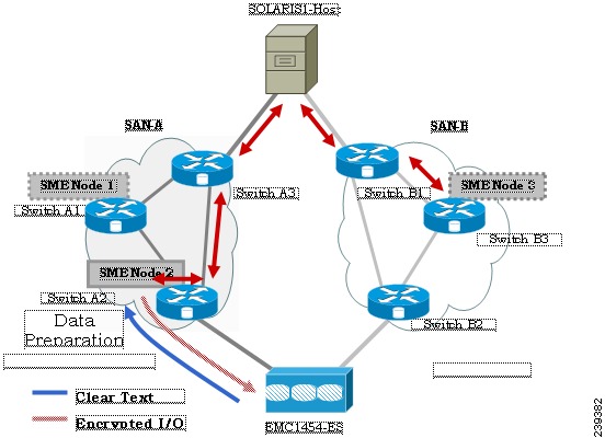
Offline Data Preparation
Offline data preparation is performed when the applications running on the host is not accessing data from the disk that is undergoing data preparation.
Figure 6-2 shows the SME Disk offline data preparation architecture.
Figure 6-2 SME Disk Offline Data Preparation Architecture
The offline data preparation involves the following actions:
•
•
•
Caution
Caution
Caution
•
•
Online Data Preparation
Online data preparation is performed when the applications on the host are accessing the data on the crypto disk. The server read or write I/Os are decrypted or encrypted by the SME nodes while the data preparation process is going on.
Note
Rekeying
Once the data on the disk is encrypted, the key associated with the encrypted data has to be changed for security reasons. The change policy is organization specific. The process of changing the key associated with the encrypted data for a disk from an old key to a new key is referred to as the rekey process.
Rekeying is a special function of the data preparation operation where the currently encrypted contents of the disk is read, decrypted using the current (old) key, encrypted with a new key, and written back to the disk.
Note
Replacing an SME Enabled MDS Switch
The steps to replace an MDS Switch acting as a node in one or more SME clusters depends on your current topology and configuration.
Multi-node Cluster
If the MDS switch you want to replace is the master node in one or more SME Clusters, you must first fail the master node and then remove the failed master node.
If the MDS switch you want to replace is a non-master node in a multi-node SME cluster, you must remove the SME interfaces (if any) and the node from the clusters using the DCNM SME management UI. For more infomation, see "Removing (Unbinding) SME Interfaces from a SME Cluster" section and "Deleting Switches From a SME Cluster" section.
Single-node Cluster
If the MDS switch you want replace is the only node in an SME Cluster, the operation is completely destructive to the SME Cluster. Follow the procedure under Appendix M, "Disaster Recovery in SME." to build a new SME Cluster on the new switch.
Turning Off Encryption
If you disable encryption in the signature mode, the host can view the exact size of the disk. The exact size of the disk is 64 MB more than the size of the disk seen during encryption.
Snapshot Support
There are two types of snapshot supported:
•
•
SME Disk Key Management
SME disk uses a two-level key hierarchy. An SME cluster consists of various disks that are grouped functionally into disk groups. The following is the key hierarchy:
•
•
Keys are identified using a Globally Unique Identifier (GUID) and disk keys are stored in the Cisco Key Management Center (KMC). These disk keys are encrypted using the master key.
Key Generation
The secure keys are generated for each SME disk in the cluster in the SME node in a cryptographic way. Random key numbers are generated with the FIPS random-number generation. The key size used is 256 bits.
A new key can be generated for each SME disk that is enabled. Keys also can be imported from a key file. Keys can also be replicated using the disk key replication feature.
Disk States
These types of disk states are available:
•
•
•
•
•
•
•
MKR fails when the disks are in the following states:
•
•
•
•
•
•
•
•
•
•
Note
Cisco KMC
The Cisco KMC is the centralized key management system that stores the key database for active and archived keys required for the encryption and decryption in the SME disk.
Each SME disk can have zero or one active key and zero or more archived keys.
Each key entry consists of the following:
•
•
•
•
SME cluster will contact and verify and update the CKMC during configuration changes.
CKMC provides the following features:
•
•
•
For more information on the security modes and key management settings, see the "Configuring SME Key Management" section
Cisco KMC supports SME disk-related operations. KMC operations include the following topics:
Archiving Clusters
Archiving deletes the cluster from the switch and it retains the keys in the Cisco KMC.
Purging Disks or Disk Groups
When storage arrays are decommissioned either due to lease expiration or upgrade, the keys associated with the disks can be purged. Purging keys can be done either at the disk level or at the disk group level. By deleting an active disk group, all the keys are archived. By deleting an archived disk group, all the keys are purged.
Caution
Rekeying
Data in the disk and disk group can be rekeyed either periodically for better security or on-demand when the key security has been compromised.
Note
The rekey operation at an individual disk level generates a new key for the disk and archives the old key. A data preparation operation is triggered to decrypt the data using old key, encrypt the data with the new key, and write it back to the disk.
The rekey operation performed at a disk group level on all the disks or a subset of disks in the disk group. KMC maintains a history of keys for all of the disks.
Accounting
Cisco KMC maintains an accounting log to record all the key-related operations, their results, and other related information. The view provides support to filter the log records based on the patterns. For more information, see Cisco KMC.
Quorum Disk
A quorum has to be present for a cluster to be functional as a cluster is a group of servers. A quorum is defined as N/2 + 1 servers in the cluster are up and running. N is the total number of servers in the cluster. To avoid a split-brain scenario for a cluster with an even number of servers, in the case where half of the members of the cluster lose communication with the other half of the members of the cluster, a quorum disk is used to determine which partition has the quorum for remaining in the cluster.
Because a server cluster has to be functional even when an SME cluster fails, it is important that the quorum disk not be configured as a crypto disk.
Data Replication
Replication is a disk array based technology where the disk array automatically duplicates data from one LUN to another.
Data replication relationship is of two types:
•
•
Remote replication involves in moving of data on primary storage arrays over WAN links to secondary storage arrays on secondary sites. Remote replication protects data loss in case of primary site failure or a geographical disaster.
SME does not perform data replication. SME is designed to support other third-party data replication solutions.
SME Disk Key Replication
The SME Disk Key Replication (DKR) feature manages key replication in support of third-party data mirroring solutions. The DKR feature supports the following:
•
•
Note
Note
The source and the destination disk can be in three stable states: clear, crypto, and failed. When a disk key replication relationship is synchronized, both the state and the active crypto key of the source disk are replicated to the destination disk.
The DKR feature is maintained by DCNM-SAN and all SME key modification operations for disks using DKR must be done through DCNM-SAN.
Caution
Note
Note
Prerequisites for DKR
DKR has the following prerequisites:
•
•
Caution
Guidelines and Limitations for DKR
The following are the guidelines and limitations for disk replication support:
•
•
Caution
Replication or Mirroring Requirements
The following are the requirements for replication or mirroring:
•
•
•
DKR Features
DKR provides the following key features:
•
•
•
DKR Relationships
DKR relationships are created through the DKR map file. Specify the source and destination disks that are in a DKR relationship, which allows you to input a large number of entries in a single operation. DKR relationships can be set up in two ways:
•
DKR Mapping File
You can populate the DKR database by giving DCNM-SAN a map file that contains the replication and snapshot relationships. Each DKR relationship consists of a source and destination disk.
The disk can be identified in the following format:
<?xml version="1.0" encoding="UTF-8"?><SME_DKR xmlns:xsi="http://www.w3.org/2001/XMLSchema-instance" xsi:noNamespaceSchemaLocation="DKR.xsd"><Version>Version</Version><Options>SME_DKR_NONE</Options><Relations><Type>SME_DKR_MIRROR</Type><Source><Label>grp-1</Label><Cluster_Name>source-1</Cluster_Name><Disk_Group_Name>primary-cx400</Disk_Group_Name><Disk_Name>pry0</Disk_Name><Identifier><VPW><Vendor>DGC </Vendor><Product>VRAID </Product><WWN>600601609bc12a008ca7298a9c44e011</WWN></VPW></Identifier></Source><Destination><Label>grp-2emote</Label><Cluster_Name>destination-1</Cluster_Name><Disk_Group_Name>secondary-cx400</Disk_Group_Name><Disk_Name>sec0</Disk_Name><Identifier><VPW><Vendor>DGC </Vendor><Product>VRAID </Product><WWN>600601600e602a00b461b7289b44e011</WWN></VPW></Identifier></Destination></Relations></SME_DKR>
Note
ISSU with SME Disk
In-Service Software Upgrade (ISSU) has the following requirements:
•
•
•
•
Note
When upgrading from Release 5.2.1 to Release 5.2.6, the clusters have to be in the nonsignature mode and when downgrading from Release 5.2.6 to Release 5.2.1, signature clusters have to be deleted.
Managing Key Change Operations in Cisco DCNM for DKR
The following are the two key change operations:
•
•
–
–
Once data preparation is complete and verified for data integrity, perform the following:
–
–
Caution
Read-Only Disks
Read-only disks allows the host to read the contents of a disk in a failed state by specifying an encryption key. This is a solution to recover the contents of a disk. When there is an situation where the possible set of keys to a disk is known, this mode can be used to try each of the possible keys to find the correct key to read the contents of the disk. This mode is not expected to be used in the normal configuration or normal recovery procedures that have been discussed in this document.
To recover the data using the read-only mode, perform the following steps:
Step 1
Once you get the correct key, you can recover the disk using the recovery wizard.
Step 2
Write Signature
You can use this feature on the signature cluster mode. When a disk has not been converted to signature mode, you can write the signature to the disk manually. You can do this through the disk details page or in batch mode through the cluster details page.
Note
Configuring SME Disk Management Using the CLI
Caution
Note
Note
•
•
This section includes the following topics:
•
•
•
Discovering IT-Nexus
Caution
To discover the IT-nexus disk, follow these steps:
The discovery of Initiator-Target-LUN nexus (ITL) will involve querying the CKMC to determine the crypto state and if appropriate the active key of the disk. For more information on crypto disk states, see "Disk States" section.
Note
Note
Displaying IT-Nexus
To display all IT-nexuses that are added to a cluster, enter this command:
switch(config-sme-cl)# show sme cluster c52 it-nexus-------------------------------------------------------------------------------Host WWN, VSAN Status Switch InterfaceTarget WWN-------------------------------------------------------------------------------21:00:00:1b:32:84:ca:4a,20:04:00:a0:b8:1f:4a:c6 5 online 172.23.146.52 sme10/1
Note
•
•
•
Adding SME Nodes to the Cluster
Detailed Steps
To add an SME node to the cluster, follow these steps:
Adding SME Encryption Engine to the Cluster
Detailed Steps
To add an SME encryption engine to the cluster when the encryption engine is local to the master node, follow these steps:
To add a encryption engine that resides on the non-master node, go to the mater node and create an SME interface and follow these steps:
On the master node, add the remote crypto engine to the cluster as follows:
Configuring a Disk Group
The disks in an SME cluster can be grouped functionally into disk groups.
Detailed Steps
To configure a disk group, follow these steps:
Adding a Disk to the Disk Group
A disk is specified as part of a disk group and is identified using a name as an alias.
Detailed Steps
To add a disk to the disk group, follow these steps:
Adding Paths to the Disk
Caution
A disk is specified as part of a disk group and is identified using a name as an alias. All the paths to the disk in the cluster must be specified using the host, target, LUN, VSAN, and fabric.
Detailed Steps
To add a disk, follow these steps:
Note
Displaying ITL-Nexus
To see the list of paths discovered on SUP, enter this command:
switch(config-sme-cl)#show sme cluster c52 disk detailDisk 1 is cryptoModel is LSI INF-01-00Vendor ID is LSIProduct ID is INF-01-00Device ID is 600a0b80001f4ac4000032454a3a69ceASL ID is 581688B7Is configured as disk device d1 in disk group dg1PathsHost 21:00:00:1b:32:84:ca:4a Target 20:04:00:a0:b8:1f:4a:c6 Lun 0x0000 vsan 5Is online (SUCCESS), configuredTo see the list of paths discovered on CPP where IT-nexus is bound, enter this command:
switch# attach module 10Attaching to module 10 ...To exit type 'exit', to abort type '$.'module-10# show sme internal info crypto-node 1 itl brief------------------------------------------------------------------------------------------if-ndx host tgt vsan lun typesme locking event state------------------------------------------------------------------------------------------0x12480000 21:00:00:1b:32:84:ca:4a 20:04:00:a0:b8:1f:4a:c6 5 0x00001 1 Unlocked SMED_ISAPI_ITL_ST_UP_CRYPTOManaging Disks
This section includes the following topics:
•
Enabling Encryption on the SME Disk with Data Preparation
When SME encryption is enabled on a set of disks that have existing data, the existing data on the disks must be converted from clear to crypto. This process is called data preparation.
This operation involves reading data from the disk, encrypting the data, and writing back to the disk. The crypto engine takes on the host port identifier to perform the above operation.
The action to perform data prepare is enable offline.
Caution
Note
Caution
Detailed Steps
To perform data preparation on a disk, follow these steps:
Caution
Caution
Rekeying the SME Disk
Data in the disk under a disk group can be rekeyed on demand. For example, when the key security has been compromised.
The rekey operation at an individual disk level generates a new key for the disk and archives the old key. A data preparation operation is triggered to decrypt the data using old key, encrypt the data with the new key, and write it back to the disk.
The rekey operation can be performed on all subsets of disks in the disk group. KMC maintains a history of keys for all of the disks.
Detailed Steps
To rekey the SME disk, follow these steps:
Monitoring Data Preparation
To monitor progress of the data preparation, enter the following command:
switch# show sme cluster c52 disk-group dg1 disk d1Disk d1 is data-preparing (progress 0%, remaining time d:0 h:0 m:0 s:26)Description is LSI INF-01-00Vendor ID is LSIProduct ID is INF-01-00Device ID is 600a0b80001f4ac4000032454a3a69ceEncryption is EnabledKey guid is 5b2a0bb9c3ea2428-961579da480ed56fPathsHost 21:00:00:1b:32:84:ca:4a Target 20:04:00:a0:b8:1f:4a:c6 Lun 0x0000 vsan 5[f52]Is online (disk itl in IO reject state), configured, data prepareEnabling Encryption on the SME Disk without Data Preparation
When SME encryption is enabled on a set of new disks that have no existing data, SME can be enabled without data preparation.
SME can be enabled only for a specified disk. Once SME is enabled, any host I/Os to the disks in the disk group are encrypted or decrypted.
Note
Note
Note
Caution
Use the optional keyword no-dataprepare to enable encryption on the disk.
Caution
Caution
Detailed Steps
To perform encryption on a disk, follow these steps:
Displaying the Configured Disk
To display the configured disk, enter this command:
switch# show sme cluster c52 disk-group dg1 disk d1Disk d1 is cryptoDescription is LSI INF-01-00Vendor ID is LSIProduct ID is INF-01-00Device ID is 600a0b80001f4ac4000032454a3a69ceEncryption is EnabledKey guid is 1f09c7425d706a2e-6e00de45a53aa68PathsHost 21:00:00:1b:32:84:ca:4a Target 20:04:00:a0:b8:1f:4a:c6 Lun 0x0000 vsan 5 [f52]Is online (SUCCESS), configuredPath States
The types of path states that are available as follows:
•
–
Host 21:00:00:1b:32:84:ca:4a Target 20:04:00:a0:b8:1f:4a:c6 Lun 0x0000 vsan 5
[f52]
Is online (success), configured
Note
–
Host 21:00:00:1b:32:84:ca:4a Target 20:04:00:a0:b8:1f:4a:c6 Lun 0x0000 vsan 5
[f52]
Is online (disk itl in IO reject state), configured
Note
–
Host 21:00:00:1b:32:84:ca:4a Target 20:04:00:a0:b8:1f:4a:c6 Lun 0x0000 vsan 5
[f52]
Is online (success), NOT configured–
Host 21:00:00:1b:32:84:ca:4a Target 20:04:00:a0:b8:1f:4a:c6 Lun 0x0000 vsan 5
[f52]
Is online (disk itl in IO reject state), NOT configured
Caution
•
Host 21:01:00:1b:32:a4:ca:4a Target 20:05:00:a0:b8:1f:4a:c6 Lun 0x0000 vsan 5
[f52]
Is offline (disk itl discovery pending), configured•
Host 21:00:00:1b:32:84:ca:4a Target 20:04:00:a0:b8:1f:4a:c6 Lun 0x0000 vsan 5
[f52]
Is failed (disk itl dp fail), configured•
–
–
Host 21:00:00:1b:32:84:ca:4a Target 20:05:00:a0:b8:1f:4a:c6 Lun 0x0000 vsan 5
[f52]
Is failed (disk itl auth fail vpd mismatch), configured•
–
–
Modifying the SME Disk Key
This procedure allows the user to modify the crypto key of a disk manually.
Note
Detailed Steps
To modify the SME disk key, follow these steps:
Caution
Displaying Suspended Disk
To display information on a suspended disk, enter this command:
switch(config-sme-cl-dg-disk)# show sme cluster c52 disk-group dg1 disk d1Disk d1 is suspendDescription is LSI INF-01-00Vendor ID is LSIProduct ID is INF-01-00Device ID is 600a0b80001f4ac4000032454a3a69ceEncryption is EnabledKey guid is 1f09c7425d706a2e-6e00de45a53aa68cPathsHost 21:00:00:1b:32:84:ca:4a Target 20:04:00:a0:b8:1f:4a:c6 Lun 0x0000 vsan 5 [f52]Is online (disk itl in IO reject state), configuredRecovering the SME Disk
In order to perform the recovery on a failed disk, the administrator needs to first restore the contents of the disk from the backup, which is a storage operation. The administrator then needs to update the state of the failed disk in SME configuration with the recover command.
Recovery can be done in two ways:
•
•
Caution
Recovering SME Disk to Clear State
If the disk was recovered from a backup that contains clear data then the administrator need to recover the SME Disk to clear state.
Note
Detailed Steps
To recover the SME disk to clear state, follow these steps:
Recovering SME Disk to Crypto State
If the disk was recovered from a backup that contains encrypted data then the administrator should recover the SME disk to crypto state.
Note
Detailed Steps
To recover the SME Disk to crypto state, follow these steps:
Caution
Recovering SME Disk from KMC
Note
To recover SME Disk from KMC, SME Disk looks for an active key in KMC. After the active key is found, the active key is used to generate the signature written on the disk as the disk recovers to a crypto state.
Note
Note
To recover the SME Disk from KMC, follow these steps:
Recovering SME Disk from Signature on Disk
Note
SME Disk gets the signature from the reserved area of the disk. If the signature is valid, SME Disk searches in the KMC using the GUID from the signature. If the KMC search succeeds, the disk recovers to a crypto state.
Note
Note
To recover SME Disk from the signature mode cluster, follow these steps:
Configuring SME Disk Management Using the GUI
This section includes the following topics:
•
•
•
Configuring Disk Groups
This section includes the following topics:
Creating Disk Groups
Detailed Steps
To create a disk group, follow these steps:
Step 1
For login information, refer to the Cisco DCNM-SAN Fundamentals Guide.
Step 2
Step 3
Step 4
The disks in an SME cluster can be grouped functionally into disk groups.
Note
Step 5
Note
Step 6
VSANs are displayed for single as well as dual fabrics. You can select the VSANs for each fabric that you would like to discover the path for.
Step 7
Step 8
Step 9
Step 10
Caution
The select disk path screen shows the Disk Name that you can modify, Vendor ID (VID), Product ID (PID), Device ID (DID), and number of paths for the disk. Along with this information when you click on the zoom icon, you can see the Initiator PWWN, Target PWWN, and the number of LUNs for the corresponding disk.
Step 11
Step 12
Deleting Disk Groups
Prerequisites
Before deleting a disk group, ensure that the configured disks are deleted from the disk groups.
Detailed Steps
To delete a disk group, follow these steps:
Step 1
Step 2
Step 3
Step 4
Configuring Disks
This section includes the following topics:
Adding Disks
Note
Detailed Steps
To add disks to an existing disk group, follow these steps:
Step 1
Step 2
Step 3
Step 4
Step 5
Step 6
Step 7
Step 8
Step 9
Deleting Disks
Detailed Steps
To delete a disk from an existing disk group, follow these steps:
Step 1
Step 2
Step 3
Step 4
Note
Configuring Signature Mode
Note
To convert a cluster to signature mode, follow these steps:
Step 1
Step 2
The Cluster Details screen is displayed.
Step 3
Note
The Signature Mode Conversion screen is displayed.
Step 4
The Convert Cluster screen is displayed.
Once the conversion is complete, ensure there are no failed disks and verify the signature for crypto disks to ensure the signature is correct. For failed disks, see Recovering SME Disks.
Converting Disks to Signature Mode
To convert a cluster to signature mode, follow these steps:
Step 1
Step 2
The Cluster Details screen is displayed.
Step 3
The Signature Mode Conversion screen is displayed.
Step 4
The Convert Cluster screen is displayed.
Verifying Signatures for Disks
To verify signatures on disks, follow these steps:
Step 1
Step 2
The Disk Details screen is displayed.
Step 3
The signature is verifies and the signature verification is successful message is displayed.
Configuring Disk Paths
This section includes the following topics:
•
Configuring and Discovering Disk Paths
Launch the Add Disk Path Wizard to add the disk paths to the disk by clicking Configure/Discover.
Detailed Steps
To configure and discover a disk path to a disk, follow these steps:
Step 1
Step 2
Step 3
Step 4
Step 5
Step 6
Adding Discovered Path
During the disk discovery, the disk paths that are corresponding to the disk also get discovered. The corresponding disk paths for a disk get discovered and are displayed in the Discovered Paths area under the disk section.
Caution
Detailed Steps
Step 1
Step 2
Step 3
Removing Disk Paths
Detailed Steps
To delete a disk path from a disk, follow these steps:
Step 1
Step 2
Step 3
Step 4
Suspending and Resuming the Configured Disk
Restore operation mainly requires suspend and resume operations.
These operations are used in Disk Key Replication. There are some limitations for Disk Key Replication. For more information see, "SME Disk Key Replication" section.
Caution
Suspending the Configured Disk
Note
To suspend an encrypted disk, follow these steps:
Step 1
Step 2
Step 3
The Disk suspended successfully message is displayed in the top of the screen.
Resuming the Configured Disk
Note
To resume the suspended disk, follow these steps:
Step 1
Step 2
Step 3
The Disk resumed successfully message is displayed in the top of the screen.
Managing Disk Encryption on SME Disks
Managing data encryption on SME disks contains the following topics:
•
•
•
•
•
Caution
Caution
Performing Data Preparation on the Disk for Converting Clear Data to Encrypted Data
Caution
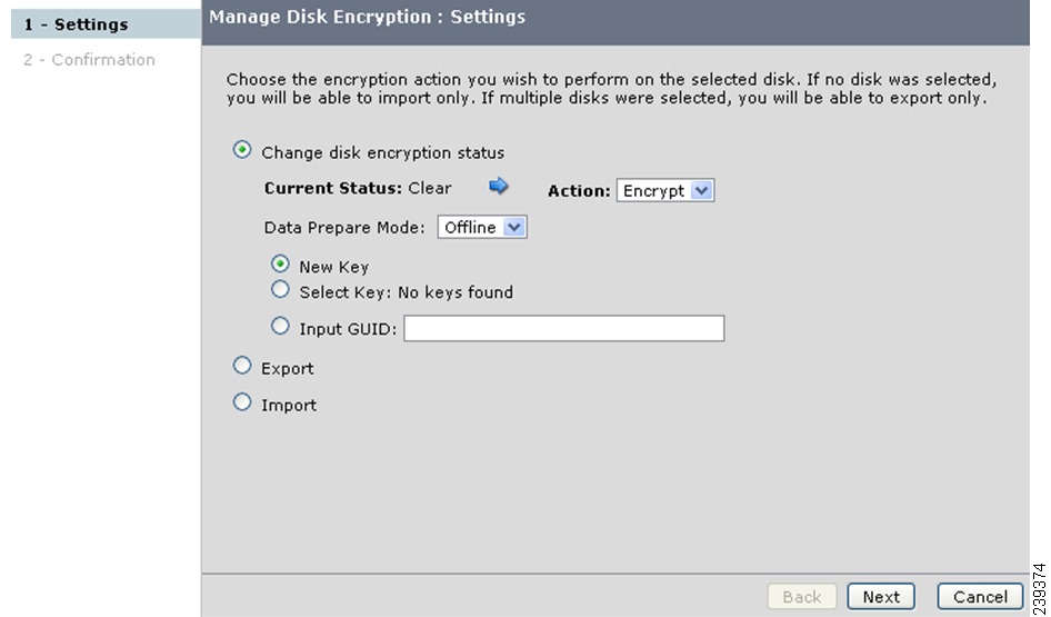
You can convert clear data to encrypted data by performing offline data preparation on a clear disk using the following options:
Note
If you click on the Manage Encryption button without selecting any disk, only the Import Operation button is enabled and only the Import option can be performed.
However, if you click on the Manage Encryption button after selecting multiple disks that are in the same state (clear or crypto or suspend), you can perform multiple disk operations such as Import, Export, and so on.
If you click on the Manage Encryption button after selecting multiple disks that are in different states (clear, crypto, and suspend), you only can perform Import and Export operations.
Using Select New Key
You can perform data preparation by selecting the New Key button. This operation converts clear data on a disk to encrypted data by generating a new disk key.
Detailed Steps
To perform data preparation on a clear disk using the New Key option, follow these steps:
Step 1
Step 2
The Current Status will be Clear. Select the required action Encrypt from the Action drop-down list.
For data preparation, ensure that the Prepare Data check box is checked.
Click New Key and click Next.
Step 3
The percentage of the disk preparation is displayed. Wait until the disk status changes to crypto.
When the data preparation is completed successfully, the disk status turns to Crypto.
Note
Caution
Note
We do not recommend aborting the data preparation as it will result in losing the contents. However, when you abort the data preparation operation, you need to recover the disk data from the backup. The recover state also should be consistent with the data in the backup.
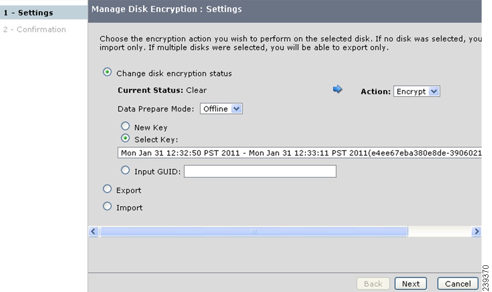
Using Select Key
You can perform data preparation by using the Select Key button. This operation converts clear data on a disk to encrypted data by using an existing disk key.
Detailed Steps
To perform data preparation on a clear disk using an existing key option, follow these steps:
Step 1
a.
b.
c.
d.
e.
Step 2
The percentage of the disk preparation is displayed. Wait until the status shows 100%.
When the data preparation is completed successfully, the disk status turns to Crypto.
Using Input GUID
You can perform data preparation by using the Input GUID option. This operation converts clear data on a disk to encrypted data by generating a new disk key.
To perform data preparation on a clear disk by providing the GUID, follow these steps:
Step 1
a.
b.
c.
d.
e.
Step 2
The percentage of completion of disk preparation is displayed. Wait until the status shows 100% and the disk state changes to crypto.
When the data preparation is completed successfully, the disk status turns to Crypto.
Performing Data Preparation on the Disk for Converting Encrypted Data to Clear Data
You can convert encrypted data to clear data on a disk by performing data preparation on an encrypted disk.
Detailed Steps
To convert encrypted data on a disk to clear state, follow these steps:
Step 1
a.
b.
c.
d.
Step 2
Step 3
Step 4
Rekeying on an Encrypted Disk
Detailed Steps
To rekey an encrypted disk, follow these steps:
Step 1
a.
b.
c.
Step 2
The percentage of the disk preparation is displayed. Wait until the disk status changes to crypto.
When the data preparation is completed successfully, the disk status turns to Crypto.
Recovering SME Disks
During data preparation if there are any failures, the data preparation process is aborted. If a failure occurs, the disk is put in a failed state and all host I/Os to the disk fails. This section describes the procedure to follow to recover the disk back to the state before the data preparation.
In signature mode, SME verifiesthe signature on the disk by comparing the disk information in the KMC. Any mismatch between the information in KMC and the signature results in disk failure.
Caution
Note
Recovering a Disk to Clear Status
Detailed Steps
To recover a failure disk to a clear disk, follow these steps:
Step 1
Step 2
Step 3
Step 4
The disk recovered successful message is displayed in the top of the screen showing the disk status as Clear.
Recovering a Disk to Encrypted Status
Detailed Steps
To recover a failure disk to a crypto disk, follow these steps:
Step 1
Step 2
Step 3
Step 4
The Disk recovered successful message is displayed in the top of the screen showing the disk status as Crypto.
Recovering a Disk Using Metadata Signature
Note
Detailed Steps
To recover the failure disk using the metadata, follow these steps:
Step 1
Step 2
Step 3
Step 4
The Disk recovered successful message is displayed in the top of the screen.
Recovering a Disk from Key Manager
Step 1
Step 2
Step 3
Step 4
The Disk recovered successful message is displayed in the top of the screen.
Performing Disk Encryption to Convert the Disk Status from Clear to Crypto
You can perform disk encryption operation to convert the disk status from clear to crypto using the following options:
Using Select New Key
You can perform disk encryption by selecting the New Key button. This operation converts the disk status from clear to crypto by using new disk key.
Detailed Steps
To perform disk encryption using the New Key option, follow these steps:
Step 1
a.
b.
c.
d.
Step 2
The percentage of the disk encryption is displayed. Wait until the status shows 100%.
When the disk encryption is completed successfully, the disk status turns to Crypto.
Using Select Key
You can perform disk encryption by using the Select Key option. This operation converts the disk status from clear to crypto by using an existing disk key.
Detailed Steps
To perform disk encryption using an existing key option, follow these steps:
Step 1
a.
b.
c.
d.
Step 2
The percentage of the disk preparation is displayed. Wait until the status shows 100%.
When the disk encryption is completed successfully, the disk status turns to Crypto.
Using Input GUID
You can perform disk encryption by using the Input GUID option. This operation converts the disk status from clear to crypto by using Input GUID.
Detailed Steps
To perform disk encryption using the Input GUID, follow these steps:
Step 1
a.
b.
c.
d.
Step 2
The percentage of the disk preparation is displayed. Wait until the status shows 100%.
When the disk encryption is completed successfully, the disk status turns to Crypto.
Performing Disk Encryption to Convert the Disk Status from Crypto to Clear
Detailed Steps
To perform disk encryption operation for converting the disk status from crypto to clear, follow these steps:
Step 1
a.
b.
c.
d.
Step 2
The percentage of the disk preparation is displayed. Wait until the status shows 100%.
When the disk encryption is completed successfully, the disk status turns to Clear.
Exporting and Importing Keys
You can explicitly export the keys that are generated during the key generation process or encryption process, and save the keys in a password-protected file.
Note
This section includes these exporting and importing tasks:
•
•
•
Exporting Keys for Single Disk
You can export keys for a single disk by selecting a particular disk.
Detailed Steps
To export keys for a single disk, follow these steps:
Step 1
Step 2
a.
b.
Step 3
Step 4
Exporting Keys for Multiple Disks
You can export keys for multiple disks by selecting multiple disks.
Detailed Steps
To export keys for multiple disks, follow these steps:
Step 1
Step 2
a.
b.
Step 3
Step 4
Importing Keys to a Single Disk or to a Disk Set
You can import keys to a single disk or import the disk keys to a defined disk set.
Detailed Steps
To import keys to a single disk or to a defined disk set, follow these steps:
Step 1
Step 2
a.
b.
Step 3
Step 4
The Import Successful message is displayed in the top of the screen.
Restoring an Encrypted Disk from a Deactivated Key
You can restore an encrypted disk from the deactivated key as follows:
•
•
Restoring a Deactivated Key Using the Select Key Option
Detailed Steps
To restore an encrypted disk from a deactivated key using the Select Key option, follow these steps:
Step 1
Step 2
a.
b.
c.
Step 3
The disk modified successful message is displayed.
Step 4
Step 5
Step 6
Restoring a Deactivated Key Using the Input GUID Option
Detailed Steps
To restore an encrypted disk from a deactivated key using the Input GUID, follow these steps:
Step 1
Step 2
a.
b.
c.
Step 3
The Resume Successful message is displayed in the top of the screen.
Configuring DKR
Caution
This section includes the following topics:
•
•
•
•
Creating Disk Key Replication
Note
Detailed Steps
To create disk key replication, follow these steps:
Step 1
Step 2
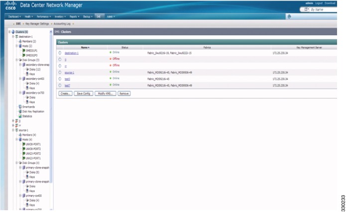
Figure 6-3 Clusters
Step 3
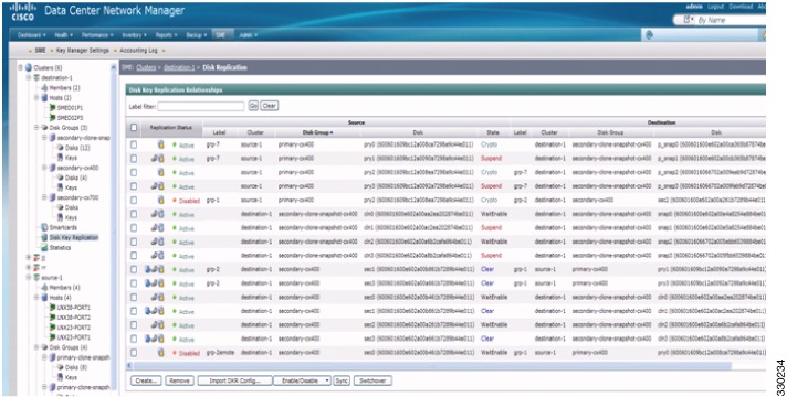
Figure 6-4 Disk Replication Creation
Step 4
Step 5
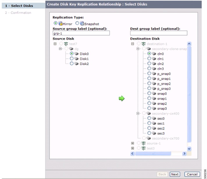
Figure 6-5 DKR Disk Selection
Note
Step 6
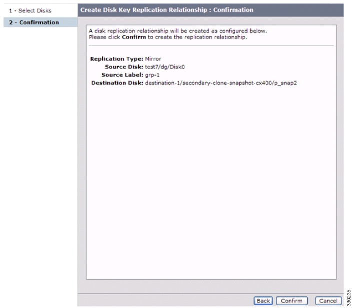
Figure 6-6 DKR Confirmation
The disk replication successful message is displayed showing the Replication Status as Disabled.
Note
All the relationships are stored in the KMC database. If the KMC database is down, you will not be able to see any relationships.
Enabling or Disabling Disk Key Replication
Detailed Steps
To enable disk key replication, follow these steps:
Step 1
Step 2
Step 3
The disk replication enable successful message is displayed at the top of the screen. The enabled disk's Replication Status is displayed as Active.
Step 4
Note
A source disk can be a source disk for multiple relationships. However, the destination disk can be the destination disk for only one relationship.
A source disk must be discovered and configured in the source cluster before an DKR relationship is established.
Note
To disable disk key replications, follow these steps:
Step 1
Step 2
Step 3
The disk replication disable successful message is displayed at the top of the screen. The disabled disk's Replication Status is displayed as Disabled.
Removing or Deleting Replication Relationships
Detailed Steps
To remove or delete replication relationships, follow these steps:
Step 1
Step 2
The replication relationships are removed or deleted.
Importing DKR Configurations
To import an DKR relationship configuration file, follow these steps:
Step 1
Step 2
The import file operation is processed and the DKR Config file is imported and successful import message is displayed.
Performing the Switchover Operation
Detailed Steps
You can perform a switchover operation to swap the source and destination in a disk key replication relationship. A switchover can only be performed on a DKR relationship in a Disabled state. To perform the switchover operation, follow these steps:
Step 1
Step 2
The relationships will have their source and destinations swapped. The relationships will still be in a disabled state.
Labels & Filtering
Labels can be associated with both sides of a disk key replication relationship. The DKR view provides the ability to filter based on these labels.
Performing the Sync Operation
You can perform the Sync operation on multiple relationships. To do this, follow these steps:
Step 1
Step 2
The relationships are replicated and are made similar and in sync with each other.
Configuring Key Management Operations
This section includes the following topics:
Replacing Smart Cards
This section describes how to replace smart cards for clusters.
Detailed Steps
To replace a smart card (Advanced security mode), follow these steps:
Step 1
Step 2
Step 3
The smart card replacement wizard is displayed.
Step 4
The SME Recovery Officer who owns the replacement smart card is prompted to log in and to insert the smart card to download the master key.
Step 5
Each member of the Cisco Recovery Officer quorum is requested to log in and present their smart card to authorize and authenticate the operation.
Step 6
Step 7
Step 8
To store the new master keyshares, follow these steps:
a.
A notification is shown that the first keyshare is successfully stored.
b.
A notification is shown that the second keyshare is successfully stored.
c.
A notification is shown that the third keyshare is successfully stored.
d.
A notification is shown that the fourth keyshare is successfully stored.
e.
A notification is shown that the fifth keyshare is successfully stored. Click Next to begin the automatic synchronization of volume groups.
Step 9
Step 10
Configuring Master Key Rekey
You can initiate the master key rekey operation using one of the following methods:
•
•
Prerequisites
•
•
•
•
•
•
•
•
–
–
–
–
–
–
–
–
Detailed Steps
Step 1
The Get Keyshares dialog box is displayed.
Note
Step 2
To rekey the master keyshares, follow these steps:
a.
A notification is shown that the first keyshare is successfully stored.
b.
A notification is shown that the second keyshare is successfully stored.
c.
A notification is shown that the third keyshare is successfully stored.
d.
A notification is shown that the fourth keyshare is successfully stored.
e.
A notification is shown that the fifth keyshare is successfully stored. Click Next to begin the rekeying process.
Step 3
The Rekey Master Key configuration is successful.
Resume Sync
When you have all the shares stored in the smart card and when there are discrepancies in the fabric and when MKR fails, click Resume Sync to resume the MKR operation.
Verifying the SME Disk Management Configuration
To display the SME disk management configuration information, perform one of the following tasks:
For detailed information about the fields in the output from these commands, refer to the Cisco MDS 9000 Family NX-OS Command Reference.
Monitoring SME Disk Management
This section includes the following topics:
•
Viewing Host Details
You can view detailed information about hosts in a SME cluster. Information for a specific host includes the disk group membership, paths from the host to the target, VSAN, fabric, status, and the disk device.
To view the host details, select a host in the navigation pane.
Viewing Disk Group Details
You can view detailed information about disk groups in a SME cluster. Information for a specific disk includes the disk group membership, device description, serial number, and the host and target PWWN.
To view the disk group details, select a disk group in the navigation pane.
Viewing Disk Details
You can view details and information about the disks in a disk group in an SME cluster. Information for a specific disk includes the path information and the disk status.
To view the disk details, select a disk from the navigation pane.
Viewing Disk Path Details
You can view the disk path details of a disk in a disk group in an SME cluster. Information for a specific disk includes the path information and the disk status.
To view the disk path details, select a disk from the navigation pane. The details are displayed in the Disk Details and Configured Paths section.
Viewing Signature Mode Clusters
You can view the detailed information of SME clusters that are in signature mode. To view the cluster details, click clusters from the navigation pane.
Viewing SME Disk Information Using the CLI
Use the show sme cluster command to view information about a cluster.
switch# show sme clusterSME Cluster is dest1Cluster ID is 0x29ab000dec3f1402Cluster status is onlineSecurity mode is basicTotal Nodes are 2Recovery Scheme is 1 out of 1Fabric[0] is Fabric_jlwu9216i-19Fabric[1] is Fabric_jlwu9222i-15Primary KMC server 172.25.230.33:8800 is provisioned, connection state is noneSecondary KMC server has not been provisionedMaster Key GUID is b020829d0f009fa2-4d496531313d981e, Version: 0Shared Key Mode is Not EnabledAuto Vol Group is Not EnabledTape Compression is EnabledTape Key Recycle Policy is EnabledKey On Tape is Not EnabledCluster Infra Status : OperationalCluster is Administratively UpCluster Config Version : 2445SSL for KMC : Not ConfiguredSSL for ICN : Not ConfiguredCluster is Disk capableCluster Metadata On Disk is Set: 64 megabytes <!---64 megabytes indicates a signature mode cluster>
Note
Use the show sme cluster detail command to view detail information about a cluster.
switch# show sme cluster detailSME Cluster is dest1Cluster ID is 0x29ab000dec3f1402Cluster status is onlineSecurity mode is basicTotal Nodes are 2Recovery Scheme is 1 out of 1Fabric[0] is Fabric_jlwu9216i-19Fabric[1] is Fabric_jlwu9222i-15Primary KMC server 172.25.230.33:8800 is provisioned, connection state is noneSecondary KMC server has not been provisionedMaster Key GUID is b020829d0f009fa2-4d496531313d981e, Version: 0Shared Key Mode is Not EnabledAuto Vol Group is Not EnabledTape Compression is EnabledTape Key Recycle Policy is EnabledKey On Tape is Not EnabledCluster Infra Status : OperationalCluster is Administratively UpCluster Config Version : 2445SSL for KMC : Not ConfiguredSSL for ICN : Not ConfiguredCluster is Disk capableCluster Metadata On Disk is Set: 64 MegabytesUse the show sme cluster summary command to view summary information about the cluster.
switch# show sme cluster summary
-------------------------------------------------------------------------------
Cluster ID Security Mode Status-------------------------------------------------------------------------------C 0x20eb000dec3f45c2 basic online -------------------------------------------------------------------------------Use the show sme cluster clustername command to view information about a particular cluster.
switch# show sme cluster cSME Cluster is CCluster ID is 0x29ab000dec3f1402Cluster status is onlineSecurity mode is basicTotal Nodes are 2Recovery Scheme is 1 out of 1Fabric[0] is Fabric_jlwu9216i-19Fabric[1] is Fabric_jlwu9222i-15Primary KMC server 172.25.230.33:8800 is provisioned, connection state is noneSecondary KMC server has not been provisionedMaster Key GUID is b020829d0f009fa2-4d496531313d981e, Version: 0Shared Key Mode is Not EnabledAuto Vol Group is Not EnabledTape Compression is EnabledTape Key Recycle Policy is EnabledKey On Tape is Not EnabledCluster Infra Status : OperationalCluster is Administratively UpCluster Config Version : 2445SSL for KMC : Not ConfiguredSSL for ICN : Not ConfiguredCluster is Disk capableCluster Metadata On Disk is Set: 64 MegabytesUse the show sme cluster clustername detail command to view detail information about a particular cluster.
switch# show sme cluster c detailSME Cluster is CCluster ID is 0x29ab000dec3f1402Cluster status is onlineSecurity mode is basicTotal Nodes are 2Recovery Scheme is 1 out of 1Fabric[0] is Fabric_jlwu9216i-19Fabric[1] is Fabric_jlwu9222i-15Primary KMC server 172.25.230.33:8800 is provisioned, connection state is noneSecondary KMC server has not been provisionedMaster Key GUID is b020829d0f009fa2-4d496531313d981e, Version: 0Shared Key Mode is Not EnabledAuto Vol Group is Not EnabledTape Compression is EnabledTape Key Recycle Policy is EnabledKey On Tape is Not EnabledCluster Infra Status : OperationalCluster is Administratively UpCluster Config Version : 2445SSL for KMC : Not ConfiguredSSL for ICN : Not ConfiguredCluster is Disk capableCluster Metadata On Disk is Set: 64 MegabytesUse the show sme cluster clustername summary command to view summary information about a particular cluster.
switch# show sme cluster c summary
-------------------------------------------------------------------------------
Cluster ID Security Mode Status-------------------------------------------------------------------------------C 0x20eb000dec3f45c2 basic online -------------------------------------------------------------------------------Use the show sme cluster clustername disk group command to view the disk group information in particular cluster.
switch# show sme cluster c disk-group------------------------------------Disk Group Name Total Disks------------------------------------DG 8Use the show sme cluster clustername disk-group DG command to view information about a disk group in a cluster.
switch# show sme cluster scluster20 disk-group dg1Disk group dg1Number of disks is 16Disk group dg1Number of disks is 16Disk Disk0 is clearDescription is LSI INF-01-00Vendor ID is LSIProduct ID is INF-01-00Device ID is 600a0bb0000000005006218003813000Encryption is Not EnabledDisk Disk1 is clearDescription is LSI INF-01-00Vendor ID is LSIProduct ID is INF-01-00Device ID is 600a0bb0000000015006218003813000Encryption is Not EnabledDisk Disk10 is clearDescription is LSI INF-01-00Vendor ID is LSIProduct ID is INF-01-00Device ID is 600a0bb00000000a5006218003813000Encryption is Not EnabledDisk Disk11 is clearDescription is LSI INF-01-00Vendor ID is LSIProduct ID is INF-01-00Device ID is 600a0bb00000000b5006218003813000Encryption is Not EnabledDisk Disk12 is clearDescription is LSI INF-01-00Vendor ID is LSIProduct ID is INF-01-00Device ID is 600a0bb00000000c5006218003813000Encryption is Not EnabledDisk Disk13 is clearDescription is LSI INF-01-00Vendor ID is LSIProduct ID is INF-01-00Device ID is 600a0bb00000000d5006218003813000Encryption is Not EnabledDisk Disk14 is clearDescription is LSI INF-01-00Vendor ID is LSIProduct ID is INF-01-00Device ID is 600a0bb00000000e5006218003813000Encryption is Not EnabledDisk Disk15 is clearDescription is LSI INF-01-00Vendor ID is LSIProduct ID is INF-01-00Device ID is 600a0bb00000000f5006218003813000Encryption is Not EnabledDisk Disk2 is clearDescription is LSI INF-01-00Vendor ID is LSIProduct ID is INF-01-00Device ID is 600a0bb0000000025006218003813000Encryption is Not EnabledDisk Disk3 is clearDescription is LSI INF-01-00Vendor ID is LSIProduct ID is INF-01-00Device ID is 600a0bb0000000035006218003813000Encryption is Not EnabledDisk Disk4 is clearDescription is LSI INF-01-00Vendor ID is LSIProduct ID is INF-01-00Device ID is 600a0bb0000000045006218003813000Encryption is Not EnabledDisk Disk5 is clearDescription is LSI INF-01-00Vendor ID is LSIProduct ID is INF-01-00Device ID is 600a0bb0000000055006218003813000Encryption is Not EnabledDisk Disk6 is clearDescription is LSI INF-01-00Vendor ID is LSIProduct ID is INF-01-00Device ID is 600a0bb0000000065006218003813000Encryption is Not EnabledDisk Disk7 is clearDescription is LSI INF-01-00Vendor ID is LSIProduct ID is INF-01-00Device ID is 600a0bb0000000075006218003813000Encryption is Not EnabledDisk Disk8 is clearDescription is LSI INF-01-00Vendor ID is LSIProduct ID is INF-01-00Device ID is 600a0bb0000000085006218003813000Encryption is Not EnabledDisk Disk9 is clearDescription is LSI INF-01-00Vendor ID is LSIProduct ID is INF-01-00Device ID is 600a0bb0000000095006218003813000Encryption is Not EnabledUse the show sme cluster clustername disk-group disk-group name DG disk command to view information about a disk in the disk group.
switch# show sme cluster scluster20 disk-group dg1 diskDisk group dg1Number of disks is 16Disk group dg1Number of disks is 16Disk Disk0 is clearDescription is LSI INF-01-00Vendor ID is LSIProduct ID is INF-01-00Device ID is 600a0bb0000000005006218003813000Encryption is Not EnabledDisk Disk1 is clearDescription is LSI INF-01-00Vendor ID is LSIProduct ID is INF-01-00Device ID is 600a0bb0000000015006218003813000Encryption is Not EnabledDisk Disk10 is clearDescription is LSI INF-01-00Vendor ID is LSIProduct ID is INF-01-00Device ID is 600a0bb00000000a5006218003813000Encryption is Not EnabledDisk Disk11 is clearDescription is LSI INF-01-00Vendor ID is LSIProduct ID is INF-01-00Device ID is 600a0bb00000000b5006218003813000Encryption is Not EnabledDisk Disk12 is clearDescription is LSI INF-01-00Vendor ID is LSIProduct ID is INF-01-00Device ID is 600a0bb00000000c5006218003813000Encryption is Not EnabledDisk Disk13 is clearDescription is LSI INF-01-00Vendor ID is LSIProduct ID is INF-01-00Device ID is 600a0bb00000000d5006218003813000Encryption is Not EnabledDisk Disk14 is clearDescription is LSI INF-01-00Vendor ID is LSIProduct ID is INF-01-00Device ID is 600a0bb00000000e5006218003813000Encryption is Not EnabledDisk Disk15 is clearDescription is LSI INF-01-00Vendor ID is LSIProduct ID is INF-01-00Device ID is 600a0bb00000000f5006218003813000Encryption is Not EnabledDisk Disk2 is clearDescription is LSI INF-01-00Vendor ID is LSIProduct ID is INF-01-00Device ID is 600a0bb0000000025006218003813000Encryption is Not EnabledDisk Disk3 is clearDescription is LSI INF-01-00Vendor ID is LSIProduct ID is INF-01-00Device ID is 600a0bb0000000035006218003813000Encryption is Not EnabledDisk Disk4 is clearDescription is LSI INF-01-00Vendor ID is LSIProduct ID is INF-01-00Device ID is 600a0bb0000000045006218003813000Encryption is Not EnabledDisk Disk5 is clearDescription is LSI INF-01-00Vendor ID is LSIProduct ID is INF-01-00Device ID is 600a0bb0000000055006218003813000Encryption is Not EnabledDisk Disk6 is clearDescription is LSI INF-01-00Vendor ID is LSIProduct ID is INF-01-00Device ID is 600a0bb0000000065006218003813000Encryption is Not EnabledDisk Disk7 is clearDescription is LSI INF-01-00Vendor ID is LSIProduct ID is INF-01-00Device ID is 600a0bb0000000075006218003813000Encryption is Not EnabledDisk Disk8 is clearDescription is LSI INF-01-00Vendor ID is LSIProduct ID is INF-01-00Device ID is 600a0bb0000000085006218003813000Encryption is Not EnabledDisk Disk9 is clearDescription is LSI INF-01-00Vendor ID is LSIProduct ID is INF-01-00Device ID is 600a0bb0000000095006218003813000Encryption is Not EnabledUse the show sme cluster clustername disk-group disk-group name disk disk name command to view information about a disk in the disk group.
switch# show sme cluster scluster20 disk-group dg1 disk Disk 0Disk Disk0 is clearDescription is LSI INF-01-00Vendor ID is LSIProduct ID is INF-01-00Device ID is 600a0bb0000000005006218003813000Encryption is Not EnabledPathsHost 10:00:0e:91:c3:76:5c:00 Target 50:06:21:80:03:81:30:00 Lun 0x0000 vsan 100 [Fabric_sw-A-9222i-95]Is online (SUCCESS), configuredUse the show sme cluster clustername disk detail command to view detail information about a disk in a cluster.
switch# show sme cluster scluster20 disk detailDisk 1 is clearModel is LSI INF-01-00Vendor ID is LSIProduct ID is INF-01-00Device ID is 600a0bb0000000095006218003813000Is configured as disk device Disk9 in disk group dg1PathsHost 10:00:0e:91:c3:76:5c:00 Target 50:06:21:80:03:81:30:00 Lun 0x0009 vsan 100Is online (SUCCESS), configuredDisk 2 is clearModel is LSI INF-01-00Vendor ID is LSIProduct ID is INF-01-00Device ID is 600a0bb0000000005006218003813000Is configured as disk device Disk0 in disk group dg1PathsHost 10:00:0e:91:c3:76:5c:00 Target 50:06:21:80:03:81:30:00 Lun 0x0000 vsan 100Is online (SUCCESS), configuredDisk 3 is clearModel is LSI INF-01-00Vendor ID is LSIProduct ID is INF-01-00Device ID is 600a0bb00000000f5006218003813000Is configured as disk device Disk15 in disk group dg1PathsHost 10:00:0e:91:c3:76:5c:00 Target 50:06:21:80:03:81:30:00 Lun 0x000f vsan 100Is online (SUCCESS), configuredDisk 4 is clearModel is LSI INF-01-00Vendor ID is LSIProduct ID is INF-01-00Device ID is 600a0bb0000000025006218003813000Is configured as disk device Disk2 in disk group dg1PathsHost 10:00:0e:91:c3:76:5c:00 Target 50:06:21:80:03:81:30:00 Lun 0x0002 vsan 100Is online (SUCCESS), configuredDisk 5 is clearModel is LSI INF-01-00Vendor ID is LSIProduct ID is INF-01-00Device ID is 600a0bb0000000085006218003813000Is configured as disk device Disk8 in disk group dg1PathsHost 10:00:0e:91:c3:76:5c:00 Target 50:06:21:80:03:81:30:00 Lun 0x0008 vsan 100Is online (SUCCESS), configuredDisk 6 is clearModel is LSI INF-01-00Vendor ID is LSIProduct ID is INF-01-00Device ID is 600a0bb00000000b5006218003813000Is configured as disk device Disk11 in disk group dg1PathsHost 10:00:0e:91:c3:76:5c:00 Target 50:06:21:80:03:81:30:00 Lun 0x000b vsan 100Is online (SUCCESS), configuredDisk 7 is clearModel is LSI INF-01-00Vendor ID is LSIProduct ID is INF-01-00Device ID is 600a0bb0000000065006218003813000Is configured as disk device Disk6 in disk group dg1PathsHost 10:00:0e:91:c3:76:5c:00 Target 50:06:21:80:03:81:30:00 Lun 0x0006 vsan 100Is online (SUCCESS), configuredDisk 8 is clearModel is LSI INF-01-00Vendor ID is LSIProduct ID is INF-01-00Device ID is 600a0bb0000000055006218003813000Is configured as disk device Disk5 in disk group dg1PathsHost 10:00:0e:91:c3:76:5c:00 Target 50:06:21:80:03:81:30:00 Lun 0x0005 vsan 100Is online (SUCCESS), configuredDisk 9 is clearModel is LSI INF-01-00Vendor ID is LSIProduct ID is INF-01-00Device ID is 600a0bb0000000075006218003813000Is configured as disk device Disk7 in disk group dg1PathsHost 10:00:0e:91:c3:76:5c:00 Target 50:06:21:80:03:81:30:00 Lun 0x0007 vsan 100Is online (SUCCESS), configuredDisk 10 is clearModel is LSI INF-01-00Vendor ID is LSIProduct ID is INF-01-00Device ID is 600a0bb0000000035006218003813000Is configured as disk device Disk3 in disk group dg1PathsHost 10:00:0e:91:c3:76:5c:00 Target 50:06:21:80:03:81:30:00 Lun 0x0003 vsan 100Is online (SUCCESS), configuredDisk 11 is clearModel is LSI INF-01-00Vendor ID is LSIProduct ID is INF-01-00Device ID is 600a0bb0000000045006218003813000Is configured as disk device Disk4 in disk group dg1PathsHost 10:00:0e:91:c3:76:5c:00 Target 50:06:21:80:03:81:30:00 Lun 0x0004 vsan 100Is online (SUCCESS), configuredDisk 12 is clearModel is LSI INF-01-00Vendor ID is LSIProduct ID is INF-01-00Device ID is 600a0bb0000000015006218003813000Is configured as disk device Disk1 in disk group dg1PathsHost 10:00:0e:91:c3:76:5c:00 Target 50:06:21:80:03:81:30:00 Lun 0x0001 vsan 100Is online (SUCCESS), configuredDisk 13 is clearModel is LSI INF-01-00Vendor ID is LSIProduct ID is INF-01-00Device ID is 600a0bb00000000d5006218003813000Is configured as disk device Disk13 in disk group dg1PathsHost 10:00:0e:91:c3:76:5c:00 Target 50:06:21:80:03:81:30:00 Lun 0x000d vsan 100Is online (SUCCESS), configuredDisk 14 is clearModel is LSI INF-01-00Vendor ID is LSIProduct ID is INF-01-00Device ID is 600a0bb00000000c5006218003813000Is configured as disk device Disk12 in disk group dg1PathsHost 10:00:0e:91:c3:76:5c:00 Target 50:06:21:80:03:81:30:00 Lun 0x000c vsan 100Is online (SUCCESS), configuredDisk 15 is clearModel is LSI INF-01-00Vendor ID is LSIProduct ID is INF-01-00Device ID is 600a0bb00000000a5006218003813000Is configured as disk device Disk10 in disk group dg1PathsHost 10:00:0e:91:c3:76:5c:00 Target 50:06:21:80:03:81:30:00 Lun 0x000a vsan 100Is online (SUCCESS), configuredDisk 16 is clearModel is LSI INF-01-00Vendor ID is LSIProduct ID is INF-01-00Device ID is 600a0bb00000000e5006218003813000Is configured as disk device Disk14 in disk group dg1PathsHost 10:00:0e:91:c3:76:5c:00 Target 50:06:21:80:03:81:30:00 Lun 0x000e vsan 100Is online (SUCCESS), configuredUse the show sme cluster clustername disk summary command to view summary information about a particular disk in a cluster.
switch# show sme cluster c disk summary
-------------------------------------------------------------------------------
Target WWN Lun Description Crypto-Disk Status-------------------------------------------------------------------------------50:06:01:6b:30:60:06:d6 0x0002 DGC DISK Disk7 clear50:06:01:6b:30:60:06:d6 0x0000 DGC DISK Disk5 clear50:06:01:6b:30:60:06:d6 0x0001 DGC DISK Disk6 clear50:06:01:63:30:60:06:d6 0x0003 DGC RAID 5 Disk3 clear50:06:01:63:30:60:06:d6 0x0004 DGC RAID 5 Disk4 clear50:06:01:63:30:60:06:d6 0x0001 DGC RAID 5 Disk1 clear50:06:01:63:30:60:06:d6 0x0002 DGC RAID 5 Disk2 clear50:06:01:63:30:60:06:d6 0x0000 DGC RAID 5 Disk0 clearUse the show sme cluster clustername it-nexus command to view detail information about the IT-nexuses in a particular cluster.
switch# show sme cluster c it-nexus
-------------------------------------------------------------------------------
Host WWN, VSAN Status Switch InterfaceTarget WWN-------------------------------------------------------------------------------21:00:00:1b:32:8a:1d:4c,50:06:01:63:30:60:06:d6 2 online 172.28.234.68 sme1/121:01:00:1b:32:aa:49:4c,50:06:01:6b:30:60:06:d6 2 online 172.28.234.68 sme1/121:02:00:1b:32:ca:49:4c,50:06:01:6b:30:60:06:d6 2 online 172.28.234.68 sme1/1Use the show sme cluster clustername interface detail command to view detail information about the SME interfaces in a cluster.
Interface sme1/1 belongs to local switchStatus is upRSA Certificate is (len 247 fingerprint SHA1:: 87:2f:16:6d:91:ec:8f:cb:95:3a:df:6b:c6:49:c3:67:c4:a9:39:6f:)-----BEGIN RSA PUBLIC KEY-----MIGHAoGBAMJGt4JoIhfV3KU6eJPdfmzIjYLqbZ2mA3VdJ7T86btzyMhpZZI4x76OuCvLxEIuKW+p/XRqhpV4AN7YQDVCw0OB3dacXfRQjM8EdoC6lMXDGsKCzYzti51HZqQvAKCMydz/P3CSbVx3MsoOeDuvv/Hj6wvIngtDGfvHkWms9b1lAgED-----END RSA PUBLIC KEY-----Use the show sme cluster clustername interface summary command to view summary information about the SME interfaces in a cluster.
switch# show sme cluster c interface summary
-------------------------------------------------------------------------------
Switch Interface Status-------------------------------------------------------------------------------local switch sme1/1 upUse the show sme cluster clustername interface sme sme-interface command to view information about a particular SME interface in a cluster.
switch# show sme cluster c interface sme 1/1Interface sme1/1 belongs to local switchStatus is upUse the show sme cluster clustername lun crypto-status command to view crypto status of the LUNs in a cluster.
switch# show sme cluster c lun crypto-statusLUN (Serial Number) Encryption------------------------------------------------------------------------------LUN---cpp_lun_ndx 0x29sme_enabled 0vendor_id DGCproduct_id DISKdevice_id 10493CF4prod_rev_level 0216vendor_specific 860000AB71CLcluster_name Cdg_name DGdevice_name Disk7max_lba 0x27fffffblk_sz 0x200disk_state 0x1current disk fsm state SMED_CPP_DISK_ST_CLEAR_DISKcur_key_guid 0000000000000000-0000000000000000new_key_guid 0000000000000000-0000000000000000cur_key_obj (nil)new_key_obj (nil)dp (nil)total itl count 2active itl count 2lun hold count 0Not lockedI 21:01:00:1b:32:aa:49:4c T 50:06:01:6b:30:60:06:d6 L 0x0002(SMED_ISAPI_ITL_ST_UP_CLEAR [lock event=NONE])I 21:02:00:1b:32:ca:49:4c T 50:06:01:6b:30:60:06:d6 L 0x0002(SMED_ISAPI_ITL_ST_UP_CLEAR [lock event=NONE])LUN---cpp_lun_ndx 0x27sme_enabled 0vendor_id DGCproduct_id DISKdevice_id 93B1508Bprod_rev_level 0216vendor_specific 8000009529CLcluster_name Cdg_name DGdevice_name Disk5max_lba 0x27fffffblk_sz 0x200disk_state 0x1current disk fsm state SMED_CPP_DISK_ST_CLEAR_DISKcur_key_guid 0000000000000000-0000000000000000new_key_guid 0000000000000000-0000000000000000cur_key_obj (nil)new_key_obj (nil)dp (nil)total itl count 2active itl count 2lun hold count 0Not lockedI 21:01:00:1b:32:aa:49:4c T 50:06:01:6b:30:60:06:d6 L 0x0000(SMED_ISAPI_ITL_ST_UP_CLEAR [lock event=NONE])I 21:02:00:1b:32:ca:49:4c T 50:06:01:6b:30:60:06:d6 L 0x0000(SMED_ISAPI_ITL_ST_UP_CLEAR [lock event=NONE])LUN---cpp_lun_ndx 0x28sme_enabled 0vendor_id DGCproduct_id DISKdevice_id F074E188prod_rev_level 0216vendor_specific 850000AA73CLcluster_name Cdg_name DGdevice_name Disk6max_lba 0x27fffffblk_sz 0x200disk_state 0x1current disk fsm state SMED_CPP_DISK_ST_CLEAR_DISKcur_key_guid 0000000000000000-0000000000000000new_key_guid 0000000000000000-0000000000000000cur_key_obj (nil)new_key_obj (nil)dp (nil)total itl count 2active itl count 2lun hold count 0Not lockedI 21:01:00:1b:32:aa:49:4c T 50:06:01:6b:30:60:06:d6 L 0x0001(SMED_ISAPI_ITL_ST_UP_CLEAR [lock event=NONE])I 21:02:00:1b:32:ca:49:4c T 50:06:01:6b:30:60:06:d6 L 0x0001(SMED_ISAPI_ITL_ST_UP_CLEAR [lock event=NONE])LUN---cpp_lun_ndx 0x25sme_enabled 0vendor_id DGCproduct_id RAID 5device_id 3C2590FBprod_rev_level 0216vendor_specific 39000061BDCLcluster_name Cdg_name DGdevice_name Disk3max_lba 0x9fffffblk_sz 0x200disk_state 0x1current disk fsm state SMED_CPP_DISK_ST_CLEAR_DISKcur_key_guid 0000000000000000-0000000000000000new_key_guid 0000000000000000-0000000000000000cur_key_obj (nil)new_key_obj (nil)dp (nil)total itl count 1active itl count 1lun hold count 0Not lockedI 21:00:00:1b:32:8a:1d:4c T 50:06:01:63:30:60:06:d6 L 0x0003(SMED_ISAPI_ITL_ST_UP_CLEAR [lock event=NONE])LUN---cpp_lun_ndx 0x26sme_enabled 0vendor_id DGCproduct_id RAID 5device_id 8B09E6E9prod_rev_level 0216vendor_specific 3A000061D3CLcluster_name Cdg_name DGdevice_name Disk4max_lba 0x9fffffblk_sz 0x200disk_state 0x1current disk fsm state SMED_CPP_DISK_ST_CLEAR_DISKcur_key_guid 0000000000000000-0000000000000000new_key_guid 0000000000000000-0000000000000000cur_key_obj (nil)new_key_obj (nil)dp (nil)total itl count 1active itl count 1lun hold count 0Not lockedI 21:00:00:1b:32:8a:1d:4c T 50:06:01:63:30:60:06:d6 L 0x0004(SMED_ISAPI_ITL_ST_UP_CLEAR [lock event=NONE])LUN---cpp_lun_ndx 0x23sme_enabled 0vendor_id DGCproduct_id RAID 5device_id 90D80D94prod_rev_level 0216vendor_specific 3700006182CLcluster_name Cdg_name DGdevice_name Disk1max_lba 0x9fffffblk_sz 0x200disk_state 0x1current disk fsm state SMED_CPP_DISK_ST_CLEAR_DISKcur_key_guid 0000000000000000-0000000000000000new_key_guid 0000000000000000-0000000000000000cur_key_obj (nil)new_key_obj (nil)dp (nil)total itl count 1active itl count 1lun hold count 0Not lockedI 21:00:00:1b:32:8a:1d:4c T 50:06:01:63:30:60:06:d6 L 0x0001(SMED_ISAPI_ITL_ST_UP_CLEAR [lock event=NONE])LUN---cpp_lun_ndx 0x24sme_enabled 0vendor_id DGCproduct_id RAID 5device_id 930ED44Fprod_rev_level 0216vendor_specific 38000061A5CLcluster_name Cdg_name DGdevice_name Disk2max_lba 0x9fffffblk_sz 0x200disk_state 0x1current disk fsm state SMED_CPP_DISK_ST_CLEAR_DISKcur_key_guid 0000000000000000-0000000000000000new_key_guid 0000000000000000-0000000000000000cur_key_obj (nil)new_key_obj (nil)dp (nil)total itl count 1active itl count 1lun hold count 0Not lockedI 21:00:00:1b:32:8a:1d:4c T 50:06:01:63:30:60:06:d6 L 0x0002(SMED_ISAPI_ITL_ST_UP_CLEAR [lock event=NONE])LUN---cpp_lun_ndx 0x22sme_enabled 0vendor_id DGCproduct_id RAID 5device_id CC1BCB3Aprod_rev_level 0216vendor_specific 360000616BCLcluster_name Cdg_name DGdevice_name Disk0max_lba 0x9fffffblk_sz 0x200disk_state 0x1current disk fsm state SMED_CPP_DISK_ST_CLEAR_DISKcur_key_guid 0000000000000000-0000000000000000new_key_guid 0000000000000000-0000000000000000cur_key_obj (nil)new_key_obj (nil)dp (nil)total itl count 1active itl count 1lun hold count 0Not lockedI 21:00:00:1b:32:8a:1d:4c T 50:06:01:63:30:60:06:d6 L 0x0000(SMED_ISAPI_ITL_ST_UP_CLEAR [lock event=NONE])Use the show sme cluster clustername load-balancing command to view the load-balancing status of the cluster.
switch# show sme cluster c load-balancingLoad balancing status is enabled for cluster CUse the show sme cluster clustername node command to view information about the nodes in a cluster.
switch# show sme cluster c nodeNode 172.28.234.54 is remote switchNode ID is 2Status is onlineNode is not master switchFabric is Fabric_sw-sme-9513-54Node 172.28.234.68 is local switchNode ID is 1Status is onlineNode is the master switchFabric is Fabric_sw-sme-9513-54Use the show sme cluster clustername node remote-switch command to view information about a particular remote node in a cluster.
switch# show sme cluster c node 172.28.234.54Node 172.28.234.54 is remote switchNode ID is 2Status is onlineNode is not master switchFabric is Fabric_sw-sme-9513-54Use the show sme cluster clustername node summary command to view summary information about the nodes in a cluster.
switch# show sme cluster c node summary-------------------------------------------------------------------------------Switch Status Master Node ID-------------------------------------------------------------------------------172.28.234.54 online no 2local switch online yes 1Use the show sme cluster clustername key database command to view information about the keys in a cluster.
switch# show sme cluster c key databaseKey Type is master keyGUID is 2ebddb1dbf180660-c0e4add77be8e8a0Cluster is C, Master Key Version is 0Key Type is disk keyGUID is 5a8adb8aca98106f-dd61016f5fb8b543Cluster is C, Crypto disk group is DGCrypto disk is Disk1Key Type is disk keyGUID is dc203fa33cd267ad-dd2e7513e307521fCluster is C, Crypto disk group is DGCrypto disk is Disk0Use the show sme cluster clustername key database detail command to view detail information about the keys in a cluster.
switch# show sme cluster c key database detailKey Type is master keyGUID is 2ebddb1dbf180660-c0e4add77be8e8a0Cluster is C, Master Key Version is 0Key status is activeKey was created at Mon Oct 04 13:38:41 UTC 2010Key length is 32Key Type is disk keyGUID is 5a8adb8aca98106f-dd61016f5fb8b543Cluster is C, Crypto disk group is DGCrypto disk is Disk1Key status is activeKey was created at Mon Oct 04 13:58:23 UTC 2010Key length is 32Key data type is symmetric key wrapSymmetric key wrapping version is 0Symmetric crypto algorithm is aes-cbcAuthentication algorithm used is sha-256 and valueG5UvNvtQC67CGfbJBWV1xs+zUKF4CIOIrk+tfG+dPQY=IV length is 16 and valuejAMWrbbqtDou2DmSmlddmQAAAAAAAAAAAAAAAAAAAAA=Key Object is wrapped by 2ebddb1dbf180660-c0e4add77be8e8a0Key data length is 80Encrypted data isqLOTc/pr9NvMcRTgwePgzwpJaBoDxzLevYXh1gw9c+fbZlp4kabTYUM7QGTrZKFkkJPOPO/XPSn9VVKVYvNSCguQV0teq6VovdUqeDyht9g=Key Type is disk keyGUID is dc203fa33cd267ad-dd2e7513e307521fCluster is C, Crypto disk group is DGCrypto disk is Disk0Key status is activeKey was created at Mon Oct 04 13:57:56 UTC 2010Key length is 32Key data type is symmetric key wrapSymmetric key wrapping version is 0Symmetric crypto algorithm is aes-cbcAuthentication algorithm used is sha-256 and value8isr/LRaHdqQmlGPagCq9reDOYLQiFdImmQfmIRsu9s=IV length is 16 and valuegJfKQqKTsU8iJ5HrGQR3GwAAAAAAAAAAAAAAAAAAAAA=Key Object is wrapped by 2ebddb1dbf180660-c0e4add77be8e8a0Key data length is 80Encrypted data iszL+syhPqSQfXy8zAwLfrntbIcjIux+dIjPQWQ0Jk/zpVTmRDKT6RlzFmkN3ibXaqzba6yrfCXUGMmWX/KK7CdEQtkWk1ecUzk+zvbYtdq50=Use the show sme cluster clustername key database summary command to view summary information about the keys in a cluster.
switch# show sme cluster c key database summary-------------------------------------------------------------------------------Key Type GUID-------------------------------------------------------------------------------master key 2ebddb1dbf180660-c0e4add77be8e8a0disk key 5a8adb8aca98106f-dd61016f5fb8b543disk key dc203fa33cd267ad-dd2e7513e307521fUse the show sme cluster clustername key database guid GUID command to view key information in a cluster for a particular GUID.
switch# show sme cluster c key database guid 2ebddb1dbf180660-c0e4add77be8e8a0Key Type is master keyGUID is 2ebddb1dbf180660-c0e4add77be8e8a0Cluster is C, Master Key Version is 0Use the show sme cluster clustername key database guid GUID summary command to view summary information about the key in a cluster for GUID.
switch# show sme cluster C key database guid 2ebddb1dbf180660-c0e4add77be8e8a0 summary-------------------------------------------------------------------------------Key Type GUID-------------------------------------------------------------------------------master key 2ebddb1dbf180660-c0e4add77be8e8a0Use the show sme cluster clustername key database guid GUID detail command to view detail information about the key in a cluster for a particular GUID.
switch# show sme cluster c key database guid 2ebddb1dbf180660-c0e4add77be8e8a0 detailKey Type is master keyGUID is 2ebddb1dbf180660-c0e4add77be8e8a0Cluster is C, Master Key Version is 0Key status is activeKey was created at Mon Oct 04 13:38:41 UTC 2010Key length is 32Use the show sme cluster clustername recovery officer command to view information about the SME cluster recovery officer.
switch# show sme cluster c recovery officerRecovery Officer 1 is setMaster Key Version is 0Recovery Share Version is 0Recovery Share Index is 1Recovery Scheme is 1 out of 1Recovery Officer Label isRecovery share protected by a passwordKey Type is master key shareCluster is C, Master Key Version is 0Recovery Share Version is 0, Share Index is 1Use the show sme cluster clustername recovery officer detail command to view detail information about the SME cluster recovery officer.
switch# show sme cluster c recovery officer detailRecovery Officer 1 is setMaster Key Version is 0Recovery Share Version is 0Recovery Share Index is 1Recovery Scheme is 1 out of 1Recovery Officer Label isRecovery share protected by a passwordKey Type is master key shareCluster is C, Master Key Version is 0Recovery Share Version is 0, Share Index is 1Key status is activeKey was created at Mon Oct 04 13:44:45 UTC 2010Key length is 81Key data type is password key wrapPassword key wrapping version is 0Password scheme used is pkcs5_2Password scheme digest algorithm used by password scheme is sha-1Authentication algorithm used is sha-256, key length is 32 and value58 63 71 59 69 6a 6d 44 50 74 2f 6e 63 77 46 30 38 41 59 31 74 55 54 6e 72 58 37 4d 50 4b 41 6b 55 56 7a 53 6b 6e52 44 6a 50 45 3d 00 00 00 00Salt length is 8 and value54 65 79 45 32 65 39 46 33 64 77 3d 00 00 00 00 00 00 00 00 00 00 00 00 00 00 00 00 00 00 00 00 00 00 00 00 00 0000 00 00 00 00 00 00 00 00 00IV length is 16Iteration count is 2048Key data length is 96Encrypted data is69 76 77 4d 52 66 37 44 7a 79 45 30 4f 38 58 34 77 77 69 32 43 34 79 6a 68 54 74 6a 50 77 50 6e 62 71 4e 69 48 7739 62 57 37 4a 4b 45 37 47 304c 41 46 33 54 6d 6f 31 69 78 4a 39 62 47 65 55 36 4c 67 43 74 5a 49 61 30 49 6a 49 41 66 6c 74 2f 6c 46 57 37 4138 77 44 75 64 63 32 50 77 454d 68 63 54 54 45 33 4f 4f 48 4f 41 74 4f 66 6a 59 47 32 6d 5a 49 35 34 45 6c 30 30 37 37 77 76 00 00 00 00 00 0000 00 00 00 00 00 00 00 00 00Use the show sme cluster clustername recovery officer summary command to view summary information about the SME cluster recovery officer.
switch# show sme cluster c recovery officer summary-------------------------------------------------------------------------------Share Status Label Smartcard Serial No-------------------------------------------------------------------------------1 Set NoUse the show sme cluster clustername recovery officer recovery-index command to view information about a particular SME cluster recovery officer.
switch# show sme cluster c recovery officer 1Recovery Officer 1 is setMaster Key Version is 0Recovery Share Version is 0Recovery Share Index is 1Recovery Scheme is 1 out of 1Recovery Officer Label isRecovery share protected by a passwordKey Type is master key shareCluster is C, Master Key Version is 0Recovery Share Version is 0, Share Index is 1Use the show sme cluster clustername recovery officer detail recovery-index command to view detail information about a particular SME cluster recovery officer.
switch# show sme cluster c recovery officer detail 1Recovery Officer 1 is setMaster Key Version is 0Recovery Share Version is 0Recovery Share Index is 1Recovery Scheme is 1 out of 1Recovery Officer Label isRecovery share protected by a passwordKey Type is master key shareCluster is C, Master Key Version is 0Recovery Share Version is 0, Share Index is 1Key status is activeKey was created at Mon Oct 04 13:44:45 UTC 2010Key length is 81Key data type is password key wrapPassword key wrapping version is 0Password scheme used is pkcs5_2Password scheme digest algorithm used by password scheme is sha-1Authentication algorithm used is sha-256, key length is 32 and value58 63 71 59 69 6a 6d 44 50 74 2f 6e 63 77 46 30 38 41 59 31 74 55 54 6e 72 58 37 4d 50 4b 41 6b 55 56 7a 53 6b 6e52 44 6a 50 45 3d 00 00 00 00Salt length is 8 and value54 65 79 45 32 65 39 46 33 64 77 3d 00 00 00 00 00 00 00 00 00 00 00 00 00 00 00 00 00 00 00 00 00 00 00 00 00 0000 00 00 00 00 00 00 00 00 00IV length is 16Iteration count is 2048Key data length is 96Encrypted data is69 76 77 4d 52 66 37 44 7a 79 45 30 4f 38 58 34 77 77 69 32 43 34 79 6a 68 54 74 6a 50 77 50 6e 62 71 4e 69 48 7739 62 57 37 4a 4b 45 37 47 304c 41 46 33 54 6d 6f 31 69 78 4a 39 62 47 65 55 36 4c 67 43 74 5a 49 61 30 49 6a 49 41 66 6c 74 2f 6c 46 57 37 4138 77 44 75 64 63 32 50 77 454d 68 63 54 54 45 33 4f 4f 48 4f 41 74 4f 66 6a 59 47 32 6d 5a 49 35 34 45 6c 30 30 37 37 77 76 00 00 00 00 00 0000 00 00 00 00 00 00 00 00 00Use the show sme cluster <clustername> recovery officer summary <recovery-index> command to view summary information about a particular SME cluster recovery officer.
switch# show sme cluster c recovery officer summary 1-------------------------------------------------------------------------------Share Status Label Smartcard Serial No-------------------------------------------------------------------------------1 Set NoFeature History for SME Disk Management
Table 6-1 lists the release history for this feature.