Table Of Contents
Configuring Basic Inter-VSAN Routing
Information About Basic Inter-VSAN Routing
IVR Overview
IVR Features
IVR Terminology
IVR Configuration Limits
IVR CFS Distribution
Database Implementation
Locking the Fabric
Fibre Channel Header Modifications
IVR Network Address Translation
IVR VSAN Topology
IVR Virtual Domains
IVR Zones
Automatic IVR Zone Creation
IVR Interoperability
Guidelines and Limitations
IVR NAT Requirements and Guidelines
Transit VSAN Guidelines
Border Switch Guidelines
IVR Zone Limits and Image Downgrading Guidelines
Database Merge Guidelines
Default Settings
Configuring Basic Inter-VSAN Routing
Task Flow for Configuring Basic Inter-VSAN Routing
Configuring IVR and IVR Zones Using the IVR Zone Wizard
Enabling IVR
Distributing the IVR Configuration Using CFS
Committing the Changes
Discarding the Changes
Clearing a Locked Session
Enabling IVR NAT and IVR Auto Topology Mode
Configuring IVR Zones and IVR Zone Sets
Configuring IVR Zone with IVR CFS Regions
Configuring IVR CFS Regions with Enforced IVR Zone Set
Activating Zone Sets and Using the force Option
Activating or Deactivating IVR Zone Sets
Configuring IVR Logging Severity Levels
Monitoring Basic Inter-VSAN Routing Configuration
Clearing an IVR fcdomain Database
Recovering an IVR Full Zone Database
Recovering an IVR Topology
Resolving Database Merge Failures
Where to Go Next
Configuring Basic Inter-VSAN Routing
This chapter describes how to configure basic Inter-VSAN Routing (IVR) feature and provides instructions on sharing resources across VSANs using IVR management interfaces.
This chapter includes the following topics:
•
Information About Basic Inter-VSAN Routing
•
Guidelines and Limitations
•
Default Settings
•
Configuring Basic Inter-VSAN Routing
•
Monitoring Basic Inter-VSAN Routing Configuration
•
Where to Go Next
Information About Basic Inter-VSAN Routing
This section includes the following topics:
•
IVR Overview
•
IVR Features
•
IVR Terminology
•
IVR Configuration Limits
•
IVR CFS Distribution
•
Fibre Channel Header Modifications
•
IVR Network Address Translation
•
IVR VSAN Topology
•
IVR Virtual Domains
•
IVR Zones
•
Automatic IVR Zone Creation
•
IVR Interoperability
IVR Overview
Virtual SANs (VSANs) improve storage area network (SAN) scalability, availability, and security by allowing multiple Fibre Channel SANs to share a common physical infrastructure of switches and ISLs. These benefits are derived from the separation of Fibre Channel services in each VSAN and the isolation of traffic between VSANs. Data traffic isolation between the VSANs also inherently prevents sharing of resources attached to a VSAN, such as robotic tape libraries. Using IVR, you can access resources across VSANs without compromising other VSAN benefits.
IVR Features
IVR supports the following features:
•
Accesses resources across VSANs without compromising other VSAN benefits.
•
Transports data traffic between specific initiators and targets on different VSANs without merging VSANs into a single logical fabric.
•
Establishes proper interconnected routes that connect one or more VSANs across multiple switches. IVR is not limited to VSANs present on a common switch.
•
Shares valuable resources (such as tape libraries) across VSANs without compromise. Fibre Channel traffic does not flow between VSANs, nor can initiators access resources across VSANs other than the designated VSAN.
•
Provides efficient business continuity or disaster recovery solutions when used in conjunction with FCIP (see Figure 1-1).
•
Is in compliance with Fibre Channel standards.
•
Incorporates third-party switches, however, IVR-enabled VSANs may need to be configured in one of the interop modes.
Note
IVR is not supported on the Cisco MDS 9124 Fabric Switch, the Cisco MDS 9134 Fabric Switch, the Cisco MDS 9148 Fabric Switch, the Cisco Fabric Switch for HP c-Class BladeSystem, and the Cisco Fabric Switch for IBM BladeCenter.
Originator Exchange ID (OX ID) load balancing of IVR traffic from IVR-enabled switches is not supported on Generation 1 switching modules. OX ID-based load balancing of IVR traffic from a non-IVR MDS switch could work in some environments. Generation 2 switching modules support OX ID-based load balancing of IVR traffic from IVR-enabled switches.
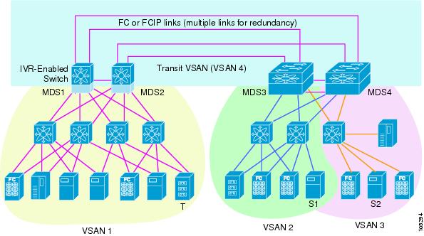
Figure 1-1 Traffic Continuity Using IVR and FCIP
IVR Terminology
The following IVR-related terms are used in the IVR documentation:
•
Native VSAN—The VSAN to which an end device logs on is the native VSAN for that end device.
•
Current VSAN—The VSAN currently being configured for IVR.
•
Inter-VSAN Routing zone (IVR zone)—A set of end devices that are allowed to communicate across VSANs within their interconnected SAN fabric. This definition is based on their port world-wide names (pWWNs) and their native VSAN associations. Prior to Cisco SAN-OS Release 3.0(3), you could configure up to 2000 IVR zones and 10,000 IVR zone members on the switches in the network. As of Cisco SAN-OS Release 3.0(3), you can configure up to 8000 IVR zones and 20,000 IVR zone members on the switches in the network.
•
Inter-VSAN routing zone sets (IVR zone sets)—One or more IVR zones make up an IVR zone set. You can configure up to 32 IVR zone sets on any switch in the Cisco MDS 9000 Family. Only one IVR zone set can be active at any time.
•
IVR path—An IVR path is a set of switches and Inter-Switch Links (ISLs) through which a frame from an end device in one VSAN can reach another end device in some other VSAN. Multiple paths can exist between two such end devices.
•
IVR-enabled switch—A switch on which the IVR feature is enabled.
•
Edge VSAN—A VSAN that initiates (source edge-VSAN) or terminates (destination edge-VSAN) an IVR path. Edge VSANs may be adjacent to each other or they may be connected by one or more transit VSANs. VSANs 1, 2, and 3 (see Figure 1-1), are edge VSANs.
Note
An edge VSAN for one IVR path can be a transit VSAN for another IVR path.
•
Transit VSAN—A VSAN that exists along an IVR path from the source edge VSAN of that path to the destination edge VSAN of that path. VSAN 4 is a transit VSAN (see Figure 1-1).
Note
When the source and destination edge VSANs are adjacent to each other, then a transit VSAN is not required between them.
•
Border switch—An IVR-enabled switch that is a member of two or more VSANs. Border switches, such as the IVR-enabled switch between VSAN 1 and VSAN 4 (see Figure 1-1), span two or more different color-coded VSANs.
•
Edge switch—A switch to which a member of an IVR zone has logged in to. Edge switches are unaware of the IVR configurations in the border switches. Edge switches do not need to be IVR-enabled.
•
Autonomous Fabric Identifier (AFID)—Allows you to configure more than one VSAN in the network with the same VSAN ID and avoid downtime when configuring IVR between fabrics that contain VSANs with the same ID.
•
Service group—Allows you to reduce the amount of IVR traffic to non-IVR-enabled VSANs by configuring one or more service groups that restrict the traffic to the IVR-enabled VSANs.
IVR Configuration Limits
Table 1-1 summarizes the configuration limits for IVR.
Table 1-1 IVR Configuration Limits
IVR Feature
|
Maximum Limit
|
IVR VSANs
|
128
|
IVR zone members
|
As of Cisco SAN-OS Release 3.0(3), 20,000 IVR zone members per physical fabric
Prior to Cisco SAN-OS Release 3.0(3), 10,000 IVR zone members per physical fabric
|
IVR zones
|
As of Cisco SAN-OS Release 3.0(3), 8000 IVR zones per physical fabric
Prior to Cisco SAN-OS Release 3.0(3), 2000 IVR zones per physical fabric
|
IVR zone sets
|
32 IVR zone sets per physical fabric
|
IVR service groups
|
16 service groups per physical fabric
|
IVR switches
|
25 (IVR auto topology mode)
Note We recommend IVR manual topology mode if you have more than 25 IVR switches. See "Manually Configuring an IVR Topology" on page 2-11.
|
IVR CFS Distribution
The IVR feature uses the Cisco Fabric Services (CFS) infrastructure to enable efficient configuration management and to provide a single point of configuration for the entire fabric in the VSAN. For information on CFS, refer to the Cisco MDS 9000 Family NX-OS System Management Configuration Guide.
The following configurations are distributed:
•
IVR zones
•
IVR zone sets
•
IVR VSAN topology
•
IVR active topology and zone set (activating these features in one switch propagates the configuration to all other distribution-enabled switches in the fabric)
•
AFID database
Database Implementation
The IVR feature uses three databases to accept and implement configurations.
•
Configured database—The database is manually configured by the user.
•
Active database—The database is currently enforced by the fabric.
•
Pending database—If you modify the configuration, you need to commit or discard the configured database changes to the pending database. The fabric remains locked during this period. Changes to the pending database are not reflected in the active database until you commit the changes to CFS.
Locking the Fabric
The first action that modifies the database creates the pending database and locks the feature in the VSAN. Once you lock the fabric, the following situations apply:
•
No other user can make any configuration changes to this feature.
•
A copy of the configuration database becomes the pending database along with the first active change.
Fibre Channel Header Modifications
IVR virtualizes the remote end devices in the native VSAN using a virtual domain. When IVR is configured to link end devices in two disparate VSANs, the IVR border switches are responsible for modifying the Fibre Channel headers for all communication between the end devices. The sections of the Fibre Channel frame headers that are modified include:
•
VSAN number
•
Source FCID
•
Destination FCID
When a frame travels from the initiator to the target, the Fibre Channel frame header is modified such that the initiator VSAN number is changed to the target VSAN number. If IVR Network Address Translation (NAT) is enabled, then the source and destination FCIDs are also translated at the edge border switch. If IVR NAT is not enabled, then you must configure unique domain IDs for all switches involved in the IVR path.
IVR Network Address Translation
IVR Network Address Translation (NAT) can be enabled to allow non-unique domain IDs; however, without NAT, IVR requires unique domain IDs for all switches in the fabric. IVR NAT simplifies the deployment of IVR in an existing fabric where non-unique domain IDs might be present.
To use IVR NAT, it must be enabled on all IVR-enabled switches in the fabric. By default, IVR NAT and IVR configuration distributions are disabled on all switches in the Cisco MDS 9000 Family.
See "Enabling IVR NAT and IVR Auto Topology Mode" on page 1-17 for information on IVR requirements and guidelines as well as configuration information.
IVR VSAN Topology
IVR uses a configured IVR VSAN topology to determine how to route traffic between the initiator and the target across the fabric.
IVR auto topology mode automatically builds the IVR VSAN topology and maintains the topology database when fabric reconfigurations occur. IVR auto topology mode also distributes the IVR VSAN topology to IVR-enabled switches using CFS.
Using IVR auto topology mode, you no longer need to manually update the IVR VSAN topology when reconfigurations occur in your fabric. If an IVR manual topology database exists, IVR auto topology mode initially uses that topology information. The automatic update reduces disruption in the network by gradually migrating from the user-specified topology database to the automatically-learned topology database. User-configured topology entries that are not part of the network are aged out in about three minutes. New entries that are not part of the user-configured database are added as they are discovered in the network.
When IVR auto topology mode is enabled, it starts with the previously active IVR manual topology if it exists, and then the discovery process begins. New, alternate, or better paths my be discovered. If the traffic is switched to an alternate or better path, there may be temporary traffic disruptions that are normally associated with switching paths.
Note
IVR topology in IVR auto topology mode requires Cisco MDS SAN-OS Release 2.1(1a) or later and CFS must be enabled for IVR on all switches in the fabric.
IVR Virtual Domains
In a remote VSAN, the IVR application does not automatically add the virtual domain to the assigned domains list. Some switches (for example, the Cisco SN5428 switch) do not query the remote name server until the remote domain appears in the assigned domains list in the fabric. In such cases, add the IVR virtual domains in a specific VSAN to the assigned domains list in that VSAN. When adding IVR domains, all IVR virtual domains that are currently present in the fabric (and any virtual domain that is created in the future) will appear in the assigned domains list for that VSAN.
Tip
Be sure to add IVR virtual domains if Cisco SN5428 or Cisco MDS 9020 switches exist in the VSAN.
When you enable the IVR virtual domains, links may fail to come up due to overlapping virtual domain identifiers. If this occurs, temporarily withdraw the overlapping virtual domain from that VSAN.
Note
Withdrawing an overlapping virtual domain from an IVR VSAN disrupts IVR traffic to and from that domain.
Tip
Only add IVR domains in the edge VSANs and not in transit VSANs.
IVR Zones
As part of the IVR configuration, you need to configure one or more IVR zones to enable cross-VSAN communication. To achieve this result, you must specify each IVR zone as a set of (pWWN, VSAN) entries. Like zones, several IVR zone sets can be configured to belong to an IVR zone. You can define several IVR zone sets and activate only one of the defined IVR zone sets.
Note
The same IVR zone set must be activated on all of the IVR-enabled switches.
Table 1-2 identifies the key differences between IVR zones and zones.
Table 1-2 Key Differences Between IVR Zones and Zones
IVR Zones
|
Zones
|
IVR zone membership is specified using the VSAN and pWWN combination.
|
Zone membership is specified using pWWN, fabric WWN, sWWN, or the AFID.
|
Default zone policy is always deny (not configurable).
|
Default zone policy is deny (configurable).
|
Automatic IVR Zone Creation
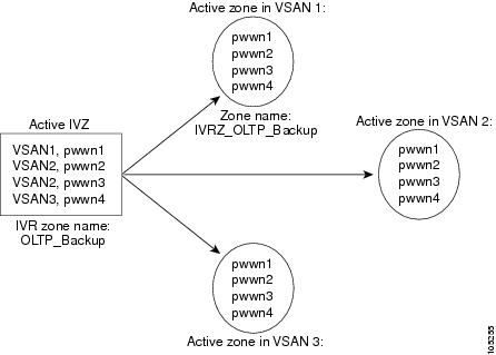
Figure 1-2 depicts an IVR zone consisting of four members. To allow pwwn1 to communicate with pwwn2, they must be in the same zone in VSAN 1, as well as in VSAN 2. If they are not in the same zone, then the hard-zoning ACL entries will prohibit pwwn1 from communicating with pwwn2.
A zone corresponding to each active IVR zone is automatically created in each edge VSAN specified in the active IVR zone. All pWWNs in the IVR zone are members of these zones in each VSAN.
Figure 1-2 Creating Zones Upon IVR Zone Activation
The zones are created automatically by the IVR process when an IVR zone set is activated. They are not stored in a full zone set database and are lost when the switch reboots or when a new zone set is activated. The IVR feature monitors these events and adds the zones corresponding to the active IVR zone set configuration when a new zone set is activated. Like zone sets, IVR zone sets are also activated nondisruptively.
Note
If pwwn1 and pwwn2 are in an IVR zone in the current as well as the new IVR zone set, then activation of the new IVR zone set does not cause any traffic disruption between them.
IVR zone and IVR zone set names are restricted to 64 alphanumeric characters.
Caution 
Prior to Cisco SAN-OS Release 3.0(3), you can only configure a total of 2000 IVR zones and 32 IVR zone sets on the switches in the network. As of Cisco SAN-OS Release 3.0(3), you can only configure a total of 8000 IVR zones and 32 IVR zone sets on the switches in the network. See
"Database Merge Guidelines" on page 1-11.
IVR Interoperability
When using the IVR feature, all border switches in a fabric must be Cisco MDS switches. However, other switches in the fabric may be non-MDS switches. For example, end devices that are members of the active IVR zone set may be connected to non-MDS switches. Non-MDS switches may also be present in the transit VSAN(s) or in the edge VSANs if one of the interop modes is enabled.
For additional information on switch interoperability, refer to the Cisco Data Center Interoperability Support Matrix.
Guidelines and Limitations
This section includes the following topics:
•
IVR NAT Requirements and Guidelines
•
IVR Zone Limits and Image Downgrading Guidelines
•
Database Merge Guidelines
IVR NAT Requirements and Guidelines
IVR NAT has the following requirements and guidelines:
•
All IVR-enabled switches must run Cisco MDS SAN-OS Release 2.1(1a) or later.
•
IVR NAT port login (PLOGI) requests that are received from hosts are delayed a few seconds to perform the rewrite on the FC ID address. If the host's PLOGI timeout value is set to a value less than five seconds, it may result in the PLOGI being unnecessarily aborted and the host being unable to access the target. We recommend that you configure the host bus adapter for a timeout of at least ten seconds (most HBAs default to a value of 10 or 20 seconds).
•
IVR NAT requires Cisco MDS SAN-OS Release 2.1(1a) or later on all IVR switches in the fabric. If you have isolated switches with an earlier release that are configured in an IVR topology, you must remove any isolated fabrics from being monitored by the DCNM-SAN and then re-open the fabric to use IVR NAT. See the Cisco DCNM Fundamentals Guide for information on selecting a fabric to manage continuously.
•
Load balancing of IVR NAT traffic across equal cost paths from an IVR-enabled switch is not supported. However, load balancing of IVR NAT traffic over PortChannel links is supported. The load-balancing algorithm for IVR NAT traffic over PortChannel with Generation 1 modules is SRC/DST only. Generation 2 modules support SRC/DST/OXID-based load balancing of IVR NAT traffic across a PortChannel.
•
You cannot configure IVR NAT and preferred Fibre Channel routes on Generation 1 module interfaces.
•
IVR NAT allows you to set up IVR in a fabric without needing unique domain IDs on every switch in the IVR path. IVR NAT virtualizes the switches in other VSANs by using local VSAN for the destination IDs in the Fibre Channel headers. In some Extended Link Service message types, the destination IDs are included in the packet data. In these cases, IVR NAT replaces the actual destination ID with the virtualized destination ID. IVR NAT supports destination ID replacement in the Extended Link Service messages described in Table 1-3.
Table 1-3 Extended Link Service Messages Supported by IVR NAT
Extended Link Service Messages
|
Link Service Command (LS_COMMAND)
|
Mnemonic
|
Abort Exchange
|
0x06 00 00 00
|
ABTX
|
Discover Address
|
0x52 00 00 00
|
ADISC
|
Discover Address Accept
|
0x02 00 00 00
|
ADISC ACC
|
Fibre Channel Address Resolution Protocol Reply
|
0x55 00 00 00
|
FARP-REPLY
|
Fibre Channel Address Resolution Protocol Request
|
0x54 00 00 00
|
FARP-REQ
|
Logout
|
0x05 00 00 00
|
LOGO
|
Port Login
|
0x30 00 00 00
|
PLOGI
|
Read Exchange Concise
|
0x13 00 00 00
|
REC
|
Read Exchange Concise Accept
|
0x02 00 00 00
|
REC ACC
|
Read Exchange Status Block
|
0x08 00 00 00
|
RES
|
Read Exchange Status Block Accept
|
0x02 00 00 00
|
RES ACC
|
Read Link Error Status Block
|
0x0F 00 00 00
|
RLS
|
Read Sequence Status Block
|
0x09 00 00 00
|
RSS
|
Reinstate Recovery Qualifier
|
0x12 00 00 00
|
RRQ
|
Request Sequence Initiative
|
0x0A 00 00 00
|
RSI
|
Scan Remote Loop
|
0x7B 00 00 00
|
RSL
|
Third Party Process Logout
|
0x24 00 00 00
|
TPRLO
|
Third Party Process Logout Accept
|
0x02 00 00 00
|
TPRLO ACC
|
•
If you have a message that is not recognized by IVR NAT and contains the destination ID in the packet data, you cannot use IVR with NAT in your topology. You can still use IVR with unique domain IDs.
Transit VSAN Guidelines
Consider the following guidelines for transit VSANs:
•
In addition to defining the IVR zone membership, you can choose to specify a set of transit VSANs to provide connectivity between two edge VSANs:
–
If two edge VSANs in an IVR zone overlap, then a transit VSAN is not required (though, not prohibited) to provide connectivity.
–
If two edge VSANs in an IVR zone do not overlap, you may need one or more transit VSANs to provide connectivity. Two edge VSANs in an IVR zone will not overlap if IVR is not enabled on a switch that is a member of both the source and destination edge VSANs.
•
Traffic between the edge VSANs only traverses through the shortest IVR path.
•
Transit VSAN information is common to all IVR zone sets. Sometimes, a transit VSAN can also act as an edge VSAN in another IVR zone.
Border Switch Guidelines
Before configuring border switches, consider the following guidelines:
•
Border switches require Cisco MDS SAN-OS Release 2.1(1a) or later.
•
A border switch must be a member of two or more VSANs.
•
A border switch that facilitates IVR communsications must be IVR-enabled.
•
IVR can (optionally) be enabled on additional border switches to provide redundant paths between active IVR zone members.
•
The VSAN topology configuration updates automatically when a border switch is added or removed.
IVR Zone Limits and Image Downgrading Guidelines
Table 1-4 identifies the IVR zone limits per physical fabric.
Table 1-4 IVR Zone Limits
Cisco Release
|
IVR Zone Limit
|
IVR Zone Member Limit
|
IVR Zone Set Limit
|
SAN-OS Release 3.0(3 or later
|
8000
|
20,000
|
32
|
SAN-OS Release 3.0(2b) or earlier
|
2000
|
10,000
|
32
|
Note
A zone member is counted twice if it exists in two zones. See "Database Merge Guidelines" on page 1-11.
Caution 
If you want to downgrade to a release prior to Cisco SAN-OS Release 3.0(3), the number of IVR zones cannot exceed 2000 and the number of IVR zone members cannot exceed 10,000.
Database Merge Guidelines
A database merge refers to the combination of the configuration database and static (unlearned) entries in the active database. For information on CFS merge support, refer to the Cisco MDS 9000 Family NX-OS System Management Configuration Guide or System Management Configuration Guide, Cisco DCNM for SAN.
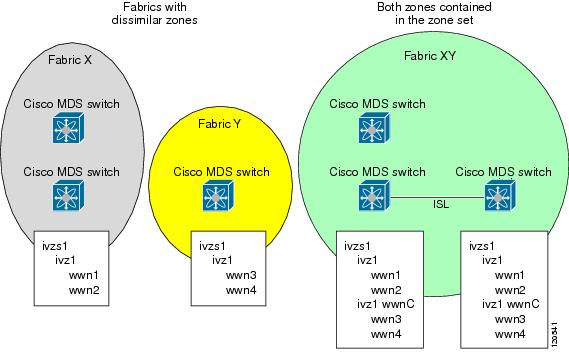
Consider the following guidelines when merging two IVR fabrics:
•
The IVR configurations are merged even if two fabrics contain different configurations.
•
If dissimilar zones exist in two merged fabrics, the zone from each fabric is cloned in the distributed zone set with appropriate names (see Figure 1-3).
Figure 1-3 Fabric Merge Consequences
•
You can configure different IVR configurations in different Cisco MDS switches.
•
To avoid traffic disruption, after the database merge is complete, the configuration is a combination of the configurations that were present on the two switches involved in the merge.
–
The configurations are merged even if both fabrics have different configurations.
–
A combination of zones and zone sets are used to get the merged zones and zone sets. If a dissimilar zone exists in two fabrics, the dissimilar zones are cloned into the zone set with appropriate names so both zones are present.
–
The merged topology contains a combination of the topology entries for both fabrics.
–
The merge will fail if the merged database contains more topology entries than the allowed maximum.
–
The total number of VSANs across the two fabrics cannot exceed 128.
Note
VSANs with the same VSAN ID but different AFIDs are counted as two separate VSANs.
–
The total number of IVR-enabled switches across the two fabrics cannot exceed 128.
–
The total number of zone members across the two fabrics cannot exceed 10,000. As of Cisco SAN-OS Release 3.0(3), the total number of zone members across the two fabrics cannot exceed 20,000. A zone member is counted twice if it exists in two zones.
Note
If one or more of the fabric switches are running Cisco SAN-OS Release 3.0(3) or later, and the number of zone members exceeds 10,000, you must either reduce the number of zone members in the fabric or upgrade all switches in both fabrics to Cisco SAN-OS Release 3.0(3) or later.
–
The total number of zones across the two fabrics cannot exceed 2000. As of Cisco SAN-OS Release 3.0(3), the total number of zones across the two fabrics cannot exceed 8000.
Note
If only some of the switches in the fabrics are running Cisco SAN-OS Release 3.0(3) or later, and if the number of zones exceeds 2000, you must either reduce the number of zones in the fabric or upgrade all switches in both fabrics to Cisco SAN-OS Release 3.0(3) or later.
–
The total number or zone sets across the two fabrics cannot exceed 32.
Table 1-5 describes the results of a CFS merge of two IVR-enabled fabrics under different conditions.
Table 1-5 Results of Merging Two IVR-Enabled Fabrics
IVR Fabric 1
|
IVR Fabric 2
|
After Merge
|
NAT enabled
|
NAT disabled
|
Merge succeeds and NAT is enabled
|
Auto mode enabled
|
Auto mode disabled
|
Merge succeeds and IVR auto topology mode is enabled
|
Conflicting AFID database
|
Merge fails
|
Conflicting IVR zone set database
|
Merge succeeds with new zones created to resolve conflicts
|
Combined configuration exceeds limits (such as maximum number of zones or VSANs)
|
Merge fails
|
Service group 1
|
Service group 2
|
Merge succeeds with service groups combined
|
User-configured VSAN topology configuration with conflicts
|
Merge fails
|
User-configured VSAN topology configuration without conflicts
|
Merge succeeds
|
Caution 
If you do not follow these conditions, the merge will fail. The next distribution will forcefully synchronize the databases and the activation states in the fabric.
Default Settings
Table 1-6 lists the default settings for IVR parameters.
Table 1-6 Default IVR Parameters
Parameters
|
Default
|
IVR feature
|
Disabled
|
IVR VSANs
|
Not added to virtual domains
|
IVR NAT
|
Disabled
|
QoS for IVR zones
|
Low
|
Configuration distribution
|
Disabled
|
Configuring Basic Inter-VSAN Routing
This section includes the following topics:
•
Task Flow for Configuring Basic Inter-VSAN Routing
•
Configuring IVR and IVR Zones Using the IVR Zone Wizard
•
Enabling IVR
•
Distributing the IVR Configuration Using CFS
•
Enabling IVR NAT and IVR Auto Topology Mode
•
Configuring IVR Zones and IVR Zone Sets
•
Activating Zone Sets and Using the force Option
•
Activating or Deactivating IVR Zone Sets
•
Configuring IVR Logging Severity Levels
Task Flow for Configuring Basic Inter-VSAN Routing
To configure basic IVR, follow these steps:
Configuring IVR and IVR Zones Using the IVR Zone Wizard
The IVR Zone Wizard simplifies the process of configuring IVR zones in a fabric. The IVR Zone Wizard checks the following conditions and identifies any related issues:
•
Checks all switches in the fabric to identify the Cisco SAN-OS or NX-OS release that is running on the switch. If Cisco MDS SAN-OS Release 2.1(1a) or later is running on the switch, you can decide to migrate to IVR NAT with IVR auto topology mode.
•
Checks all switches in the fabric to identify the Cisco SAN-OS or NX-OS release that is running on the switch. If Cisco MDS SAN-OS Release 2.1(1a) or later is running on a switch, you can decide to upgrade the switch or disable IVR NAT or IVR auto topology mode if they are enabled.
Detailed Steps
To configure IVR and IVR zones using the IVR Zone Wizard, follow these steps:
Step 1
Click the IVR Zone Wizard icon in the Zone toolbar.
To migrate to IVR NAT mode click Yes, otherwise, click No. You see the IVR Zone Wizard dialog box.
Step 2
Select the VSANs that will participate in IVR in the fabric. Click Next.
Step 3
Select the end devices that you want to connect using IVR.
Note
If you are not using IVR NAT, DCNM for SAN might display an error message if all the switches participating in IVR do not have unique domain IDs. You must reconfigure those switches before configuring IVR. See Step 6.
Step 4
If you enable IVR NAT, verify which switches that DCNM-SAN will enable with IVR NAT, CFS for IVR, and IVR auto topology mode.
Step 5
Enter the VSAN ID of the VSAN that you want to use as the transit VSAN between the VSANs selected for the IVR zone. Click Next.
Step 6
(Optional) Configure a unique AFID for switches in the fabric that have non-unique VSAN IDs in the Select AFID dialog box.
Step 7
If you did not enable IVR NAT, verify the transit VSAN or configure the transit VSAN if DCNM-SAN cannot find an appropriate transit VSAN.
Step 8
Set the IVR zone and IVR zone set.
Step 9
Verify all steps that DCNM-SAN will take to configure IVR in the fabric.
Step 10
Click Finish if you want to enable IVR NAT and IVR auto topology mode and to create the associated IVR zones and IVR zone set.
You see the Save Configuration dialog box. You can save the configuration of the master switch to be copied to other IVR-enabled switches.
Step 11
Click Continue Activation, or click Cancel.
Step 12
Click Finish.
Note
IVR NAT and IVR auto topology mode can be configured independently if you configure these features outside the IVR Zone Wizard. See "Configuring Basic Inter-VSAN Routing" on page 1-14.
Enabling IVR
The IVR feature must be enabled in all border switches in the fabric that participate in the IVR. By default, this feature is disabled in all Cisco MDS 9000 Family switches. You can manually enable IVR on all required switches in the fabric or configure fabric-wide distribution of the IVR configuration. See "Distributing the IVR Configuration Using CFS" on page 1-16.
The configuration and verification commands for the IVR feature are only available when IVR is enabled on a switch. When you disable this configuration, all related configurations are automatically discarded.
Distributing the IVR Configuration Using CFS
IVR configuration distribution is disabled by default. For the feature to function correctly, you must enable it on all IVR-enabled switches in the network.
This section includes the following topics:
•
Committing the Changes
•
Discarding the Changes
•
Clearing a Locked Session
Committing the Changes
If you commit the changes made to the active database, the configuration is committed to all the switches in the fabric. On a successful commit, the configuration change is applied throughout the fabric and the lock is released.
Discarding the Changes
If you discard (abort) the changes made to the pending database, the configuration database remains unaffected and the lock is released.
Clearing a Locked Session
If you have performed an IVR task and have forgotten to release the lock by either committing or discarding the changes, an administrator can release the lock from any switch in the fabric. If the administrator performs this task, your changes to the pending database are discarded and the fabric lock is released.
Tip
The pending database is only available in the volatile directory and is subject to being discarded if the switch is restarted.
Enabling IVR NAT and IVR Auto Topology Mode
This section describes how to enable IVR NAT and how to enable IVR auto topology mode.
Prerequisites
Before configuring an IVR SAN fabric to use IVR NAT and IVR auto topology mode, consider the following:
•
Configure IVR only in the relevant switches.
•
Enable CFS for IVR on all switches in the fabric. You must first click the CFS tab in order for the other tabs on the dialog boxes to become available.
•
Verify that all switches in the fabric are running Cisco MDS SAN-OS Release 2.1(1a) or later.
•
Acquire a mandatory Enterprise License Package or SAN-EXTENSION license package if you have Cisco MDS SAN-OS Release 2.1(1a) or later and one active IPS card for this feature. For information on licensing, refer to the Cisco MDS 9000 Family NX-OS Licensing Guide.
•
Enable IVR configuration distribution before configuring IVR auto topology mode (see "Distributing the IVR Configuration Using CFS" on page 1-16). Once IVR auto topology mode is enabled, you cannot disable IVR configuration distribution.
Restrictions
•
If you change any FSPF link cost, ensure that the FSPF path distance (that is, the sum of the link costs on the path) of any IVR path is less than 30,000.
•
The IVR over FCIP feature is bundled with the Cisco MDS 9216i Switch and does not require the SAN extension over IP package for the fixed IP ports on the supervisor module.
•
IVR-enabled VSANs can be configured when the interop mode is enabled (any interop mode) or disabled (no interop mode).
Detailed Steps
To enable IVR NAT and IVR auto topology mode, follow these steps:
Step 1
Expand All VSANs and then select IVR in the Logical Domains pane.
You see the inter-VSAN routing configuration in the Information pane.
Step 2
Select Enable from the Admin column drop-down menu for the primary switch.
Step 3
Click the Apply Changes icon to distribute this change to all switches in the fabric.
Step 4
Click the Action tab.
Step 5
Check the Enable IVR NAT check box to enable IVR in NAT mode.
Step 6
Check the Auto Discover Topology check box to enable IVR auto topology mode.
Step 7
Click the Apply Changes icon to enable IVR on the switches.
Configuring IVR Zones and IVR Zone Sets
Restrictions
•
Do not create a zone with the prefix IVRZ or a zone set with the name nozoneset. These names are created by the system and they are used for identifying IVR zones.
Detailed Steps
To create IVR zones and IVR zone sets, follow these steps:
Step 1
Choose Zone > IVR > Edit Local Full Zone Database.
You see the Edit IVR Local Full Zone Database dialog box for the selected VSAN.
If you want to view zone membership information, right-click in the Members column, and then click Show Details for the current row or all rows from the pop-up menu.
Step 2
Click Zones in the left pane and click the Insert icon to create a zone.
You see the Create IVR Zone dialog box.
Step 3
Enter an IVR zone name.
Step 4
Check one of the following check boxes:
a.
Read Only—The zone permits read and denies write.
b.
Permit QoS traffic with Priority—You set the priority from the drop-down menu.
Step 5
Click OK to create the IVR zone.
Step 6
To add members to this zone, select the members you want to add from the Fabric pane and click Add to Zone.
Step 7
Alternatively, click the zone where you want to add members and click the Insert icon.
You see the Add Member to Zone dialog box.
Step 8
If you added a zone set, select the new zone set and then click Activate.
You see the Save Configuration dialog box.
Step 9
Check the Save Running to Startup Configuration check box to save all changes to the startup configuration.
Step 10
Click Continue Activation to activate the zone set.
Note
Sometimes zone names beginning with the prefix IVRZ and a zone set with the name nozoneset appear in a logical view. The zones with the prefix IVRZ are IVR zones that get appended to regular active zones. The prefix IVRZ is appended to active IVR zones by the system. Similarly, the zone set with the name nozoneset is an IVR active zone set created by the system if no active zone set is available for that VSAN and if the ivrZonesetActivateForce flag is enabled on the switch.
In the server.properties file, you can set the property zone.ignoreIVRZones to true or false to either hide or view IVR zones as part of regular active zones. For information on the server.properties file, refer to the Cisco DCNM Fundamentals Configuration Guide.
Step 11
Select the new zone or zone set from the list in the Information pane, and then click Distribute.
Configuring IVR Zone with IVR CFS Regions
Detailed Steps
To create IVR zone with IVR CFS regions, follow these steps:
Step 1
Enable IVR on all the switches.
An IVR CFS region should not be configured on the IVR-enabled switches at this point.
Step 2
Choose Zone > IVR > Edit Local Full Zone Database.
You see the Edit IVR Local Full Zone Database dialog box for the selected VSAN.
Step 3
From the Regions drop-down menu, select the IVR Region ID.
Only the IVR-enabled switches should be included in these regions.
Step 4
In the left pane, click Zones and click the Insert icon to create a zone.
You see the Create IVR Zone dialog box.
Step 5
Enter an IVR zone name.
Step 6
Check one of the following check boxes:
a.
Read Only—The zone permits read and denies write.
b.
Permit QoS traffic with Priority—You set the priority from the drop-down menu.
Step 7
Click OK to create the IVR zone.
Step 8
To add members to this zone, select the members you want to add from the Fabric pane and click Add to Zone.
Step 9
Alternatively, click the zone where you want to add members and click the Insert icon.
You see the Add Member to Zone dialog box.
Step 10
If you added a zone set, select the new zone set and then click Activate.
You see the Save Configuration dialog box.
Step 11
Check the Save Running to Startup Configuration check box to save all changes to the startup configuration.
Step 12
Click Continue Activation to activate the zone set.
Note
If the activation is performed on a switch with a CFS region ID, complete the activation on a single switch with commit. You can verify the activation status through SNMP trace.
If switches in a configured IVR CFS region do not have CFS enabled, you will receive an error message on activation.
Configuring IVR CFS Regions with Enforced IVR Zone Set
Detailed Steps
To create an IVR zone with IVR CFS regions, follow these steps:
Step 1
Enable IVR on all the switches.
An IVR CFS region should not be configured on the IVR-enabled switches at this point.
Step 2
Choose Zone > IVR > Edit Local Full Zone Database.
You see the Edit IVR Local Full Zone Database dialog box for the selected VSAN.
Step 3
From the Regions drop-down menu, select the IVR Region ID.
Only the IVR-enabled switches should be included in these regions.
Step 4
In the left pane, click Zones and click the Insert icon to create a zone.
You see the Create IVR Zone dialog box.
Step 5
Create enforced IVR zones for each region.
The logical pane VSAN tree shows a node for each enforced zone set per region under the IVR tree node. When you click the enforced zone tree node, the table in the right pane shows the enforced zones and zone members for the relevant IVR CFS region. If zones in a region are either activated or deactivated, the VSAN tree dynamically updates itself.
Activating Zone Sets and Using the force Option
Once the zone sets have been created and populated, you must activate the zone set. When you activate an IVR zone set, IVR automatically adds an IVR zone to the regular active zone set of each edge VSAN. If a VSAN does not have an active zone set, IVR can only activate an IVR zone set using the force option, which causes IVR to create an active zone set called "nozoneset" and adds the IVR zone to that active zone set.
Caution 
If you deactivate the regular active zone set in a VSAN, the IVR zone set is also deactivated. This occurs because the IVR zone in the regular active zone set, and all IVR traffic to and from the switch, is stopped. To reactivate the IVR zone set, you must reactivate the regular zone set.
Note
If IVR and iSLB are enabled in the same fabric, at least one switch in the fabric must have both features enabled. Any zoning-related configuration or activation operation (for normal zones, IVR zones, or iSLB zones) must be performed on this switch. Otherwise, traffic might be disrupted in the fabric.
You can also use the force activate option to activate IVR zone sets. Table 1-7 lists the various scenarios with and without the force activate option.
Table 1-7 IVR Scenarios with and without the Force Activate Option
Case
|
Default Zone Policy
|
Active Zone Set before IVR Zone Activation
|
Force Activate
Option Used?
|
IVR Zone Set Activation Status
|
Active IVR Zone Created?
|
Possible Traffic Disruption
|
1
|
Deny
|
No active zone set
|
No
|
Failure
|
No
|
No
|
2
|
Yes
|
Success
|
Yes
|
No
|
31
|
Deny
|
Active zone set present
|
No/Yes
|
Success
|
Yes
|
No
|
4
|
Permit
|
No active zone set or Active zone set present
|
No
|
Failure
|
No
|
No
|
5
|
Yes
|
Success
|
Yes
|
Yes
|
Caution 
Using the
force activate option of IVR zone set activation may cause traffic disruption, even for devices that are not involved in IVR. For example, if your configuration does not have any active zone sets and the default zone policy is permit, then an IVR zone set activation will fail. However, IVR zone set activation will be successful if the
force activate option is used. Because zones are created in the edge VSANs corresponding to each IVR zone, traffic may be disrupted in edge VSANs where the default zone policy is permit.
Activating or Deactivating IVR Zone Sets
Restrictions
•
To replace the active IVR zone set with a new IVR zone set without disrupting traffic, activate the new IVR zone set without deactivating the current active IVR zone set.
Detailed Steps
To activate or deactivate an existing IVR zone set, follow these steps:
Step 1
Click Zone and then select Edit Local Full Zone Database.
You see the Edit Local Full Zone Database dialog box.
Step 2
Select a Zoneset folder, and then click Activate to activate the zone set or click Deactivate to deactivate an activated zone set.
You see the Save Configuration dialog box.
Step 3
(Optional) Check one of the Save Running to Configuration check boxes to save these changes to the startup configuration.
Step 4
Click Continue Activation to activate the zone set or Yes if you are deactivating the zone set.
Note
If you make any changes to the full zone set that results in a difference between the active zone set and full zone set, the active zone set in Edit Zone is shown in bold. Activating the zone set, unbolds it.
Configuring IVR Logging Severity Levels
You can configure Telnet or SSH logging for the IVR feature. For example, if you configure the IVR logging level at level 4 (warning), then messages with a severity level of 4 or above are displayed. Use the instructions in this section to configure the logging levels.
Detailed Steps
To configure the severity level for logging messages from the IVR feature, follow these steps:
Step 1
Expand Switches > Events, and then select Syslog from the Physical Attributes pane.
Step 2
Click the Severity Levels tab.
Step 3
Click the Facility column header to sort the table by facility name.
Step 4
Select the severity level at which the IVR logs system messages from the Severity drop-down menu.
Tip
Setting the severity to warning means that all IVR messages at the warning level or above will be logged to DCNM-SAN.
Step 5
Click the Apply Changes icon to save these changes locally.
Monitoring Basic Inter-VSAN Routing Configuration
This section includes the following topics:
•
Clearing an IVR fcdomain Database
•
Recovering an IVR Full Zone Database
•
Recovering an IVR Topology
•
Resolving Database Merge Failures
Clearing an IVR fcdomain Database
Detailed Steps
To manually configure an IVR virtual domain, follow these steps:
Step 1
Expand All VSANs and then select IVR in the Logical Domains pane.
You see the IVR configuration in the Information pane.
Step 2
Click the Domains tab to display the existing IVR topology.
Step 3
Click the Create Row icon to create rows in the IVR topology.
Step 4
Enter the Current Fabric, Current VSAN, Native Fabric, Native VSAN and Domain ID in the dialog box. These are the VSANs that will add the IVR virtual domains to the assigned domains list.
Step 5
Click Create to create this new row.
Recovering an IVR Full Zone Database
You can recover an IVR zone database by copying the IVR full zone database from another switch.
Detailed Steps
To recover an IVR zone database, follow these steps:
Step 1
Choose Zone > IVR > Edit Local Full Zone Database.
You see the Edit IVR Local Full Zone Database dialog box.
Step 2
Choose Edit > Copy Full Zone Database.
You see the Copy Full Zone Database dialog box.
Step 3
Choose either Active or Full, depending on which type of IVR database you want to copy.
Step 4
Select the source switch from which to copy the information from the drop-down list.
Step 5
Select the destination switch from the drop-down list.
Step 6
Click Copy to copy the database.
Recovering an IVR Topology
You can recover a topology by copying the active zone database or the full zone database.
Detailed Steps
To recover a zone topology, follow these steps:
Step 1
Choose Zone > IVR > Edit Local Full Zone Database.
You see the Edit IVR Local Full Zone Database dialog box.
Step 2
Choose Edit > Copy Full Topology.
You see the Copy Full Topology dialog box.
Step 3
Choose either Active or Full, depending on which type of IVR database you want to copy from.
Step 4
Select the source switch from which to copy the information from the drop-down list.
Step 5
Select the destination switch from the drop-down list.
Step 6
Click Copy to copy the topology.
Resolving Database Merge Failures
If a merge failure occurs, you can use the following CLI commands to display the error conditions:
•
show ivr merge status
•
show cfs merge status name ivr
•
show logging last lines (and look for MERGE failures)
To resolve merge failures, review the failure information indicated in the show command outputs, then find the scenario in this list that relates to the failure and follow the troubleshooting instructions:
•
If the failure is due to exceeding the maximum configuration limits in a fabric where the switches are running more than one Cisco SAN-OS or NX-OS release, then either upgrade the switches running the earlier release or reduce the number of IVR zones and IVR zone members on the switches running the more recent release to the earlier release limit (see "IVR Configuration Limits" on page 1-4).
•
If the failure is due to exceeding maximum limits in a fabric where all switches are running the same Cisco SAN-OS or NX-OS release, identify the switch that has the correct configuration and perform a CFS commit to distribute the IVR configuration. See "Distributing the IVR Configuration Using CFS" on page 1-16 and "Autonomous Fabric IDs" on page 2-2.
•
For other failures, resolve the error causing the merge failure on the switch that has the correct configuration and perform a CFS commit to distribute the IVR configuration. See "Distributing the IVR Configuration Using CFS" on page 1-16 and "Autonomous Fabric IDs" on page 2-2.
Note
After a successful CFS commit, the merge will be successful.
Where to Go Next
After setting up a basic IVR configuration, see Chapter 2, "Configuring Advanced Inter-VSAN Routing," if you need to set up any advanced IVR configurations.