Table Of Contents
Out of Scope for this Document
Best Practices and Known Limitations
Security Concepts—Implementation and Configuration
Infrastructure Protection Mechanisms
Encryption Services (VPN Topology)
High Availability (Redundancy)
Redundant Multi-Threaded in a Single Site Location
Multiple Single-Threaded Site Locations of NGWAN Edge
QoS for WAN Aggregation Routers
Routing Protocol Implementation
Performance and Scalability Considerations
Hardware Crypto Acceleration is Required
VPN Topology and Routing Protocol Design
Level and Type of Logging of Security Mechanisms
Profile 1—Full Configuration for Cisco 7200VXR Crypto Aggregation Routers
Profile 1—Full Configuration for Cisco 7301 WAN Routers
Profile 1—Configuration for Cisco ASA 5540s
Profile 2—Full Configuration for Cisco 7200VXR Integrated-Crypto Aggregation and WAN Systems
Profile 2—Full Configuration for Cisco ASA 5540
Profile 3—Full Configuration for Cisco 7600 Crypto Aggregation System
Profile 3—Full Configuration for Cisco 7304 WAN Router
Profile 3—Configuration for Cisco Firewall Service Modules
Profile 4—Full Configuration for Cisco 7600 Crypto Aggregation and WAN System
Profile 4—Full Configuration for Cisco Firewall Service Module
L2 Switch Configurations for all Profiles
All Profiles—Full Configuration for Cisco Catalyst 3560 Switch (Used Mainly as L2 Switch)
Appendix A—Other Possible Topologies
Request For Comment (RFC) Papers
Infrastructure Protection and Security Service Integration Design for the Next Generation WAN Edge v2.0
Modern WAN architectures require additional network capabilities to support current higher bandwidth and mission-critical applications. Requirements for deploying voice over IP (VoIP) and video conferencing include high availability, IP multicast, and quality of service (QoS). Today, most enterprises rely on private WAN connections such as Frame Relay, ATM, or leased-line services to connect their businesses. When deploying a traditional Frame Relay or ATM-based private WAN, however, network operations must implement point-to-point or hub-and-spoke architectures that make provisioning and management of moves, adds, or changes on the network complex. Also, the operational expense for a private WAN can sometimes be higher than IP-based WAN technologies. The goal is to have reliable connectivity that is secure, can be easily updated, and can scale to meet evolving business needs.
To address these needs, Cisco provides validated, extensible network architectures that are underpinned by a comprehensive line of services aggregation routers. The portfolio of WAN solutions enables an enterprise to rapidly introduce new business applications and services from the branch office, through the campus, to the data center, while reducing operating costs and network complexity.
This design guide extends the portfolio of WAN solutions to provide a highly available, secure network design to the WAN edge. Providing the WAN architecture with security from outside attacks as well as protecting the traffic entering or exiting the WAN network is the focus of this design guide. This design guide defines the comprehensive functional components required to secure the infrastructure and data paths for an enterprise WAN edge.
Cisco Enterprise Systems Engineering (ESE) is dedicated to producing high-quality tested design guides that are intended to help deploy the system of solutions more confidently and safely. This design guide is part of an ongoing series that addresses enterprise WAN solutions using the latest advanced services technologies from Cisco and based on best practice design principles that have been tested in an enterprise systems environment.
Contents
Introduction
This design guide evaluates the securing of an enterprise WAN edge network as it pertains to the Cisco enterprise WAN and MAN architectures. These architectures are defined in detail at the following URL: http://www.cisco.com/en/US/netsol/ns817/networking_solutions_program_home.html.
The following four architectures were established to provide reliable connectivity to your global enterprise while reducing operational expenses, becoming more resilient, and enabling some of the latest network services:
•
Encrypted private connectivity—Takes advantage of existing traditional private WAN and MAN connections
•
•
•
These four architectures offer several secure alternatives to traditional private WAN connectivity that help increase network scalability and flexibility.
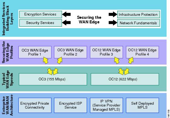
This design guide focuses only on the enterprise WAN edge network. The enterprise WAN edge is defined as the set of networking devices that aggregate traffic from enterprise branch offices, and pass that traffic to the enterprise campus or data center. Regardless of which enterprise WAN/MAN architecture is chosen, it is crucial to guarantee the devices and traffic residing at the WAN edge. This design guide examines two typical WAN edge speeds, OC3 (155 Mbps) and OC12 (622 Mbps), and establishes profiles for each WAN speed. These profiles are not intended to be the only recommended design architectures for the WAN edge. They are meant to show examples based on the majority of enterprise WAN edge architectures available today. Each profile provides guidelines for securing the WAN edge including infrastructure protection mechanisms, network fundamentals such as routing and high availability, and, finally, the security services needed to protect against threats to the WAN edge. The framework for this document is shown in Figure 1.
Figure 1 Enterprise WAN Edge Network Framework
This design guide begins with an overview followed by design recommendations. In addition, configuration examples are presented. Each service is described in detail and then shown in each of the various profiles to provide complete guidance on how to tackle securing a WAN edge network. You must have a basic understanding of all the following to successfully implement the concepts shown in this document:
•
•
•
•
•
•
Target Audience
This design guide is targeted for Cisco systems engineers and customer support engineers to provide guidelines and best practices for customer deployments.
Scope of Work
This version of the design guide addresses the following applications of the secure NGWAN edge solution:
•
–
–
–
–
•
–
•
–
–
–
–
•
–
–
•
Out of Scope for this Document
Cisco devices incorporate a wide variety of security services and mechanisms designed to protect the network infrastructure and attached host. This version of this document does not cover the following security-related features at this time:
•
•
•
•
•
•
Design Overview
This section provides a high-level overview of concepts to secure an enterprise WAN edge. Design and Implementation provides more detail on the design considerations, while Scalability Considerations presents primary considerations to be considered before deploying the design for scalability.
A network engineer and a security engineer are usually at odds when it comes to network security. They generally have conflicting goals. The network engineer is trying to connect users with services at the highest possible speed with as little intervention into the actual traffic as possible, while the security engineer is trying to secure the network from both network intrusions (restricting access to services) as well as providing protection to the network itself from DoS-type attacks that rob the infrastructure of valuable uptime. All network security can be summarized is a trade-off of simplicity and efficiency for a level of security and protection. The high-level goal of the security engineer is to achieve these layers of security at the lowest cost to the infrastructure (bandwidth, CPU utilization, and packet delay) as possible.
When choosing which security services and infrastructure protections are right for a customer, it is strongly recommended that customers perform a risk versus cost analysis. This leads to a monetary baseline that a service disruption (down or degraded time) would incur. A "dollar per minute unavailable" value helps in choosing the proper amount of layers and mechanisms that are appropriate for the customer. The customer should compute the amount of monies lost, computed as lost development time, possible PR fallout, legal fees, lost revenue (transactions), and so on, if a network intrusion occurred that yielded proprietary data being made public or consumed by the competition. These values of monies lost help the customer and the Cisco sales engineer decide which of the possible security features are required, explain to management the cost justifications of buying security gear, and assist in the staffing requirements for security enabling the enterprise WAN edge.
Under normal operating conditions, the legitimate end user network traffic consumes some, if not most, of the network resources (bandwidth, CPU utilization, forwarding capacity, and so on) as packets of the end user pass through the network devices. In the event of a DoS attack, a packet, or series of packets, are sent in the attempt to consume those network resources and keep the network from processing the legitimate traffic; thus, denying the legitimate user traffic the services it requires. The goals of infrastructure protection are to limit intrusions, prevent data/service theft, and to minimize the likelihood of success and mitigate the damage caused by DoS attacks. Infrastructure protection includes device hardening to secure the network devices from unauthorized access by non-solution administrators over various communication protocols, as well as mechanisms to control the use of CPU and memory resources.
This document describes some infrastructure protection features embedded in Cisco IOS and some Cisco firewalls, and also the integration of some key security services namely IPsec VPNs and firewalls. This document provides design guidance on enabling and integrating these protections and services on a single network device. It is not intended to be an exhaustive technical review of all nuances of the features, but rather how to implement them in a layered approach to provide a cohesive security solution for the NG WAN edge.
Some alternate barrier (firewall) locations and the ramification to security, performance, and connectivity are discussed in detail in Appendix A—Other Possible Topologies.
The security features described in this document are by no means an exhaustive integration of all possible security features, but rather the start of a reasonable security framework using the "security in layers" approach to implementing security. The strength of many security layers is stronger than the sum of those security components separately. Most security professionals agree that no one security mechanism is adequate alone. A layered approach of several distinct features is the preferred approach to most security challenges, and provides a more robust solution to the wide range of threats.
Assumptions
The design approach presented in this design guide makes several starting assumptions:
•
•
•
•
•
•
•
•
•
•
Design Components
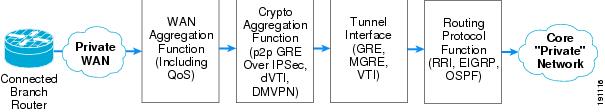
The four architectures defined for Enterprise WAN and MAN networks provide an alternative solution to private WAN technologies such as Frame Relay and ATM-based networks. The design guides written around these architectures focused on support for network growth, availability, operational expenses, voice and video support, and level of complexity. Each of the architectures can be summarized into the seven basic components shown in Figure 2.
Figure 2 Enterprise WAN and MAN High-Level Architecture Basic Components
These components are the following:
•
•
•
•
•
•
•
These seven components are the basic components needed for all the enterprise WAN and MAN architectures. Not all four architectures use every one of the seven components, but an overview of all seven is shown for completeness. Also, the WAN aggregation, crypto aggregation, tunnel interface, and routing protocol functionality components can reside in a single chassis or multiple chassis, depending on the WAN and MAN architecture chosen.
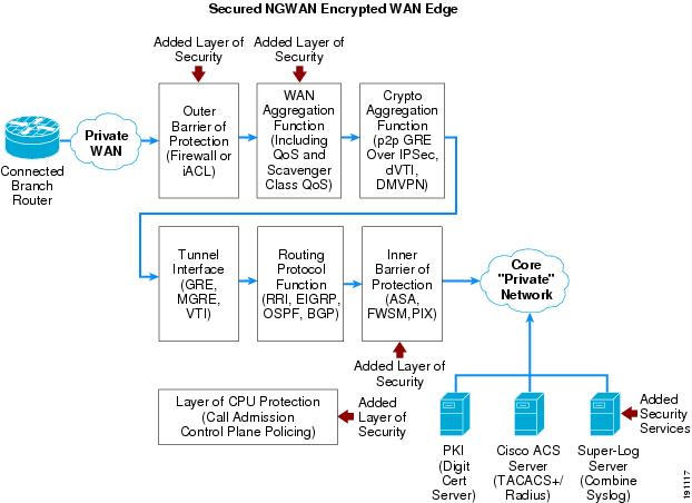
In Figure 2, no mention is made of how to secure the actual devices within the WAN edge, how to block malicious traffic from entering the WAN edge, or how to guarantee the appropriate users or branch routers are allowed into the WAN edge network. This design guide focuses on providing guidance in these areas. The component overview of the enterprise WAN and MAN architectures are supplemented with additional components to secure the WAN edge. The concept of securing the NGWAN edge is to add additional layers of security and security functions to the existing encrypted VPN topology that may exist in a WAN edge. These security features add an inner and outer layer of access control as well as basic infrastructure protections of those systems. Figure 3 shows the location of these added components.
Figure 3 Securing the WAN Edge High-Level Architecture Additional Components
These added security components are the following:
•
•
•
•
•
Each of these additional components is discussed in detail throughout this document. Figure 3 can be regarded as the high-level architecture overview to secure the enterprise WAN edge. This document takes this high-level architecture overview and creates a set of profiles for each of the two typical WAN speeds: OC3 (155 Mbps) and OC12 (622 Mbps). Two profiles are created for OC3 and two for OC12 WAN speeds. This profile approach shows each of the above components in an integrated as well as separate device network architecture based on the current platform set available from Cisco for these two WAN speeds. Each profile contains the various layers of security available in the additional components shown in Figure 3.
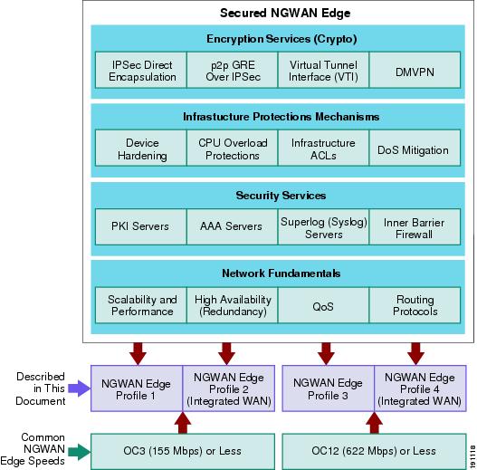
The organization of this document is summarized in Figure 4.
Figure 4 Securing the WAN Edge Documentation Framework
In addition to the additional security components, network fundamentals such as scalability and performance, high availability, QoS, and routing protocols are discussed.
WAN Speed Profiles
There are two typical WAN speeds for a WAN Edge network: OC3 (155 Mbps) and OC12 (622 Mbps). The choice of these two network speeds determines the platform set from Cisco chosen. In addition, this design guide creates two profiles for each WAN speed. These profiles are designed to provide guidance when designing a WAN edge network regardless of which enterprise WAN and MAN architecture is selected. The profiles for each WAN speed investigate integrated versus dedicated chassis for each functionality component as highlighted in the previous section. Some customers prefer a highly integrated solution where most, if not all, of the functions described in this document reside on a single or very few chassis. Other customers prefer the granularity and scalability of these same functions separated across multiple chassis. Both solutions have their advantages and disadvantages. From these profiles, guidance and configuration examples are given for securing the WAN edge mechanisms, as discussed in Figure 4. These mechanisms are encryption services (crypto), infrastructure protection services, security services, and network fundamentals.
OC3 Profiles
Based on the high-level architecture for an enterprise WAN edge network, two profiles were chosen for a WAN edge requiring an OC3 connection from the private WAN cloud. The first profile shows a dedicated chassis solution and the second profile shows an integrated solution. The platforms chosen are also discussed in the following sections.
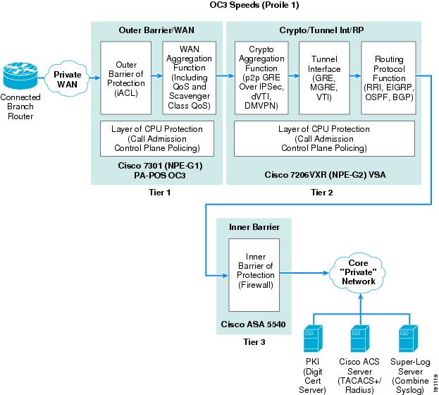
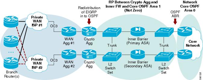
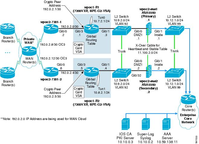
OC3 Profile 1—Three-Tier Solution
Figure 5 shows how the seven basic network components of high-level WAN edge architecture are organized to provide a dedicated chassis, separated by function solution.
Figure 5 Profile 1 OC3 Architecture (Three-Tier Solution)
To meet the OC3 WAN speed requirement, the following Cisco platforms were chosen to fulfill each network component:
•
•
•
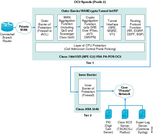
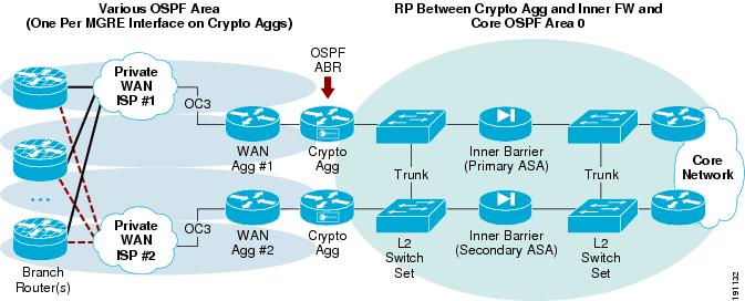
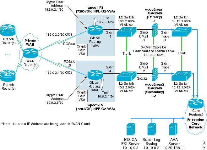
OC3 Profile 2—Two-Tier Solution
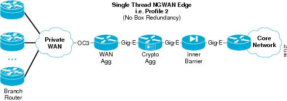
Figure 6 shows how the seven basic network components of high-level WAN edge architecture are organized to provide an integrated functionality solution.
Figure 6 Profile 2 OC3 Architecture (Two-Tier Solution)
To meet the OC3 WAN speed requirement, the following Cisco platforms were chosen to fulfill each network component:
•
•
Comparison of the OC3 Profiles
Table 1 shows the advantages and disadvantages of the two OC3 profiles created.
Both profile 1 and 2 share a dedicated inner barrier firewall of a Cisco ASA 5540 (as an inner barrier firewall).
OC12 Profiles
Based on the high-level architecture for an enterprise WAN edge network, two profiles were chosen for a WAN edge requiring an OC12 connection from the private WAN cloud. The third profile shows a dedicated chassis solution and the fourth profile shows an integrated solution at OC12 speeds. The platforms chosen are also discussed in the following sections.
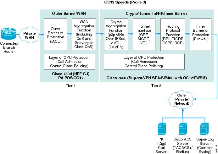
OC12 Profile 3—Two-Tier Solution
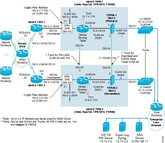
Figure 7 shows how the seven basic network components of high-level WAN edge architecture are organized to provide a dedicated chassis, two-tier solution.
Figure 7 Profile 3 OC12 Architecture (Two-Tier Solution)
To meet the OC12 WAN speed requirement, the following Cisco platforms were chosen to fulfill each network component:
•
•
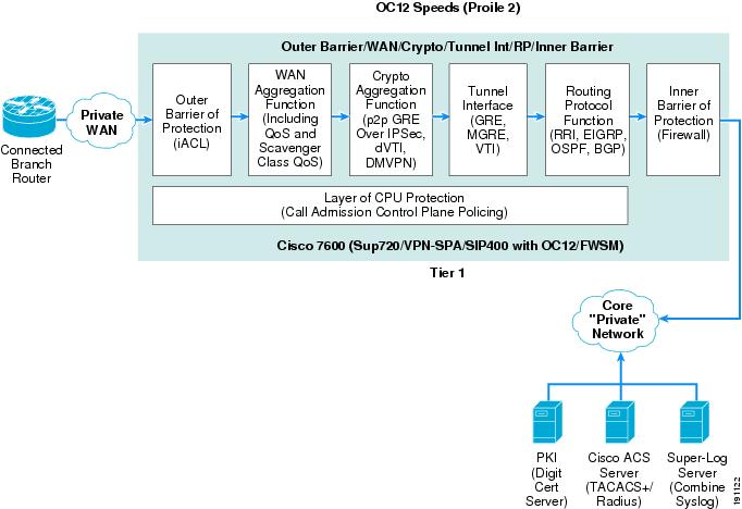
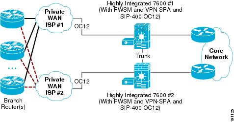
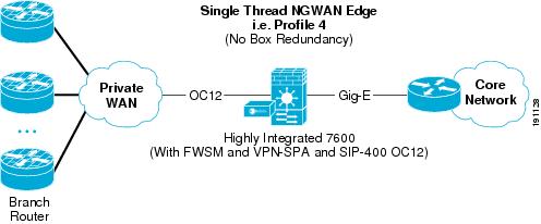
OC12 Profile 4—Integrated Functionality Solution (One-Tier Solution)
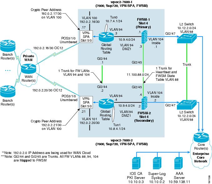
Figure 8 shows how the seven basic network components of high-level WAN edge architecture are organized to provide an integrated functionality solution.
Figure 8 Profile 4 OC12 Architecture (One-Tier Solution)
To meet the OC12 WAN speed requirement, the following Cisco platforms were chosen to fulfill each network component:
•
Comparison of the OC12 Profiles
Table 2 shows the advantages and disadvantages of the two OC12 profiles created.
Both profile 3 and 4 share a FWSM, as the inner barrier firewall. Although integrated in the 7600 chassis, the FWSM has its own independent CPU and network processors.
Securing the NG WAN Edge
The key security components of this architecture are organized in this document into three categories: infrastructure protection services, security services, and encryption services (crypto).
Encryption Services
The crypto aggregation component provides its functionality within the WAN edge. The crypto aggregation component creates a secure and encrypted communication channel between the branch sites and the core private network, as well as from "branch-to-hub-to-other branch" connections. The encryption services involve the four IPsec-based WAN architectures and are discussed in great detail in the following design guides:
•
•
•
Design and Implementation discusses these four VPN topologies as they apply to the WAN speed profiles created. Infrastructure protection services and security services are discussed in the next two sections.
Infrastructure Protection Services
Infrastructure protection services provide proactive measures to protect devices, in this case Cisco IOS software-based routers, switches, and appliances, from direct and indirect attacks. Infrastructure protection services assist in maintaining network transport continuity and availability. Regardless of which enterprise WAN and MAN architecture or WAN edge speed profile chosen, infrastructure protection services apply to all the network components in the WAN edge. To protect these devices, the following methods are used:
•
This document uses built-in facilities such as the following:
–
–
–
–
–
–
•
–
–
•
–
•
–
–
More detailed descriptions and configurations of all these infrastructure protection mechanisms are provided in Infrastructure Protection Mechanisms.
Security Services
Security services provide the added functionality within the WAN edge network to control that the appropriate users can access the network device, the appropriate certificates are given, and that a protected and archived audit trail of security events exists. The following security services methods were used:
•
•
•
•
A more detailed description and configuration of all the previous listed security services are shown in Security Service Integration.
Network Fundamentals
Network fundamentals refer to the basic services that are required for network connectivity. These services include high availability, IP routing, and QoS. Unique to the WAN edge is the scalability and performance network fundamental. Given that the WAN edge aggregates numerous branch sites and forwards that traffic to the core "private" network, selecting a platform that can meet the branch aggregation requirements and still be able to forward traffic is fundamental to a WAN edge network. Network Fundamentals discusses this network fundamental in greater detail.
High Availability
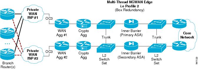
Implementing designs that incorporate high availability require the solution administrator to identify the components that may likely fail, to provide redundancy during the failure, and then to simulate a failure and recovery to test the plan. This section shows the high-level architecture of a single site, multi-threaded architecture (box-level redundancy), and discusses the architecture of a multi-site redundant architecture (geographical site redundancy). See High Availability (Redundancy) for detailed network designs and implementation information.
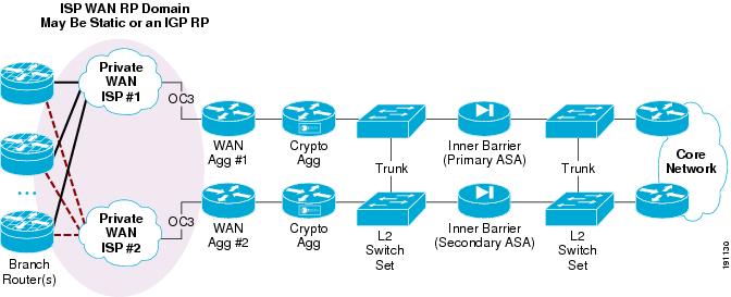
Redundant Multi-Threaded in a Single-Site Location
The core concept in this redundancy model is to supply device and circuit redundancy at each major function of the topology within a single site. The number of chasses chosen to implement the solution has a major impact on how much redundancy is possible.
Figure 9 shows an example of this multi-threaded system in a single-site location.
Figure 9 Multi-Threaded System in a Single Location (Profile 1)
There are trunk links between the core and the inner firewall, and also between the inner firewall and the crypto aggregation devices. This allows cross failover of one set of functions (that is, WAN and crypto or inner firewall) without failover of the whole thread.
Table 3 lists the advantages and disadvantages of a multi-threaded single-site deployment.
If L2 switches are required for redundancy, they may be implemented as unique sets of switches at each spot in the NGWAN edge topology. Alternatively, the L2 switches may simply be different VLANs off the same two shared switches. This choice depends on the company requirements for keeping various levels of traffic separated or not on a L2 device. Opinions on this practice vary among security professionals. If you are concerned that the L2 switches could be compromised giving access into a more protected location in the network topology, multiple independent sets of switches are recommended. See Redundant Multi-Threaded in a Single Site Location for details on topology and implementation.
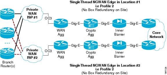
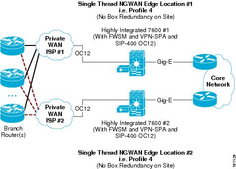
Multiple Single-Threaded Site Locations of NGWAN Edge
A single threaded solution has one path through the set of systems (a thread). By creating two or more site locations for each single thread, geographical redundancy is achieved. This NGWAN edge topology provides very good redundancy while still maintaining cost efficiency.
The example shown in Figure 10 does not provide for redundancy within a location but provides redundancy across two or more locations.
Figure 10 Multiple Single-Threaded Site Locations Redundancy (Profile 1)
In a multiple single-threaded site locations NGWAN edge redundancy model, some basic considerations need to be designed into the network for the redundancy to operate correctly. See Multiple Single-Threaded Site Locations of NGWAN Edge for details on topology and implementation.
Quality of Service
QoS (with the exception of scavenger class QoS) is implemented to achieve some guarantees on certain application performance across the network, such as VoIP traffic. For implementation details, see QoS for WAN Aggregation Routers.
Routing Protocols
Routing protocols (and possibly the redistribution of them) are extremely important to redundancy and the time to detect and respond to a failure event. This is described in detail in Routing Protocol Implementation.
For implementation details of these items, also see Network Fundamentals.
Best Practices and Known Limitations
The following sections contain a summary of the best practices and limitations for the design. More detailed information is provided in Design and Implementation.
Best Practices Summary
The following lists at a high-level the best practices recommendations for infrastructure protection and security service integration on the WAN edge systems:
•
•
•
•
•
Known Limitations Summary
The following summarizes the known limitations for infrastructure protection and security service integration on the WAN edge systems:
•
•
–
–
–
–
•
•
•
•
Additional detailed information on these recommendations is discussed in the sections that follow.
Design and Implementation
Which security products and features to include in the "securing" of the NGWAN edge, where those services should reside, and how to properly configure them, is the primary focus of this section.
Each function in this design may have network traffic that is used for itself (control plane) or for a higher level traffic. It is important to understand how the components of this architecture communicate with their counterparts at the branch location, and where each component of the NGWAN edge is meant to terminate.
The following describes the concept of different classes of traffic and the devices on which they terminate:
•
•
•
•
•
•
–
–
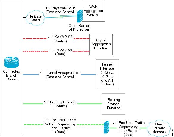
In a multi-function system such as the NGWAN edge, several types of traffic go through the system at any given time. The vast majority of the packets per second (pps) and bits per second (bps) of the traffic transiting the NGWAN edge is end-user data. A smaller proportion of the traffic is considered control plane traffic. An example of control plane traffic is the routing protocol used inside the IPsec VPN tunnel (VPN IGP) to the branches. The solution administrator may choose to use any IGP (that is, EIGRP or OSPF) as the routing protocol. This traffic is critical to the stability of the network but is not generated by the end users. It is generated and terminated by the network gear itself. Other examples of control plane traffic are ISAKMP connections for IPsec, and even the solution administrator of the system connecting to them for remote administration or device monitoring.
Figure 11 shows a comparison of control plane and data plane traffic in the NGWAN edge architecture.
Figure 11 Control Plane versus Data Plane Traffic in NGWAN Edge Architectures
Each type of connection is described in more detail as follows:
1.
2.
3.
4.
5.
a.
b.
6.
7.
Design Considerations
This section gives provides configuration summaries and more detail descriptions of the various security and other mechanisms being enabled on the NGWAN edge gear. The goal of this section is to expand on the concepts in Design Overview and provide the detail needed for the solution administrator to understand and implement each feature. This section is not a technical "deep dive" into each subject described but rather how to integrate all the various features into a comprehensive "security in layers" solution and show the difference in devices and configuration.
Most of the configuration examples in this section are based off of an "integrated WAN router" model as represented in profile 2 (OC3) or profile 4 (OC12). Full configurations for all profiles are shown in Test Bed Configuration Files.
Security Concepts—Implementation and Configuration
The key components of this infrastructure protection and security service integration are indicated by red arrows, as shown in Figure 12.
Figure 12 Implementing Security Services and Infrastructure Protections
Infrastructure Protection Mechanisms
The goals of infrastructure protection are to lessen the likelihood or amount of damage done to critical systems by a deliberate or collateral intrusion attempt or DoS-type attack on that respective system, and to prevent unauthorized access to private data or service theft of the NGWAN edge systems. The NGWAN edges are located in a campus or data center of the enterprise. The NGWAN edge solution aggregates hundreds or thousands of branch devices giving connectivity to the enterprise core network; as such, it becomes a likely target of interest to an attacker.
Device Hardening
Hardening the access options of the NGWAN edge devices and removing potentially dangerous features and services is a requirement to the securing of the NGWAN edge. A basic common sense approach to device hardening is shown in the following section.
Create a Banner
For links to both the Cisco IOS essentials (now a Cisco Press book) and the NSA document, see the following URL: http://www.thewaystation.com/techref/choke.shtml. The banner is more for establishing legal ownership and the ability to prosecute an intruder. It is similar to a "no trespassing" sign in the physical world.
Create a banner for any shell connection attempts, so that the system is clearly marked as private. Cisco recommends that you consult your legal department or group for the exact language required by your company or organization in such a banner. It is recommended not to divulge any unnecessary information in the banner (that is, device name or network administration information).
Commands for creating a banner (motd):
•
!banner motd ^CWarning this is a private system.Unauthorized access is prohibited.Violators will be prosecuted..^C!! *Note the ^C should be a character not used! in the banner itself when entered, once! enter the router will convert it to a ^C in! the configuration - this is normal.•
!banner motd Warning this is a private systembanner motd Unauthorized access is prohibited.banner motd Violators will be prosecuted.banner motd .!! *Note each line of the banner can have it's own command! in the config there is no "end of block" type character! like in IOS.Use AAA on all Devices
AAA with TACACS+ can provide an easy-to-manage source for device account administration, authorization command sets, and a repository for accounting information. These AAA commands are used in conjunction with a Cisco Secure Access Control Server (ACS) or other TACACS+ server. The following are benefits of using AAA commands with an ACS server:
•
•
•
•
•
•
Commands for Authentication, Authorization, Accounting (CLI AAA via TACACS+)
In this example, the AAA server (Cisco Secure ACS) is at 10.59.138.11 and uses a secret key between the device (NAS) and the AAA server.
•
!! Enable service password-encryption:service password-encryption!! Create a local database login! for backup if ACS is down:username cisco123 privilege 15 password 7 104D000A061843595F! Enable aaa new-model mode for AAAaaa new-model!! Configuring location of the TACACS+ Server and parameters:tacacs-server host 10.59.138.11 key 7 070C285F4D06!tacacs-server timeout 10tacacs-server directed-request!! AAA Authentication commands: (request authentication via! tacacs+ for both login and for enable level:aaa authentication login default group tacacs+ local enableaaa authentication enable default group tacacs+ enable! AAA authorization (with command set send down from tacacs+):aaa accounting exec default start-stop group tacacs+!! AAA accounting to TACACS+ for start-stop records (for! session time and also any commands entered in privilege! level 0, 1, and 15 :aaa accounting exec default start-stop group tacacs+aaa accounting commands 0 default start-stop group tacacs+aaa accounting commands 1 default start-stop group tacacs+aaa accounting commands 15 default start-stop group tacacs+aaa session-id common!! *Note - In the aaa accounting commands you need to create on! for each privilege level you wish to go to accounting.! This behavior configures differently then in ASA/FWSM code.•
!! Create a local database login! for backup if ACS is down:username cisco123 password ffIRPGpDSOJh9YLq encrypted privilege 15! Configuring location of the TACACS+ Server and parameters:aaa-server tacacs-group protocol tacacs+aaa-server tacacs-group host 10.59.138.11key ciscoaaa-server TACACS+ protocol tacacs+!! AAA Authentication commands: (request authentication via! tacacs+ for both login and for enable level:aaa authentication enable console tacacs-group LOCALaaa authentication ssh console tacacs-group LOCALaaa authentication telnet console tacacs-group LOCAL! if you are on an ASA Security Appliance you will need this additional command! which is not necessary on a FWSM:aaa authentication serial console tacacs-group LOCAL!! AAA authorization (with command set PIX SHELL send down from tacacs+):aaa authorization command tacacs-group LOCAL! AAA accounting to TACACS+ for start-stop records (for session time! in either telnet or ssh and also any commands entered for privilege! level 1 thru 15aaa accounting telnet console tacacs-groupaaa accounting ssh console tacacs-groupaaa accounting command tacacs-group!! *Note - the "aaa accounting command" is for that level and up! this example was 1 and up - which is default! This behavior is configures differently then in Cisco IOSAAA configuration and behavior is slightly different in Cisco IOS, Cisco ASA 5540, and Cisco FWSM. In general, the use of AAA is the same on all platforms: to provide a userID/password login for "privilege level 1", and to enable password login for "enable or configure" (privilege level 15) commands.
In Cisco IOS devices, the configuration of this document uses the "default" group. This uses a userID/password for the "privilege level 1" login, and depending on the account setup in the AAA (Cisco Secure ACS) server, may also require a separate "enable" level login (privilege level 15). This is true whether the solution administrator connects via SSH or via the physical console port. Both use the default of AAA. As a backup if the AAA server is unavailable, there is a "local account" configured in the device, but this is used only if the AAA server is unreachable from that specific device.
In a Cisco ASA security appliance, the commands are slightly different, there is no default, and the solution administrator must configure the AAA authentication command per communication protocol in which the AAA is to be applied. The commands differ in syntax from traditional IOS AAA commands; the term console really means command-line interface (CLI). The physical port of the console is actually named serial in the configuration, and AAA must be applied to this separately. If a solution administrator connects to the Cisco ASA via SSH or via the serial (physical console) port, AAA behavior is determined by that specific command in the configuration. The default behavior, if no AAA policy is applied to the serial, is to use the login "enable_1" for the account ID, although this is not recommended. Only the active ASA in a failover pair has the OSPF routing table that gives a dynamic network route to the AAA server if more that one hop away; thus, only the active system has access to the AAA server, super-log syslog server, and so on. Any static routes are valid on the "standby" but not any dynamically learned routes via a dynamic routing protocol (that is, OSPF in this document). This means that a serial (physical console) connection on the standby unit must use the local user account in the configuration to get either "privilege level 1 or 15" access via the physical console port.
In a Cisco FWSM, the commands are mostly similar to the Cisco ASA Security Appliance, but there is no physical serial console on the module. The solution administrator can connect via SSH or by connecting via a special command issued on the 7600 chassis where the module is installed. That command is session slot 4 processor 1, where the FWSM is installed in slot 4 of the chassis. This creates a reverse telnet from the 7600 chassis to the FWSM for administration. The FWSM always accepts this reverse telnet from the 7600, even when the Telnet protocol has been disabled and the AAA rules apply. Much like on the ASA appliances, only the active has routes via a dynamic routing protocol, so if the AAA server is more than one hop away (and no static route exists to it), you need to use the login of the local account in the configuration on the standby unit.
Restrict Shell Access to SSH instead of Telnet
Use SSH instead of Telnet for remote administration of devices in the NGWAN edge. This provides an encryption shell and adds encrypted privacy to the administrative shell session of the solution administrator to prevent snooping by unwanted parties.
When an solution administrator uses Telnet or r-shell (rsh) to access a device, the UserID and password for that shell session are sent over the network in clear text, as well as any commands they may enter or the responses to those commands. By allowing only SSH, the shell session of the solution administrator is encrypted and uses keyed endpoint authentication to keep the session private and not easily viewable. The solution administrator needs to carefully choose Cisco IOS images for their routers that support SSH (usually indicated in the image description or as a 3DES image).
Commands for only using SSH (no telnet or other protocols) for an administrative shell are as follows:
•
!! set the routers hostname and domainhostname wpoc1-r1ip domain name ese.cisco.com!! Create a key for SSH:cry key generate rsa general-keys modulus 1024!! set at SSH version 2 and parametersip ssh time-out 30ip ssh source-interface gi0/1ip ssh authentication-retries 3ip ssh logging events! ***SSH logging not available in cisco 7600 image tested.ip ssh version 2!! This allow ONLY ssh (not telnet) as an inbound! management shellline vty 0 15transport input ssh...!•
!! set the firewall's hostname and domainhostname wpoc2-asa1domain-name ese.cisco.com!! Create a key for SSH:cry key generate rsa modulus 1024!! *Note - see section below to set range of valid client IP's! before it will operate - This is required.Using ACLs to Restrict Access
An important step in hardening the devices is to use access control of any protocols that are permitted to the devices for administrative or monitoring purposes (that is, SNMP, SSH, and other protocols used to monitor the devices). A basic shell setting such as a timeout value (not infinite) is also strongly recommended.
In the ASA/FWSM, take special care when allowing SNMP on the inner barrier firewall. Cisco strongly recommends that if you wish to poll the ASA/FWSM, use the configuration similar to what is shown in the configurations below. This allows polling from a particular host, but does not configure an SNMP trap to be sent to that host. A busy firewall such as the ASA or FWSM located in the NGWAN edge with a high level of syslogging (that is, syslog level 6 or 7) can output a tremendous amount of syslog/SNMP traps, so it can easily overwhelm a normal network management system with SNMP traps. Cisco does not recommend using SNMP trap for the firewall to a network management system. If you choose to do this, trap only lower level events.
The SNMP shown in the example below is SNMPv3, and is using the authentication and encryption options of v3. Some network management stations may require a lower version of SNMP or may not support the authentication option shown here. The solution administrator should contact the network management team and see what SNMP support level is possible in the network NMS tools before implementation. For example, Cisco Works (CW), Cisco LNS, Cisco Resource Manager Essentials (RME) for the most part do not support authpriv, but do support most other common NMS systems (such as HP OpenView).
SNMPv3 is an interoperable standards-based protocol defined in RFCs 2273 to 2275. SNMPv3 provides secure access to devices by a combination of authenticating and encrypting packets over the network.
The security features provided in SNMPv3 are as follows:
•
•
•
•
Note
The following are commands for access control of device administration protocols (access control of SSH is in the following section):
•
!! Define a standard ACL of which subnets or hosts are ALLOW! access to VTY and/or SNMP!access-list 10 permit 10.0.0.0 0.255.255.255access-list 10 deny any log!!! Applies ACL 10 to control access to the VTY ports and also! set the timeout for a shell to 3 minutesline vty 0 4access-class 10 inexec-timeout 3 0...!! if you allow or wish to use SNMP to these devices you should! at a minimum tie the ACL for access control for Reading! and possible encrypt, authentication, and hash communication if supported by! the NMS station (SNMPv3)!snmp-server group NMS v3 privsnmp-server user nmsstation NMS v3 auth md5 remoteNMS priv 3des NMSpassword access 10! *** Note the line entered above will not show in running config,! do a "show snmp user" to confirm!•
!! Access control for SSH for ASA:! Enter a line for each subnets you wish to allow SSH accessssh 10.0.0.0 255.0.0.0 dmz1ssh 10.0.0.0 255.0.0.0 insidessh scopy enable!! This set the timeout period for an existing SSH shell to 3 minutesssh timeout 3!! Repeat line below for any existing telnet permitted subnets.no telnet <network> <mask> <interface>telnet timeout 1!! Also set a console timeout:console timeout 3!! if SNMP is used to poll Firewall then set the host(s) allowed to poll:! repeat for any stations that will be permitted to pollsnmp-server host inside 10.10.0.4 poll community NMScommunity version 2csnmp-server location inner-barriersnmp-server contact admin@company.comsnmp-server community NMScommunity! Disable trappingno snmp-server enable traps snmp authentication linkup linkdown coldstartno snmp-server enable traps all!For more information on SNMPv3, its parameters and other options, see the following URL: http://www.cisco.com/en/US/docs/ios/12_2/configfun/configuration/guide/fcf014.html.
Disable all Known Hazardous or Unused Features
Disable all known potentially hazardous and unused features, such as directed broadcasts, IP redirect, IP proxy-ARP, CDP, small services, and the built-in global HTTP/HTTPS daemons in Cisco IOS.
The ASA and FWSM have a secure web-based graphical user interface (GUI) for administration of the system named Adaptive Security Device Manager (ASDM). Enabling this GUI requires that the ASA/FWSM run an extra image (separate from the image the chassis runs) on that system in the flash disk. For proper operation, the image for the ASDM GUI and the image that runs on the chassis need to be downloaded and installed together in lock step. The following configurations show how to enable and access-control which IP addresses can access that GUI. The use of this GUI is completely optional, and can be downloaded from the following URL: http://www.cisco.com/en/US/products/ps6121/index.html.
Most Cisco IOS routers also have a secure web-based GUI interface for administration named Secure Device Manager (SDM). It is shown as disabled in the configurations below, which is done by disabling the HTTP and HTTPS daemons.
Cisco recommends that on all Cisco IOS systems, enable secret be used instead of enable password, and also enabling service password-encryption to hash other passwords in the configuration when possible.
Following are commands for the disabling of known hazardous or unneeded features:
•
!! Enable Service password encryptionservice password-encryption!! Disable CDP globally and other un-required features! *Note - some of these are already off by default! and just being shown for completeness:no cdp runno service udp-small-serversno service tcp-small-servers!! The SDM GUI uses the web server(s) in the IOS router! by disabling them the SDM GUI is disabled.no ip httpno ip https!! On ALL active Layer 3 interfaces (up-up) - turn off default interface behaviors that can be misused. You do not need to do this on L2 interface (like a port that is a "switchport mode":interface <xxxxx>no ip proxy-arpno ip redirectno ip directed-broadcastno cdp enable!•
!! These features are not enabled on a ASA/FWSM - no action required!! *** if you wish to use ASA User Auth (Uauth) or the ASA! Secure Device Manager (ASDM) you will need to enable! the http services like the following:http server enablehttp 10.0.0.0 255.0.0.0 dmz1http 10.0.0.0 255.0.0.0 inside!Restrict Dynamic Routing Protocols
By default, routing updates on either a Cisco IOS router or Cisco ASA/FWSM are sent unauthenticated and un-hashed (sent in clear text). A malicious attacker who knows the routing protocol process number can become a routing peer and then send or receive routing information with the routing devices. This can lead to false routes being injected into the NGWAN edge routing information and may lead to network disruption or enabling an intruder to gain more access to the network than the solution administrator intended.
To overcome this, for all routing protocols used (this document uses EIGRP and OSPF), configure a key and enable the hashing option in that dynamic routing protocol.
The following commands are used for authentication and hashing of the routing protocol (OSPF). EIGRP is used in this document inside the mGRE tunnels (VPN IGP) from the branch routers to the NGWAN crypto aggregation system. It is then redistributed into OSPF from the crypto aggregation routers to the inner barrier (firewall) and into the private core network.
•
!! Create an ACL for the what is permitted to be redistributedip access-list extended route-redist-ACLpermit ip 10.2.0.0 0.0.255.255 any!! Create a route-map for the redistributed! This example prefers Crypto Agg 1 over crypto Agg 2! for all connected branches. You may wish a split of active! branches (see appropriate VPN design guide for details).route-map route-redist permit 10match ip address route-redist-ACLmatch metric 15388160set metric 30!route-map route-redist permit 20match ip address route-redist-ACLmatch metric 12828160set metric 20!! Securing (Authenticating RP - OSPF)router ospf 100router-id 10.9.2.3log-adjacency-changes! area 1 statement below sets that MD5 hashing is required! in area OSPF area 1:area 1 authentication message-digestredistribute eigrp 1 subnets route-map route-redistpassive-interface POS5/0passive-interface Tunnel1network 10.2.0.0 0.0.255.255 area 1network 10.7.2.0 0.0.0.255 area 1network 10.8.2.0 0.0.0.255 area 1network 10.9.2.0 0.0.0.255 area 1network 10.10.0.0 0.0.255.255 area 1network 10.12.1.0 0.0.0.255 area 1!! on neighboring interfaces set that authentication and MD5! hashing are required:interface GigabitEthernet0/1description to-ASA...ip ospf authentication message-digestip ospf authentication-key 7 00071A150754...!•
! Securing (Authenticating RP - OSPF)!router ospf 100network 10.0.0.0 255.0.0.0 area 1! area 1 statement below sets that MD5 hashing is required! in area OSPF area 1:area 1 authentication message-digestrouter-id 10.9.2.1log-adj-changes!!! on neighboring interfaces set that authentication and MD5! hashing are required:interface GigabitEthernet0/0description DMZ1nameif dmz1security-level 50...ospf authentication-key ciscoospf authentication message-digest!! on neighboring interfaces set that authentication and MD5! hashing are required:interface GigabitEthernet0/1description insidenameif insidesecurity-level 100ip address 10.12.1.1 255.255.255.0 standby 10.12.1.2ospf authentication-key ciscoospf authentication message-digest!The following commands are used for authentication and hashing of the routing protocol (EIGRP).
Note
•
!! Create a key-chain for use by EIGRP for authenticationkey chain 1key 1key-string cisco!! This is the basic eigrp configuration! use the passive-interface on any interface that you do! not wish to listen for RP updates.router eigrp 1passive-interface FastEthernet0/0passive-interface GigabitEthernet0/1passive-interface POS5/0network 10.0.0.0no auto-summary!! Require the key and md5 hashing of EIGRP messages! this would also be done on tun1 on appropriate systeminterface tun0ip authentication mode eigrp 1 md5ip authentication key-chain eigrp 1 1...ip summary-address eigrp 1 10.0.0.0 255.0.0.0 5ip summary-address eigrp 1 0.0.0.0 0.0.0.0 6...no ip split-horizon eigrp 1ip hold-time eigrp 1 35...!•
!! Create a key-chain for use by EIGRP for authenticationkey chain 1key 1key-string cisco!! This is the basic eigrp configuration! use the passive-interface on any interface that you do! not wish to listen for RP updates.router eigrp 1network 10.0.0.0no auto-summary!! Require the key and md5 hashing of EIGRP messagesinterface tun0ip authentication mode eigrp 1 md5ip authentication key-chain eigrp 1 1...!! Require the key and md5 hashing of EIGRP messagesinterface tun1ip authentication mode eigrp 1 md5ip authentication key-chain eigrp 1 1...!Outer Barrier—Infrastructure ACLs (iACLs) and Logging
An infrastructure ACL (iACL) is used as the outer barrier (the first line of defense) from the WAN interface connected to the service provider (SP) cloud. The primary function of the iACL is to allow the cipher traffic (encrypted VPN tunnel traffic) from the branch router and possibly some other basic services (such as NTP or a routing protocol to the SP if desired), and deny all non-permitted traffic with some logging of packets that are denied. This iACL is used primarily to attempt to stop unauthorized access, DoS attacks, or DDoS attacks that originate from the SP or a network connected to the SP, as well as preventing intrusions and data/service theft. This network location usually cannot inspect the end user data packets because they are already encapsulated and encrypted at this location in the solution, so making decisions based on those end user packets/flows is also not possible. Most of the advanced firewalling options are also not possible in the network location of this device. A solution administrator could alternately use a full "stateful inspection firewall" (such as a Cisco FWSM or Cisco ASA) in this network location, but it would not be very well used in this spot in the network and most dedicated firewall products do not support WAN type interfaces directly at this time.
The logging of denied attempts is a critical function for the security audit trail. The solution administrator needs to have a reasonable amount of logs entries to do the following:
•
•
•
The question arises as to whether to log denied attempts. The answer is to definitely log but within the limits of the system. Use the logging options but with special features and rate limiting in place and tuned to the respective system so as to not overwhelm the host CPU on that system. It is also a common security practice to log to the internal buffer log of the device for troubleshooting and real-time viewing, while concurrently logging off-system to a protected dedicated remote syslog server (this is also known as super-logging or remote syslogging).
The iACL behaves and logs slightly differently on the Cisco 7200VXR and Cisco 7300 Series routers and on the Cisco 7600 Series routers, as described in the following subsections.
iACL and Logging on the Cisco 7200VXR Platform
On the Cisco 7200VXR platform, the switching path of the device, whether a separate dedicated WAN router or as an integrated part of the crypto aggregation system, the "log" statements in the access list can cause the system to go to process switch mode for the logging of an access list line hit. A prolonged high CPU utilization can cause the network to become unstable and unavailable. To mitigate this problem, it is strongly recommended that you use the available logging and rate limiting commands available in Cisco IOS to help contain the amount of logging per second the device with the iACL does.
The following is a configuration for iACL and logging on the Cisco 7200VXR platform. This example is from Profile 2 (crypto and WAN interface on a Cisco 7200VXR). This sets up some logging options, creates an iACL, and applies it to an outside (POS) interface:
!!! Set logging host and levelservice timestamps debug datetime localtime show-timezoneservice timestamps log datetime localtime show-timezone!! Set logging host and levellogging buffered 32768 informationallogging 10.10.0.2! *Note the command below is ONLY use with a Cisco 7200 VXR or 7301 or 7304! systems and is not required with a Cisco 7600 with OAL enabled.logging rate-limit 1 except notifications!ip access-list extended InfraProtremark -------------------------------------------------------remark usual anti-frag rulesdeny tcp any any log fragmentsdeny udp any any log fragmentsdeny icmp any any log fragmentsremark -------------------------------------------------------remark usual anti-spoofing rulesdeny ip host 0.0.0.0 any logdeny ip 127.0.0.0 0.255.255.255 any logremark Usually the subnet 192.0.2.0/24 is not internet routable andremark is usually blocked - but in this document we are using part 192.0.2.0/25remark as the subnet for the addressing of the WAN cloud IP addressing so partremark of it will be omitted from the deny below.deny ip 192.0.2.128 0.0.0.127 any logdeny ip 224.0.0.0 31.255.255.255 any logdeny ip host 255.255.255.255 any logdeny ip 10.0.0.0 0.255.255.255 any logdeny ip 172.16.0.0 0.15.255.255 any logdeny ip 192.168.0.0 0.0.255.255 any logremark -------------------------------------------------------remark permit GRE and isakmp/esp and inbound icmp echo to outside-intpermit gre any host 192.0.2.1permit udp any host 192.0.2.1 eq isakmppermit udp any host 192.0.2.1 eq non500-isakmppermit esp any host 192.0.2.1permit icmp any host 192.0.2.1 echopermit icmp any host 192.0.2.1 packet-too-bigpermit icmp any host 192.0.2.1 unreachablepermit icmp any host 192.0.2.1 time-exceededremark -------------------------------------------------------remark default deny all log..deny ip any any log!interface POS5/0description OC3-to-wan-rtrip address 192.0.2.1 255.255.255.252ip access-group InfraProt in...!iACL and Logging on the Cisco 7304 and the 7301 Platforms
On the Cisco 7304 or Cisco 7301 platforms, the switching path of the device, whether on a separate dedicated WAN router or on a chassis that also runs crypto, the log statements in the access list can cause the system to go to process switch mode for the logging of an access list line hit. A prolonged high CPU utilization can cause the network to become unstable and unavailable. To mitigate this problem, it is strongly recommended that you use the available logging and rate limiting commands available in Cisco IOS to help contain the amount of logging per second done by the device with the iACL.
Following is a configuration example for iACL and logging on the Cisco 7304 or Cisco 7301 platform. This sets up some logging options, creates an iACL, and applies it to an outside (POS) interface:
!! Set logging host and levelservice timestamps debug datetime localtime show-timezoneservice timestamps log datetime localtime show-timezone!! Set logging host and levellogging buffered 32768 informationallogging 192.0.2.17!! *Note the command below is ONLY use with a Cisco 7200 VXR or 7301 or 7304! systems and is not required with a Cisco 7600 with OAL enabled.logging rate-limit 1 except notifications!ip access-list extended InfraProtremark -------------------------------------------------------remark usual anti-frag rulesdeny tcp any any log fragmentsdeny udp any any log fragmentsdeny icmp any any log fragmentsremark -------------------------------------------------------remark usual anti-spoofing rulesdeny ip host 0.0.0.0 any logdeny ip 127.0.0.0 0.255.255.255 any logremark Usually the subnet 192.0.2.0/24 is not internet routable andremark is usually blocked - but in this document we are using part 192.0.2.0/25remark as the subnet for the addressing of the WAN cloud IP addressing so partremark of it will be omitted from the deny below.deny ip 192.0.2.128 0.0.0.127 any logdeny ip 224.0.0.0 31.255.255.255 any logdeny ip host 255.255.255.255 any logdeny ip 10.0.0.0 0.255.255.255 any logdeny ip 172.16.0.0 0.15.255.255 any logdeny ip 192.168.0.0 0.0.255.255 any logremark -------------------------------------------------------remark permit GRE and isakmp/esp and inbound icmp echo to outside-intremark This line is not required on WAN rtr - permit gre any host 192.0.2.17permit udp any host 192.0.2.17 eq isakmppermit udp any host 192.0.2.17 eq 4500permit esp any host 192.0.2.17permit icmp any host 192.0.2.17 echopermit icmp any host 192.0.2.17 packet-too-bigpermit icmp any host 192.0.2.17 unreachablepermit icmp any host 192.0.2.17 time-exceededremark -------------------------------------------------------remark default deny all log..deny ip any any log!!interface POS5/0/0description OC12-TO-WAN-RTRip address 192.0.2.25 255.255.255.252ip access-group InfraProt inno ip redirectsno ip proxy-arpload-interval 30clock source internalno cdp enable!iACL and Logging on the Cisco 7600 Platform
The Cisco 7600 platform (with a Sup720 [PFC3]) has a special feature called Optimized Access List (OAL) that is not available in the other Cisco router series. OAL should be used to optimize the logging function and to offload the processing of the iACL and the respective logging to the PFC3 card. This allows this platform to perform a much more detailed level of logging of denies while still preserving the CPU rate of the MSFC (used for other critical functions such as dynamic routing, IKE, ISAKMP, and so on).
For more details on the OAL feature in the Cisco 7600 Series, see Understanding Cisco IOS ACL Support at the following URL: http://www.cisco.com/en/US/docs/routers/7600/ios/12.2SXF/configuration/guide/acl.html.
Note
The line in the iACL that permits ESP protocol never has any counters in a show access-list InfraProt command. This is because the VPN-SPA gets the ESP traffic "bridged down" to the hardware accelerator before the ACL can be incremented. The PFC3 on the Supervisor720 (Sup720) encapsulates or decapsulates the mGRE in hardware (because of unique source and no tunnel-key), but the line for that in the iACL is not incremented. This is considered normal behavior and does not affect operations. These iACL lines are still shown in the iACL for completeness and parity to the other profiles.
Following is the configuration for iACL and OAL logging on the Cisco 7600 platform. This sets up some logging options, creates an iACL, and applies it to an outside (vlan100) interface.
!!! Set logging host and levelservice timestamps debug datetime localtime show-timezoneservice timestamps log datetime localtime show-timezone!! Set logging host and levellogging buffered 32768 informationallogging 10.10.0.2!!ip access-list extended InfraProtremark -------------------------------------------------------remark usual anti-frag rulesdeny tcp any any log fragmentsdeny udp any any log fragmentsdeny icmp any any log fragmentsremark -------------------------------------------------------remark usual anti-spoofing rulesdeny ip host 0.0.0.0 any logdeny ip 127.0.0.0 0.255.255.255 any logremark Usually the subnet 192.0.2.0/24 is not internet routable andremark is usually blocked - but in this document we are using part 192.0.2.0/25remark as the subnet for the addressing of the WAN cloud IP addressing so partremark of it will be omitted from the deny below.deny ip 192.0.2.128 0.0.0.127 any logdeny ip 224.0.0.0 31.255.255.255 any logdeny ip host 255.255.255.255 any logdeny ip 10.0.0.0 0.255.255.255 any logdeny ip 172.16.0.0 0.15.255.255 any logdeny ip 192.168.0.0 0.0.255.255 any logremark -------------------------------------------------------remark permit GRE and isakmp/esp and inbound icmp echo to outside-intpermit gre any host 192.0.2.17permit udp any host 192.0.2.17 eq isakmppermit udp any host 192.0.2.17 eq non500-isakmppermit esp any host 192.0.2.17permit icmp any host 192.0.2.17 echopermit icmp any host 192.0.2.17 packet-too-bigpermit icmp any host 192.0.2.17 unreachablepermit icmp any host 192.0.2.17 time-exceededremark -------------------------------------------------------remark default deny all log..deny ip any any log!! Apply it inbound on the other L3 interface.!interface Vlan100description VLAN OUTside VPNSPA targetip address 192.0.2.17 255.255.255.252ip access-group InfraProt inip verify unicast source reachable-via rx allow-defaultno ip redirectsno ip proxy-arp! It is strongly recommend to enable the Optimized Access List (OAL) feature on the PFC3 card for the! Cisco 7600 platform. You enable it on the interface doing the logging as such:logging ip access-list cache inload-interval 30no mop enabledcrypto map dynamic-mapcrypto engine subslot 5/0!Control Plane Policing
At the highest level, Control Plane Policing (CoPP) uses QoS traffic policers to restrict the amount of traffic that is destined to the system on which it is configured. The goal of this feature is to keep a high-level of requests or packets of valid permitted traffic from causing the CPU of the system to spike up and become unstable. Often DoS and DDoS attacks make use of a high volume of normal traffic in an attempt to run a system out of resources and become unavailable.
A basic example of this is if the solution administrator has SSH enabled on the device for device administration, and an attacker sends a flurry of SSH requests in an attempt to eat up CPU and cause the device to be so busy so it does not respond to a critical task (such as routing hellos), and makes the network unstable.
More information on CoPP is available at the following URL: http://www.cisco.com/en/US/docs/ios/12_3t/12_3t4/feature/guide/gtrtlimt.html.
CoPP must be "tuned" to the chassis on which it runs and checked periodically for changes in traffic by the solution administrator. The speed of the router processor, the type of traffic that is permitted and rate limited in the policy map, and the switching path in which it occurs (that is, process, CEF, FAST, and so on) can all have an impact on how efficiently CoPP operates on that particular platform. Although this tuning may be difficult, the value of CoPP to prevent an abnormal amount of authorized traffic is a powerful infrastructure protection and worth the investment of time to configure and tune.
The following configuration of CoPP on Cisco 7200VXR (NPE-G2) is an example of some basic CPU and traffic rate policing to this chassis. This example is from Profile 2.
!ip access-list extended coppacl-bgpremark BGP traffic classpermit tcp 192.0.2.0 0.0.0.128 host 192.0.2.5 eq bgppermit tcp 192.0.2.0 0.0.0.128 eq bgp host 192.0.2.5!ip access-list extended coppacl-critical-appremark CoPP critical apps traffic classpermit ip any host 224.0.0.2!ip access-list extended coppacl-filemanagementremark CoPP File transfer traffic classpermit tcp any eq ftp any gt 1023 establishedpermit tcp any eq ftp-data any gt 1023permit tcp any gt 1023 any gt 1023 establishedpermit udp any gt 1023 any gt 1023!ip access-list extended coppacl-igpremark IGP traffic classpermit ospf 10.9.2.0 0.0.0.255 host 224.0.0.5permit ospf 10.9.2.0 0.0.0.255 host 224.0.0.6permit ospf 10.9.2.0 0.0.0.255 host 10.9.2.4permit ospf 10.8.2.0 0.0.0.255 host 10.8.2.1permit eigrp 10.0.0.0 0.255.255.255 host 224.0.0.10permit eigrp 10.0.0.0 0.255.255.255 host 10.8.2.1!ip access-list extended coppacl-managementremark CoPP management traffic classpermit tcp any eq tacacs any establishedpermit tcp any any eq 22permit tcp any any eq telnetpermit udp any any eq snmppermit udp any any eq ntp!ip access-list extended coppacl-monitoringremark CoPP monitoring traffic classpermit icmp any any ttl-exceededpermit icmp any any port-unreachablepermit icmp any any echo-replypermit icmp any any echo!ip access-list extended coppacl-vpnpermit gre any host 192.0.2.5permit udp any host 192.0.2.5 eq isakmppermit udp any host 192.0.2.5 eq non500-isakmppermit esp any host 192.0.2.5!class-map match-all coppclass-critical-appmatch access-group name coppacl-critical-appclass-map match-all coppclass-vpnmatch access-group name coppacl-vpnclass-map match-all coppclass-igpmatch access-group name coppacl-igpclass-map match-all coppclass-bgpmatch access-group name coppacl-bgpclass-map match-all coppclass-monitoringmatch access-group name coppacl-monitoringclass-map match-all coppclass-filemanagementmatch access-group name coppacl-filemanagementclass-map match-all coppclass-managementmatch access-group name coppacl-management!policy-map copp-policyclass coppclass-igpclass coppclass-filemanagementclass coppclass-bgppolice cir 80000 bc 8000 be 8000conform-action transmitexceed-action dropclass coppclass-managementpolice cir 10000000 bc 100000 be 100000conform-action transmitexceed-action dropclass coppclass-monitoringpolice cir 500000 bc 5000 be 5000conform-action transmitexceed-action dropclass coppclass-critical-apppolice cir 500000 bc 5000 be 5000conform-action transmitexceed-action dropclass coppclass-vpnclass class-defaultpolice cir 10000000 bc 100000 be 100000conform-action transmitexceed-action drop!!control-planeservice-policy input copp-policy!The following configuration of CoPP on the Cisco 7600 is an example of some basic CPU and traffic rate policing to this chassis. This example is from Profile 4.
!ip access-list extended coppacl-bgpremark BGP traffic classpermit tcp 192.0.2.0 0.0.0.128 host 192.0.2.17 eq bgppermit tcp 192.0.2.0 0.0.0.128 eq bgp host 192.0.2.17!ip access-list extended coppacl-critical-appremark CoPP critical apps traffic classpermit ip any host 224.0.0.2!ip access-list extended coppacl-filemanagementremark CoPP File transfer traffic classpermit tcp any eq ftp any gt 1023 establishedpermit tcp any eq ftp-data any gt 1023permit tcp any gt 1023 any gt 1023 establishedpermit udp any gt 1023 any gt 1023!ip access-list extended coppacl-igpremark IGP traffic classpermit ospf 10.9.4.0 0.0.0.255 host 224.0.0.5permit ospf 10.9.4.0 0.0.0.255 host 224.0.0.6permit ospf 10.9.4.0 0.0.0.255 host 10.9.4.3permit ospf 10.7.4.0 0.0.0.255 host 10.7.4.1permit eigrp 10.0.0.0 0.255.255.255 host 10.7.4.1permit eigrp 10.0.0.0 0.255.255.255 host 224.0.0.10!ip access-list extended coppacl-managementremark CoPP management traffic classpermit tcp any eq tacacs any establishedpermit tcp any any eq 22permit tcp any any eq telnetpermit udp any any eq snmppermit udp any any eq ntp!ip access-list extended coppacl-monitoringremark CoPP monitoring traffic classpermit icmp any any ttl-exceededpermit icmp any any port-unreachablepermit icmp any any echo-replypermit icmp any any echo!ip access-list extended coppacl-vpnpermit gre any host 192.0.2.17permit udp any host 192.0.2.17 eq isakmppermit udp any host 192.0.2.17 eq non500-isakmppermit esp any host 192.0.2.17!!class-map match-all coppclass-critical-appmatch access-group name coppacl-critical-appclass-map match-all coppclass-vpnmatch access-group name coppacl-vpnclass-map match-all coppclass-igpmatch access-group name coppacl-igpclass-map match-all coppclass-bgpmatch access-group name coppacl-bgpclass-map match-all coppclass-monitoringmatch access-group name coppacl-monitoringclass-map match-all coppclass-filemanagementmatch access-group name coppacl-filemanagementclass-map match-all coppclass-managementmatch access-group name coppacl-management!policy-map copp-policyclass coppclass-bgppolice cir 4000000 bc 400000 be 400000 conform-action transmit exceed-action dropclass coppclass-igppolice cir 300000 bc 3000 be 3000 conform-action transmit exceed-action dropclass coppclass-filemanagementpolice cir 6000000 bc 60000 be 60000 conform-action transmit exceed-action dropclass coppclass-managementpolice cir 500000 bc 5000 be 5000 conform-action transmit exceed-action dropclass coppclass-monitoringpolice cir 900000 bc 9000 be 9000 conform-action transmit exceed-action dropclass coppclass-critical-apppolice cir 900000 bc 9000 be 9000 conform-action transmit exceed-action dropclass coppclass-vpnpolice cir 6000000 bc 60000 be 60000 conform-action transmit exceed-action dropclass class-defaultpolice cir 500000 bc 5000 be 5000 conform-action transmit exceed-action drop!!control-plane!service-policy input copp-policy!!The following configuration of CoPP on Cisco 7301 WAN router is an example of some basic CPU and traffic rate policing to this chassis. This is an example from Profile 1.
Note
!!ip access-list extended coppacl-bgpremark BGP traffic class - this class for BGP to ISP if desired.permit tcp 192.0.2.0 0.0.0.128 host 192.0.2.9 eq bgppermit tcp 192.0.2.0 0.0.0.128 eq bgp host 192.0.2.9!ip access-list extended coppacl-critical-appremark CoPP critical apps traffic classpermit ip any host 224.0.0.2!ip access-list extended coppacl-filemanagementremark CoPP File transfer traffic classpermit tcp any eq ftp any gt 1023 establishedpermit tcp any eq ftp-data any gt 1023permit tcp any gt 1023 any gt 1023 establishedpermit udp any gt 1023 any gt 1023!ip access-list extended coppacl-managementremark CoPP management traffic classpermit tcp any eq tacacs any establishedpermit tcp any any eq 22permit tcp any any eq telnetpermit udp any any eq snmppermit udp any any eq ntp!ip access-list extended coppacl-monitoringremark CoPP monitoring traffic classpermit icmp any any ttl-exceededpermit icmp any any port-unreachablepermit icmp any any echo-replypermit icmp any any echo!class-map match-all coppclass-critical-appmatch access-group name coppacl-critical-appclass-map match-all coppclass-bgpmatch access-group name coppacl-bgpclass-map match-all coppclass-monitoringmatch access-group name coppacl-monitoringclass-map match-all coppclass-filemanagementmatch access-group name coppacl-filemanagementclass-map match-all coppclass-managementmatch access-group name coppacl-management!policy-map copp-policydescription NOTE that the IGP and VPN classes are removed on WAN rtr CoPP configclass coppclass-filemanagementclass coppclass-bgppolice cir 80000 bc 8000 be 8000conform-action transmitexceed-action dropclass coppclass-managementpolice cir 10000000 bc 100000 be 100000conform-action transmitexceed-action dropclass coppclass-monitoringpolice cir 500000 bc 5000 be 5000conform-action transmitexceed-action dropclass coppclass-critical-apppolice cir 500000 bc 5000 be 5000conform-action transmitexceed-action dropclass class-defaultpolice cir 10000000 bc 100000 be 100000conform-action transmitexceed-action drop!!control-planeservice-policy input copp-policy!!The following configuration of CoPP on Cisco 7304 WAN router is an example of some basic CPU and traffic rate policing to this chassis. This example is from Profile 3.
Note
!!ip access-list extended coppacl-bgpremark BGP traffic class - this class for BGP to ISP if desired.permit tcp 192.0.2.0 0.0.0.127 host 192.0.2.25 eq bgppermit tcp 192.0.2.0 0.0.0.127 eq bgp host 192.0.2.25!ip access-list extended coppacl-critical-appremark CoPP critical apps traffic classpermit ip any host 224.0.0.2!ip access-list extended coppacl-filemanagementremark CoPP File transfer traffic classpermit tcp any eq ftp any gt 1023 establishedpermit tcp any eq ftp-data any gt 1023permit tcp any gt 1023 any gt 1023 establishedpermit udp any gt 1023 any gt 1023!ip access-list extended coppacl-managementremark CoPP management traffic classpermit tcp any eq tacacs any establishedpermit tcp any any eq 22permit tcp any any eq telnetpermit udp any any eq snmppermit udp any any eq ntp!ip access-list extended coppacl-monitoringremark CoPP monitoring traffic classpermit icmp any any ttl-exceededpermit icmp any any port-unreachablepermit icmp any any echo-replypermit icmp any any echo!class-map match-all coppclass-critical-appmatch access-group name coppacl-critical-appclass-map match-all coppclass-bgpmatch access-group name coppacl-bgpclass-map match-all coppclass-monitoringmatch access-group name coppacl-monitoringclass-map match-all coppclass-filemanagementmatch access-group name coppacl-filemanagementclass-map match-all coppclass-managementmatch access-group name coppacl-management!policy-map copp-policydescription NOTE that the IGP and VPN classes are removed on WAN rtr CoPP configclass coppclass-filemanagementclass coppclass-bgppolice cir 80000 bc 8000 be 8000conform-action transmitexceed-action dropclass coppclass-managementpolice cir 10000000 bc 100000 be 100000conform-action transmitexceed-action dropclass coppclass-monitoringpolice cir 500000 bc 5000 be 5000conform-action transmitexceed-action dropclass coppclass-critical-apppolice cir 500000 bc 5000 be 5000conform-action transmitexceed-action dropclass class-defaultpolice cir 10000000 bc 100000 be 100000conform-action transmitexceed-action drop!control-planeservice-policy input copp-policy!Further documentation of the CoPP feature on Cisco IOS-based routers is at the following URL: http://www.cisco.com/en/US/docs/ios/12_3t/12_3t4/feature/guide/gtrtlimt.html.
Call Admission Control (CAC) for IKE
This feature helps keep the number of concurrent IKE requests from overwhelming the CPU of the NGWAN crypto aggregation system. This is likely to occur in the event of the system recovering after a box failure (that is, boot or reboot). All the branches (which may be in the thousands) attempt to connect to the crypto aggregation system at once, which can result in a race condition that makes the network stabilization take longer than desired. To help restrict the speed at which "new" IPsec peers and routing peers are established, this feature prefers the current connections over new connections. This keeps the IPsec and routing peers that have been established up while slowly adding more each time slice. Without this feature enabled, you may find a situation where three IPsec and routing peers are established, and then two go down while the next few are being processed. This results in IPsec and routing flapping that causes high CPU and network instability. Fortunately, the call-admission limit % command corrects this situation.
CAC polls a global resource monitor, so that IKE knows when the router is running short of CPU cycles or memory buffers. You can configure a resource limit, from 1 to 100, that represents a percentage of system resources. When that level of CPU utilization is reached, the IKE process drops the SA requests (and does not accept new requests). Cisco recommends a value such as 70 percent of CPU.
The configuration of CAC on Cisco IOS platforms is as follows:
!call admission limit 70!Further documentation of the CAC for IKE feature is available at the following URL: http://www.cisco.com/en/US/docs/ios/security/configuration/guide/sec_call_addmsn_ike_ps6350_TSD_Products_Configuration_Guide_Chapter.html.
Note
Unicast Reverse Path Forwarding
As a basic measure to protect against spoofing-based attacks, the Unicast Reverse Path Forwarding (uRPF) check should be performed. The uRPF feature discards packets that lack a consistent source IP address, such as spoofed IP source addresses created by malicious users to intercept valuable data. This feature uses Cisco Express Forwarding (CEF) tables to verify that the source addresses and the interfaces on which packets were received are consistent with the forwarding tables on the supervisor engine. If the packet is received from reverse path routes, the packet is forwarded. If there is no reverse path route on the interface on which the packet was received, the packet fails the uRPF check and is discarded silently.
uRPF can be deployed throughout the campus network at hardware-based performance rates.
An optional ACL can be tied into the ip verify command (ip verify unicast reverse-path <list>) to provide a finer grain control over what is discarded if desired.
Note
The following configuration of uRPF on Cisco IOS and firewall platforms is an example of using uRPF check in the CEF table for packets arriving on the interface to see whether a reverse path route exists to that interface for that source IP of a received packet.
•
! On a Cisco 7200VXR or Cisco 7301 or Cisco 7304:! This following command placed on the WAN interface! toward the SP cloudinterface POS5/0...ip verify unicast reverse-path...!! on a Cisco 7600 platform! This following command placed on the VLAN interface! that is crypto connected to the WAN interface! toward the SP cloudinterface VLAN100...ip verify unicast source reachable-via rx allow-default...!•
!! This following command placed on the outside interface! toward the crypto Agg and wan router (global command)ip verify reverse-path interface dmz1!Further documentation of uRPF features is available at the following URLs:
•
•
•
Aside from being an efficient anti-spoofing solution, uRPF can also be used effectively in combination with static routes pointing to Null0 adjacencies to drop traffic from specific hosts or networks. Null0 Forwarding Information Base (FIB) adjacencies can in turn be distributed automatically with internal BGP (iBGP) to quickly drop packets from infected hosts (also known as remotely triggered blackhole filtering). This is not described in this document, but more information on remotely triggered blackhole filtering is available at the following URL: http://www.cisco.com/warp/public/732/Tech/security/docs/blackhole.pdf
Scavenger Class QoS
The Scavenger Class QoS strategy is to identify known worms and attacks and drop those packets at a point very close to the end user (usually the switch port at which they are connected). Other traffic patterns from that end user that are considered "unusual" or is "normal traffic but at an unusually high rate" may be marked as scavenger class-CS1 in the DSCP field and allow to pass through the switch. If a device in the branch, NGWAN edge, or campus has a choke point where congestion occurs, the first thing the QoS policy drops is this "anomalous traffic" that is marked CS1.
Because no end user devices are directly plugged into the NGWAN edge gear, it shapes into a very small amount of bandwidth any traffic that the campus or branch switches have marked this way, but these systems do not mark the traffic themselves.
Further documentation of the Scavenger Class QoS feature is at the following URL: http://www.cisco.com/en/US/docs/solutions/Enterprise/WAN_and_MAN/QoS_SRND/QoS-SRND-Book.html.
The configuration of a scavenger class is part of the bigger QoS policy that is applied to the WAN circuit. See the following configuration for an example of this class as part of a V3PN-style QoS policy map (CBWFQ-LLQ).
The following configuration of Scavenger Class QoS on a Cisco VXR Platform is an example of creating a general V3PN QoS map and adds in the Scavenger Class QoS class.
!!class-map match-any VOICEmatch ip dscp efmatch ip precedence 5class-map match-all SCAVENGERmatch ip dscp cs1class-map match-any CALL-SETUPmatch ip dscp af31match ip dscp cs3match ip precedence 3class-map match-any INTERNETWORK-CONTROLmatch ip dscp cs6match ip precedence 6class-map match-any TRANSACTIONAL-DATAmatch ip dscp af21match ip precedence 2!!policy-map OC-WAN-wSCAVENGERclass CALL-SETUPbandwidth percent 5class INTERNETWORK-CONTROLbandwidth percent 5class VOICEpriority percent 33class TRANSACTIONAL-DATAbandwidth percent 30class SCAVENGERbandwidth percent 1class class-defaultbandwidth percent 25random-detect!!interface POS5/0description OC3-to-wan-rtr...max-reserved-bandwidth 100service-policy output OC-WAN-wSCAVENGER!The following configuration of Scavenger Class QoS on a Cisco 7600 platform is an example of a general V3PN QoS map and adds in the Scavenger Class QoS class.
!! Because of the use of SIP-400 card carrier and a SPA POS OC-12 card some minor! configuration difference are require to achieve the same affect:!class-map match-any VOICEmatch ip dscp efmatch ip precedence 5class-map match-all SCAVENGERmatch ip dscp cs1class-map match-any CALL-SETUPmatch ip dscp af31match ip dscp cs3match ip precedence 3class-map match-any INTERNETWORK-CONTROLmatch ip dscp cs6match ip precedence 6class-map match-any TRANSACTIONAL-DATAmatch ip dscp af21match ip precedence 2!! The difference between the OC12 QoS map here and the OC3 one on the VXR is that the ! VOICE class can NOT use! a priority percent or priority bandwidth statement on a SIP-400. So therefore a policer ! in the strict priority queue must be used.!policy-map OC12-WAN-wSCAVENGERdescription VOICE-class is 33% of OC-12(622M) aka 205,000,000class VOICEprioritypolice cir 205000000 bc 2050000 be 2050000 conform-action transmit exceed-action dropclass INTERNETWORK-CONTROLbandwidth percent 5class CALL-SETUPbandwidth percent 5class TRANSACTIONAL-DATAbandwidth percent 30class SCAVENGERbandwidth percent 1class class-defaultbandwidth percent 25random-detect!!interface POS3/1/0description OC12-TO-WAN-RTR...crypto connect vlan 100service-policy output OC12-WAN-wSCAVENGER!Security Service Integration
Inner Barrier—Stateful Inspection Firewall
The inner barrier, usually a fully functional stateful inspection firewall product (Cisco FWSM or a Cisco ASA system) is tasked with access control of the end user traffic that is from branch to campus or campus to branch. This location can use the basic features in a typical Cisco firewall such as NAT functionally, access control, and application inspection. The solution administrator may also use more advanced firewall techniques such as URL filtering, user authentication, and others. The location in the topology of this device can inspect end user traffic that is in clear text (not encrypted) and allows for more fine grain checks and controls on that traffic. The primary function of the inner barrier firewall is traffic (access) control, but also supplies some DoS protection from attacks originating from within the tunnel either to or from a connected branch.
A stateful inspection firewall is used as the inner barrier (the last line of defense) that can inspect the branch clear text traffic (traffic that has already been decrypted) that is destined to the campus network or Internet.
Because this firewall is able to inspect the end user traffic, this firewall can perform access control from branches to the campus core or to the Internet, as well as more advanced firewall features such as user authentication, URL filtering/logging, and so on. The inner barrier firewall may also be used as the Internet gateway edge device in a given location. This fits well if the branch routers do not do "split tunneling". Split tunneling is where a branch router sends traffic that is destined to the Internet directly to the Internet and not through the VPN tunnel. If the branch routers are not doing split tunneling, all traffic goes to the crypto aggregation device. Traffic destined to either the campus or Internet then goes to the inner firewall. Branch-to-branch encrypted traffic (even in a hub-and-spoke topology) goes to the crypto aggregation system but not to the firewall. This is a limitation of the solution.
This document uses either Cisco ASA Firewall or the Cisco FWSM with a basic firewall rule set and no NAT translations of subnets that are in the enterprise core (inside) to the branch side (DMZ1).
The following is a configuration of ASA 5540 with active primary ASA and partial configuration of interfaces, NAT, rule set and inspections:
! Interfaces:!interface GigabitEthernet0/0description DMZ1nameif dmz1security-level 50ip address 10.9.2.1 255.255.255.0 standby 10.9.2.2ospf authentication-key ciscoospf authentication message-digest!interface GigabitEthernet0/1description insidenameif insidesecurity-level 100ip address 10.12.1.1 255.255.255.0 standby 10.12.1.2ospf authentication-key ciscoospf authentication message-digest!! Nat Rules: to keep internal networks on the same IP subnets (not NATing)nat-controlstatic (inside,dmz1) 10.10.0.0 10.10.0.0 netmask 255.255.0.0static (inside,dmz1) 10.12.1.0 10.12.1.0 netmask 255.255.255.0static (inside,dmz1) 10.59.138.0 10.59.138.0 netmask 255.255.254.0! Rule base:access-list inside_access_in extended permit icmp any anyaccess-list inside_access_in extended permit ip any any!access-list dmz1_access_in extended permit icmp any any logaccess-list dmz1_access_in extended permit ip 10.2.0.0 255.255.0.0 10.0.0.0 255.0.0.0access-list dmz1_access_in extended permit ip 10.9.2.0 255.255.255.0 10.0.0.0 255.0.0.0access-list dmz1_access_in extended permit ip 10.8.2.0 255.255.255.0 10.0.0.0 255.0.0.0access-list dmz1_access_in extended permit ip 10.7.2.0 255.255.255.0 10.0.0.0 255.0.0.0access-list dmz1_access_in extended deny ip any any logaccess-group dmz1_access_in in interface dmz1access-group inside_access_in in interface inside!! Dynamic inspections:!class-map inspection_defaultmatch default-inspection-traffic!!policy-map global_policyclass inspection_defaultinspect ftpinspect h323 h225inspect h323 rasinspect rshinspect skinnyinspect esmtpinspect sqlnetinspect sipinspect dns maximum-length 512inspect netbiosinspect sunrpcinspect tftpinspect xdmcp!service-policy global_policy global!The following is a configuration of the FWSM, with active primary FWSM (and partial configuration of interfaces, NAT, rule set and inspections) and also the 7600 commands to trunk down VLANs to FWSM:
! COMMANDS on 7600 to trunk vlan down to FWSMfirewall module 4 vlan-group 1firewall vlan-group 1 88,94,104! ON FWSM:! Interfaces:!interface Vlan94nameif dmz1security-level 50ip address 10.9.4.1 255.255.255.0 standby 10.9.4.2ospf authentication-key ciscoospf authentication message-digest!interface Vlan104nameif insidesecurity-level 100ip address 10.12.2.1 255.255.255.0 standby 10.12.2.2ospf authentication-key ciscoospf authentication message-digest!! Nat Rules: to keep internal networks on the same IP subnets (not NATing)nat-controlstatic (inside,dmz1) 10.10.0.0 10.10.0.0 netmask 255.255.0.0static (inside,dmz1) 10.12.2.0 10.12.2.0 netmask 255.255.255.0static (inside,dmz1) 10.59.138.0 10.59.138.0 netmask 255.255.254.0! Rule base:access-list inside_access_in extended permit icmp any anyaccess-list inside_access_in extended permit ip any any!access-list dmz1_access_in extended permit icmp any any logaccess-list dmz1_access_in extended permit ip 10.4.0.0 255.255.0.0 10.0.0.0 255.0.0.0access-list dmz1_access_in extended permit ip 10.9.4.0 255.255.255.0 10.0.0.0 255.0.0.0access-list dmz1_access_in extended permit ip 10.8.4.0 255.255.255.0 10.0.0.0 255.0.0.0access-list dmz1_access_in extended permit ip 10.7.4.0 255.255.255.0 10.0.0.0 255.0.0.0access-list dmz1_access_in extended deny ip any any logaccess-list inside_access_in extended permit icmp any anyaccess-list inside_access_in extended permit ip any any!! Dynamic inspections:!class-map inspection_defaultmatch default-inspection-traffic!policy-map global_policyclass inspection_defaultinspect dns maximum-length 512inspect ftpinspect h323 h225inspect h323 rasinspect netbiosinspect rshinspect skinnyinspect smtpinspect sqlnetinspect sunrpcinspect tftpinspect sipinspect xdmcp!service-policy global_policy globalSuper-Logging (Remote SYSLOG Server)
The goal of this mechanism is to provide one unified syslog of all the systems that compose the NGWAN edge (whether Cisco IOS routers, ASA/FSWM, or other devices capable of syslog output) and optionally even the branch routers. A "super-log" is very useful in a multi-system architecture because all the NGWAN edge devices syslog to a single super-log server. The super-log should be backed up regularly, as a recording keeping mechanism of all relevant devices. As the solution administrator, you need to have some records of what, when, and how often an incident occurred to engage the authorities in the event of an attack or intrusion. You may also be required to collect these logs for prosecutors, legal, or governmental entities. The type of operating system and syslog product on the super-log syslog server is a matter of the preference of the solution administrator: various UNIXs, Windows-based (with syslog application), or others are all potential choices. It is not as important as the availability and ability to do some basic log file rotation and archiving.
The Cisco Monitoring Analysis Reporting System (MARS) is also a possible candidate to be the super-log. Cisco MARS can do event correlation to reduce the amount of labor involved in log review, and bring intelligence to the logs as well as alarming and even NetFlow options.
Note
A super-log that is stored in the protected network using files, rather than a wrapping buffer, is a good security mechanism by itself. It is a common practice of attackers to attempt an intrusion and then to initiate many DoS attacks to fill the logging buffer of network gear to wrap the intrusion attempt out of the buffer log. A well-configured and secure super-log is off the attacked system and is not susceptible to this type of attack.
Note
A best effort (usually UDP-based) syslog super-log of all devices is recommended in most profiles and does not become a point of failure in the security architecture (as TCP-guaranteed logging may cause). In a security appliance (such as PIX, ASA, or FWSM), the solution manager must take care to log only to the syslog level that is required. A firewall set at a high-level of logging can generate a tremendous amount of logging information (this is also true of SNMP traps). In the following example, the ASA/FWSM is logged at "syslog level 6 (informational) into the internal buffer" but only at "syslog level 5 (notifications)" to the super-log. This represents a customer who does not require URL or connection level logging that occurs at syslog level 6. This is not a one size fits all parameter, and the enterprise needs to see what level is enough for it. There are also rate limiting options in the firewall appliances, but if a correct level is chosen, the need to rate limit it is greatly reduced.
The following commands are for configuring the remote syslog to a super-log server. This assumes that each device has NTP configured and running.
•
! Set network time protocol (NTP) to sync to a clockclock timezone est -5clock summer-time edt recurringntp server 10.10.0.1 source GigabitEthernet0/1!! Set logging host and levelservice timestamps debug datetime localtime show-timezoneservice timestamps log datetime localtime show-timezone!! Set logging host and levellogging buffered 32768 informationallogging 10.10.0.2! *Note the command below is ONLY use with a Cisco 7200 VXR! system and is not require with a Cisco 7600 with OAL! enabled.logging rate-limit 1 except notifications!•
Note
! Set network time protocol (NTP) to sync to a clockclock timezone est -5clock summer-time edt recurringntp server 10.10.0.1 source inside prefer!! Set logging host and levellogging enablelogging timestamplogging standbylogging buffered informationallogging trap notifications!! The following line is only required if the ASDM GUI is enabled.logging asdm informationallogging host inside 10.10.0.2!AAA Server Integration—Access Control Server (via TACACS+)
A TACACS+ server was implemented for control of AAA from the network devices in the NGWAN edge topology. This document describes a Cisco Secure ACS server (v3.3) located in the private (protected) network to be a repository for administration accounts (UserID/Password) and also to provide downloadable command sets to both the Cisco IOS and ASA/FWSM systems, and lastly to provide an accounting server for record of all logins and commands issued on the respective network gear.
For more information on the configuration of a Cisco Secure ACS server, see the Cisco Secure ACS documentation at the following URL: http://www.cisco.com/en/US/products/sw/secursw/ps2086/index.html.
PKI Digital Certificates
This document describes a Cisco IOS Certificate Authority (CA) server running a Cisco IOS router that is located in the private (protected) core network and issues certificates to the NGWAN edge crypto aggregation devices as well as the branches that connects to them. There are some security and scalability benefits of using X.509 certificates rather than the other options for IKE authentication (wildcard pre-shared keys, per-peer pre-shared keys, or IKE aggressive mode). Digital Certificates offer a highly secure but still very scalable and manageable solution for IKE authentication.
The Certificate Authority issues a certificate to each device and signs it with the public signing certificate of the CA. That device certificate is valid only on that system that contains the private key and only for the time determined when it was issued. The CA has facilities such as a Certificated Revocation List (CRL) for revoking a particular certificate without affecting the other certificates that it has issued.
Table 4 shows a comparison of PKI Digital Certificates with other IKE authentication methods.
The next section provides the configuration of both crypto VPN and digital certificates on the crypto aggregation systems.
Implementation and basic management of a PKI infrastructure is described in Digital Certificates/PKI for IPsec VPNs at the following URL: http://www.cisco.com/en/US/docs/solutions/Enterprise/Security/DCertPKI.html
Encryption Services (VPN Topology)
The choice of which VPN topology is used is the largest and most important decision in this process. It has major ramifications to the configuration, routing protocol, performance, and scalability. The VPN topologies have been already described in detail in their respective design guides.
The crypto aggregation function usually includes the actual crypto aggregation as well as tunnel interfaces and the VPN IGP routing protocol (used "in" the VPN tunnel). This may be on a single chassis or have multiple chasses for scalability.
The high-level aspects of each of the NGWAN VPN design topologies are listed in Table 5.
For an overview, see the IPsec VPN Design Overview at the following URL: http://www.cisco.com/en/US/docs/solutions/Enterprise/WAN_and_MAN/IPSec_Over.html.
This helps you choose which VPN solution is right for your deployment.
See also the following NGWAN VPN topology design guides:
•
•
•
It is important that the solution administrator choose Cisco IOS images for the crypto aggregation systems that support the encryption level (3DES or AES) that they desire to use, and it is always recommended to use a hardware crypto accelerator.
This document uses a DMVPN (dual hub-dual cloud) hub-and-spoke as the basis for documentation purposes, although any of the various VPN topologies listed above can also be a viable choice. The use of PKI X.509 Digital Certificates was also used as a strong and scalable authentication for IKE on the crypto IPsec VPN tunnels. See PKI Digital Certificates for details on implementing digital certificates.
The following are commands for configuration of DMVPN on Cisco 7200VXR crypto aggregation systems. This document uses a DMVPN hub-and-spoke topology (dual hub-dual cloud) as the crypto topology from the crypto aggregation system to the branch routers.
•
!ip host wpoc3-r1 10.10.0.3!crypto pki trustpoint ese-ios-caenrollment url http://wpoc3-r1:80revocation-check crlauto-enroll 70!!crypto pki certificate chain ese-ios-cacertificate 053082026B 308201D4 A0030201 02020105 300D0609 2A864886 F70D0101 040500307F311C30 1A06092A 864886F7 0D010901 160D2065 73652D76 706E2D74 65616D310C300A06 03550408 1303204E 43311130 0F060355 04071308 2052616C 65696768311B3019 06035504 0A131220 43697363 6F205379 7374656D 7320496E 63310D300B060355 040B1304 20455345 31123010 06035504 03130920 77706F63 332D7231301E170D 30363036 30393135 34313537 5A170D30 38303630 38313534 3135375A30273125 30230609 2A864886 F70D0109 02161677 706F6331 2D72312E 6573652E63697363 6F2E636F 6D30819F 300D0609 2A864886 F70D0101 01050003 818D003081890281 8100E983 7A05FE61 6456E526 45F91462 98B5B452 56B01B19 380DB530693116DE AFA693CF 6101413B 5FB3A141 3F2E18CA 9FCCBA8E 6DE638C6 61BF524C288FAC70 E96495CF 70C4B6FE 6D04C49E 88246645 F0C05552 079FEAD0 2A00E932D1AB056A E377E441 DC66998F 15F6EAA5 EF7F7F59 3BA4F53A 97BBA338 F5F8EC3FA4B1CD6A 30D70203 010001A3 4F304D30 0B060355 1D0F0404 030205A0 301F0603551D2304 18301680 1433F99C A898E52D 26D2B97C A26D05FC 1EF109C3 45301D0603551D0E 04160414 5998F583 47BEC171 BB297786 1BA75A95 5EBE5135 300D06092A864886 F70D0101 04050003 818100D1 5D87FF1F D3C5FD0B 3B39FAF2 D1DBDB3C75651151 CF9AABAE 1B45E8B4 CBC104B6 62AD6489 42267761 25F0D039 70107A3BF60F5F36 5A79FBF6 4BC0DBB5 7073EB93 9553C6EE EBB04A6D 4148DDA6 C08D26687964997E 6815DB9A CD4AB633 E567F861 83ACC246 283114B6 B00FE406 884984A10EF96354 2162AD9C E7AAB15C 840EE7quitcertificate ca 01308202D7 30820240 A0030201 02020101 300D0609 2A864886 F70D0101 040500307F311C30 1A06092A 864886F7 0D010901 160D2065 73652D76 706E2D74 65616D310C300A06 03550408 1303204E 43311130 0F060355 04071308 2052616C 65696768311B3019 06035504 0A131220 43697363 6F205379 7374656D 7320496E 63310D300B060355 040B1304 20455345 31123010 06035504 03130920 77706F63 332D7231301E170D 30363033 31343231 33323136 5A170D31 30303331 33323133 3231365A307F311C 301A0609 2A864886 F70D0109 01160D20 6573652D 76706E2D 7465616D310C300A 06035504 08130320 4E433111 300F0603 55040713 08205261 6C65696768311B30 19060355 040A1312 20436973 636F2053 79737465 6D732049 6E63310D300B0603 55040B13 04204553 45311230 10060355 04031309 2077706F 63332D723130819F 300D0609 2A864886 F70D0101 01050003 818D0030 81890281 8100EB326078EF84 40A19FB3 05775BA2 E7BFFE87 17AF2FEE 3E5C9387 0D9FAB35 A418607345CA8B41 DE7C1FB4 B99D0093 69AD253C E7829575 6956D485 B78B18E2 A10D9EC404CEE4A5 9AFEF3FB E10E9A61 2A224B7E 50D6E7DA 3B7501E7 D49E8F73 9DD90CFC89050020 BBFB63C1 82A092D0 C36D322C 46AD2132 11D5E531 0E55C0E9 66E70203010001A3 63306130 0F060355 1D130101 FF040530 030101FF 300E0603 551D0F0101FF0404 03020186 301F0603 551D2304 18301680 1433F99C A898E52D 26D2B97CA26D05FC 1EF109C3 45301D06 03551D0E 04160414 33F99CA8 98E52D26 D2B97CA26D05FC1E F109C345 300D0609 2A864886 F70D0101 04050003 81810080 FC245598CA42E74B 960901C7 E1E11205 5EDBF3D8 38767D96 C4307F85 0C905FCF 0BC687C0C88302D0 32EBBACA 6124BEAE 43C6A984 0E1D733B F404A684 793E1526 C25637A199A3E97B C92C5E41 DAB0DCDD 324631B087266EC9 21FEC360 13FC20C3 9B18CFE475F7A788 E0855654 49880300 95BB46D7 F37A63F0 FFB7855F FCD3F6quit!!! In the crypto isakmp policy RSA mode is the default! (PKI Digital Certificates is the default)crypto isakmp policy 10encr 3desgroup 2!! Configure a DPD keepalive - ALWAYS...crypto isakmp keepalive 10!!crypto ipsec transform-set vpn-test esp-3des esp-sha-hmac!crypto ipsec profile vpn-dmvpnset transform-set vpn-test!interface Tunnel0description Tunnel0bandwidth 1000000ip address 10.7.2.1 255.255.255.0no ip redirectsno ip proxy-arpip hold-time eigrp 1 35ip authentication mode eigrp 1 md5ip authentication key-chain eigrp 1 1ip nhrp authentication testip nhrp map multicast dynamicip nhrp network-id 105600ip nhrp holdtime 300no ip split-horizon eigrp 1ip summary-address eigrp 1 10.0.0.0 255.0.0.0 5ip summary-address eigrp 1 0.0.0.0 0.0.0.0 250qos pre-classifytunnel source POS5/0tunnel mode gre multipointtunnel key 105600tunnel protection ipsec profile vpn-dmvpn!!! Used in this document as static route to branches, could also! use a routing protocol over the wan or with the wan ISP(i.e. bgp)ip route 192.0.2.0 255.255.255.128 192.0.2.2!•
!ip host wpoc3-r1 10.10.0.3!crypto pki trustpoint ese-ios-caenrollment url http://wpoc3-r1:80revocation-check nonesource interface FastEthernet0/0auto-enroll 70!!crypto pki certificate chain ese-ios-cacertificate 0930820227 30820190 A0030201 02020109 300D0609 2A864886 F70D0101 040500307F311C30 1A06092A 864886F7 0D010901 160D2065 73652D76 706E2D74 65616D310C300A06 03550408 1303204E 43311130 0F060355 04071308 2052616C 65696768311B3019 06035504 0A131220 43697363 6F205379 7374656D 7320496E 63310D300B060355 040B1304 20455345 31123010 06035504 03130920 77706F63 332D7231301E170D 30363036 30393135 35303332 5A170D30 38303630 38313535 3033325A30273125 30230609 2A864886 F70D0109 02161677 706F6331 2D72382E 6573652E63697363 6F2E636F 6D305C30 0D06092A 864886F7 0D010101 0500034B 003048024100BEC6 4CC7E6E0 9FAFDEC6 F91C6D67 82FF943C 3ABD1CEB 675E6A94 222A2D5628522A22 8DDC598C 81110895 A5956402 F6A38C93 B8B94957 8870A341 FEC0F64554F30203 010001A3 4F304D30 0B060355 1D0F0404 030205A0 301F0603 551D230418301680 1433F99C A898E52D 26D2B97C A26D05FC 1EF109C3 45301D06 03551D0E04160414 7977C6FA E05E3352 D25A374D 8C22F369 7DE93ADF 300D0609 2A864886F70D0101 04050003 8181006A 96338109 7B07667E D7AF2148 60FEA48E 2DE5BFBBCCD48148 BB157A44 D3035BFE D2AD5F93 B710F490 42B196F4 B27BB9FC A2586708690A60C4 4C33F207 ACBF5622 93EB4821 5D4F2C73 BDDDAE63 E36641F8 A46963B31051D25F 813E1A67 25523974 7E425EA1 BA28AEE0 0CF2F32E 2C0F7DAE 3D40CCD0C986668D F7518168 2AD904quitcertificate ca 01308202D7 30820240 A0030201 02020101 300D0609 2A864886 F70D0101 040500307F311C30 1A06092A 864886F7 0D010901 160D2065 73652D76 706E2D74 65616D310C300A06 03550408 1303204E 43311130 0F060355 04071308 2052616C 65696768311B3019 06035504 0A131220 43697363 6F205379 7374656D 7320496E 63310D300B060355 040B1304 20455345 31123010 06035504 03130920 77706F63 332D7231301E170D 30363033 31343231 33323136 5A170D31 30303331 33323133 3231365A307F311C 301A0609 2A864886 F70D0109 01160D20 6573652D 76706E2D 7465616D310C300A 06035504 08130320 4E433111 300F0603 55040713 08205261 6C65696768311B30 19060355 040A1312 20436973 636F2053 79737465 6D732049 6E63310D300B0603 55040B13 04204553 45311230 10060355 04031309 2077706F 63332D723130819F 300D0609 2A864886 F70D0101 01050003 818D0030 81890281 8100EB326078EF84 40A19FB3 05775BA2 E7BFFE87 17AF2FEE 3E5C9387 0D9FAB35 A418607345CA8B41 DE7C1FB4 B99D0093 69AD253C E7829575 6956D485 B78B18E2 A10D9EC404CEE4A5 9AFEF3FB E10E9A61 2A224B7E 50D6E7DA 3B7501E7 D49E8F73 9DD90CFC89050020 BBFB63C1 82A092D0 C36D322C 46AD2132 11D5E531 0E55C0E9 66E70203010001A3 63306130 0F060355 1D130101 FF040530 030101FF 300E0603 551D0F0101FF0404 03020186 301F0603 551D2304 18301680 1433F99C A898E52D 26D2B97CA26D05FC 1EF109C3 45301D06 03551D0E 04160414 33F99CA8 98E52D26 D2B97CA26D05FC1E F109C345 300D0609 2A864886 F70D0101 04050003 81810080 FC245598CA42E74B 960901C7 E1E11205 5EDBF3D8 38767D96 C4307F85 0C905FCF 0BC687C0C88302D0 32EBBACA 6124BEAE 43C6A984 0E1D733B F404A684 793E1526 C25637A199A3E97B C92C5E41 DAB0DCDD 324631B0 87266EC9 21FEC360 13FC20C3 9B18CFE475F7A788 E0855654 49880300 95BB46D7 F37A63F0 FFB7855F FCD3F6quit!!! In the crypto isakmp policy RSA mode is the default! (PKI Digital Certificates is the default)crypto isakmp policy 10encr 3desgroup 2!! Configure a DPD keepalive - ALWAYS...crypto isakmp keepalive 10!!crypto ipsec transform-set vpn-test esp-3des esp-sha-hmac!crypto ipsec profile vpn-dmvpnset transform-set vpn-test!!interface Tunnel0description Tunnel0 - to wpoc1-r1bandwidth 1000000ip address 10.7.2.10 255.255.255.0ip hold-time eigrp 1 35ip authentication mode eigrp 1 md5ip authentication key-chain eigrp 1 1ip nhrp authentication testip nhrp map multicast 192.0.2.1ip nhrp map 10.7.2.1 192.0.2.1ip nhrp network-id 105600ip nhrp holdtime 300ip nhrp nhs 10.7.2.1qos pre-classifytunnel source FastEthernet0/1tunnel destination 192.0.2.1tunnel key 105600tunnel protection ipsec profile vpn-dmvpn!interface Tunnel1description Tunnel1 - to wpoc1-r2 - secondary by routingbandwidth 1000000ip address 10.8.2.10 255.255.255.0ip hold-time eigrp 1 35ip authentication mode eigrp 1 md5ip authentication key-chain eigrp 1 1ip nhrp authentication testip nhrp map multicast 192.0.2.5ip nhrp map 10.8.2.1 192.0.2.5ip nhrp network-id 105640ip nhrp holdtime 300ip nhrp nhs 10.8.2.1delay 60000qos pre-classifytunnel source FastEthernet0/1tunnel destination 192.0.2.5tunnel key 105601tunnel protection ipsec profile vpn-dmvpn!! To prevent recursive routing.ip route 192.0.2.0 255.255.255.128 192.0.2.33!The following are commands for the configuration of DMVPN Cisco 7600 crypto aggregation systems. This document uses a DMVPN hub-and-spoke topology (dual hub-dual cloud) as the crypto topology from the crypto aggregation system to the branch routers. This example does not use mGRE tunnel keys.
•
!ip host wpoc3-r1 10.10.0.3!crypto pki trustpoint ese-ios-caenrollment url http://wpoc3-r1:80revocation-check crlauto-enroll 70!!crypto pki certificate chain ese-ios-cacertificate 073082026F 308201D8 A0030201 02020107 300D0609 2A864886 F70D0101 040500307F311C30 1A06092A 864886F7 0D010901 160D2065 73652D76 706E2D74 65616D310C300A06 03550408 1303204E 43311130 0F060355 04071308 2052616C 65696768311B3019 06035504 0A131220 43697363 6F205379 7374656D 7320496E 63310D300B060355 040B1304 20455345 31123010 06035504 03130920 77706F63 332D7231301E170D 30363036 30393135 34353032 5A170D30 38303630 38313534 3530325A302B3129 30270609 2A864886 F70D0109 02161A77 706F6332 2D373630 302D312E6573652E 63697363 6F2E636F 6D30819F 300D0609 2A864886 F70D0101 01050003818D0030 81890281 8100A44C 107A83AA BF098999 36A44AD3 6176969F 1DC9E4DDA697792F 76BD0F5A 2CBEA916 E04CE204 152F2700 AA81F9E4 FA331478 E15CE8498BC893DB 66551600 65A61571 53F0D9F0 E97DF70B E7882453 51D6F761 D65D08C513B15324 68AC10C2 5365C4E8 A11DD2A0 25BACAB8 561B0089 EDD11871 5231A8885DB16E81 6E91FA14 D9CD0203 010001A3 4F304D30 0B060355 1D0F0404 030205A0301F0603 551D2304 18301680 1433F99C A898E52D 26D2B97C A26D05FC 1EF109C345301D06 03551D0E 04160414 09EC731E 1569A4CD AE073048 B0F3065E ED1E57D5300D0609 2A864886 F70D0101 04050003 8181008E 22252713 C828BACD 1285CA7D1CDF8FC7 1D0D1AC5 BBE4E30C E3A402A8 51FA6A2A AE895688 E7375441 7E2427ACF05A2200 4F6E385E F2D6037A DEC25544 856F07B0 3A608631 A41A01CE 6C99E398D962ED59 4612EA03 C300A9E4 D3856EB1 6791C562 A9DE5931 2E4C51C2 DE8D7AE3E38764BE BDA4D8A8 82BC5963 B725622B B894F0quitcertificate ca 01308202D7 30820240 A0030201 02020101 300D0609 2A864886 F70D0101 040500307F311C30 1A06092A 864886F7 0D010901 160D2065 73652D76 706E2D74 65616D310C300A06 03550408 1303204E 43311130 0F060355 04071308 2052616C 65696768311B3019 06035504 0A131220 43697363 6F205379 7374656D 7320496E 63310D300B060355 040B1304 20455345 31123010 06035504 03130920 77706F63 332D7231301E170D 30363033 31343231 33323136 5A170D31 30303331 33323133 3231365A307F311C 301A0609 2A864886 F70D0109 01160D20 6573652D 76706E2D 7465616D310C300A 06035504 08130320 4E433111 300F0603 55040713 08205261 6C65696768311B30 19060355 040A1312 20436973 636F2053 79737465 6D732049 6E63310D300B0603 55040B13 04204553 45311230 10060355 04031309 2077706F 63332D723130819F 300D0609 2A864886 F70D0101 01050003 818D0030 81890281 8100EB326078EF84 40A19FB3 05775BA2 E7BFFE87 17AF2FEE 3E5C9387 0D9FAB35 A418607345CA8B41 DE7C1FB4 B99D0093 69AD253C E7829575 6956D485 B78B18E2 A10D9EC404CEE4A5 9AFEF3FB E10E9A61 2A224B7E 50D6E7DA 3B7501E7 D49E8F73 9DD90CFC89050020 BBFB63C1 82A092D0 C36D322C 46AD2132 11D5E531 0E55C0E9 66E70203010001A3 63306130 0F060355 1D130101 FF040530 030101FF 300E0603 551D0F0101FF0404 03020186 301F0603 551D2304 18301680 1433F99C A898E52D 26D2B97CA26D05FC 1EF109C3 45301D06 03551D0E 04160414 33F99CA8 98E52D26 D2B97CA26D05FC1E F109C345 300D0609 2A864886 F70D0101 04050003 81810080 FC245598CA42E74B 960901C7 E1E11205 5EDBF3D8 38767D96 C4307F85 0C905FCF 0BC687C0C88302D0 32EBBACA 6124BEAE 43C6A984 0E1D733B F404A684 793E1526 C25637A199A3E97B C92C5E41 DAB0DCDD 324631B0 87266EC9 21FEC360 13FC20C3 9B18CFE475F7A788 E0855654 49880300 95BB46D7 F37A63F0 FFB7855F FCD3F6quit!!! In the crypto isakmp policy RSA mode is the default! (PKI Digital Certificates is the default)crypto isakmp policy 10encr 3desgroup 2!! Configure a DPD keepalive - ALWAYS...crypto isakmp keepalive 10!!crypto ipsec transform-set vpn-test esp-3des esp-sha-hmac!crypto ipsec profile vpn-dmvpnset transform-set vpn-test!!crypto dynamic-map dmap 10set transform-set vpn-testreverse-route!!crypto map dynamic-map 10 ipsec-isakmp dynamic dmap!!interface Tunnel0description Tunnel0bandwidth 1000000ip address 10.7.4.1 255.255.255.0no ip redirectsno ip proxy-arpip hold-time eigrp 1 35ip authentication mode eigrp 1 md5ip authentication key-chain eigrp 1 1ip nhrp authentication testip nhrp map multicast dynamicip nhrp network-id 105700ip nhrp holdtime 300no ip split-horizon eigrp 1ip summary-address eigrp 1 10.0.0.0 255.0.0.0 5ip summary-address eigrp 1 0.0.0.0 0.0.0.0 250load-interval 30tunnel source Vlan100tunnel mode gre multipoint!!!interface Vlan100description VLAN OUTside VPNSPA targetip address 192.0.2.17 255.255.255.252...crypto map dynamic-mapcrypto engine subslot 5/0!!interface POS3/1/0description OC12-TO-WAN-RTR...crypto connect vlan 100...!! Used to be a static route to WAN for branches- you may choose to! use a dynamic routing protocol to the WAN or ISP WAN (i.e. bgp)ip route 192.0.2.0 255.255.255.128 192.0.2.18!! Because this crypto Agg device uses the VPN-SPA crypto HW! accelerator it has these "internal" interfaces, they are! automatically configured and no use intervention is require ! ! on them:!interface GigabitEthernet5/0/1description VPN-SPAswitchportswitchport trunk encapsulation dot1qswitchport trunk allowed vlan 1,100,1002-1005switchport mode trunkmtu 9216no ip addressflowcontrol receive onflowcontrol send offspanning-tree portfast trunk!interface GigabitEthernet5/0/2description VPN-SPAswitchportswitchport trunk encapsulation dot1qswitchport trunk allowed vlan 1,1002-1005switchport mode trunkmtu 9216no ip addressflowcontrol receive onflowcontrol send offspanning-tree portfast trunk!•
!ip host wpoc3-r1 10.10.0.3!crypto pki trustpoint ese-ios-caenrollment url http://wpoc3-r1:80revocation-check nonesource interface GigabitEthernet0/0auto-enroll 70!!crypto pki certificate chain ese-ios-cacertificate 0F3082026B 308201D4 A0030201 0202010F 300D0609 2A864886 F70D0101 040500307F311C30 1A06092A 864886F7 0D010901 160D2065 73652D76 706E2D74 65616D310C300A06 03550408 1303204E 43311130 0F060355 04071308 2052616C 65696768311B3019 06035504 0A131220 43697363 6F205379 7374656D 7320496E 63310D300B060355 040B1304 20455345 31123010 06035504 03130920 77706F63 332D7231301E170D 30363036 30393136 35393534 5A170D30 38303630 38313635 3935345A30273125 30230609 2A864886 F70D0109 02161677 706F6331 2D72392E 6573652E63697363 6F2E636F 6D30819F 300D0609 2A864886 F70D0101 01050003 818D003081890281 8100C3D8 DBCCF741 BAE42543 49CB82CC 72840D5F 6E47971A 6B1725AA18ECB988 31CA2BC2 A0452B2F E9227086 F9C4C762 A0EFB835 3806089C 216B6B8E903D9730 7432315F 13575446 EE880BD8 65EA38DC B37822FE 7FAD5FA2 3D5010E1DB147E3A 5F2B4529 FBFB33DA 6DF14CC2 CE41CC83 0FB8E7E1 6F7DA6C2 C54E263CF20F30E9 9AA50203 010001A3 4F304D30 0B060355 1D0F0404 030205A0 301F0603551D2304 18301680 1433F99C A898E52D 26D2B97C A26D05FC 1EF109C3 45301D0603551D0E 04160414 3B30BDAE 49256B4F F8407F63 74EB572D 77CCDDB0 300D06092A864886 F70D0101 04050003 818100AA C371C324 1052C315 ECB9DDE8 574EA7B63F2B5D65 A3C0A8AB C0D1B03D 6F08A528 D126E368 4B717EAF 223983D3 53519ECEE8C04E28 2787CD6D 92FC8CAC 8B762C9C D172CE21 B8BA5484 EF63C8DC F6C595CEAA79C656 3ED664A7 F6CD7E8C 583C2658 C584243D 8E4A1404 6499B242 DDD4EC57BDD215F4 2933CA26 5869B14D 25A8C2quitcertificate ca 01308202D7 30820240 A0030201 02020101 300D0609 2A864886 F70D0101 040500307F311C30 1A06092A 864886F7 0D010901 160D2065 73652D76 706E2D74 65616D310C300A06 03550408 1303204E 43311130 0F060355 04071308 2052616C 65696768311B3019 06035504 0A131220 43697363 6F205379 7374656D 7320496E 63310D300B060355 040B1304 20455345 31123010 06035504 03130920 77706F63 332D7231301E170D 30363033 31343231 33323136 5A170D31 30303331 33323133 3231365A307F311C 301A0609 2A864886 F70D0109 01160D20 6573652D 76706E2D 7465616D310C300A 06035504 08130320 4E433111 300F0603 55040713 08205261 6C65696768311B30 19060355 040A1312 20436973 636F2053 79737465 6D732049 6E63310D300B0603 55040B13 04204553 45311230 10060355 04031309 2077706F 63332D723130819F 300D0609 2A864886 F70D0101 01050003 818D0030 81890281 8100EB326078EF84 40A19FB3 05775BA2 E7BFFE87 17AF2FEE 3E5C9387 0D9FAB35 A418607345CA8B41 DE7C1FB4 B99D0093 69AD253C E7829575 6956D485 B78B18E2 A10D9EC404CEE4A5 9AFEF3FB E10E9A61 2A224B7E 50D6E7DA 3B7501E7 D49E8F73 9DD90CFC89050020 BBFB63C1 82A092D0 C36D322C 46AD2132 11D5E531 0E55C0E9 66E70203010001A3 63306130 0F060355 1D130101 FF040530 030101FF 300E0603 551D0F0101FF0404 03020186 301F0603 551D2304 18301680 1433F99C A898E52D 26D2B97CA26D05FC 1EF109C3 45301D06 03551D0E 04160414 33F99CA8 98E52D26 D2B97CA26D05FC1E F109C345 300D0609 2A864886 F70D0101 04050003 81810080 FC245598CA42E74B 960901C7 E1E11205 5EDBF3D8 38767D96 C4307F85 0C905FCF 0BC687C0C88302D0 32EBBACA 6124BEAE 43C6A984 0E1D733B F404A684 793E1526 C25637A199A3E97B C92C5E41 DAB0DCDD 324631B0 87266EC9 21FEC360 13FC20C3 9B18CFE475F7A788 E0855654 49880300 95BB46D7 F37A63F0 FFB7855F FCD3F6quit!! In the crypto isakmp policy RSA mode is the default! (PKI Digital Certificates is the default)crypto isakmp policy 10encr 3desgroup 2!! Configure a DPD keepalive - ALWAYS...crypto isakmp keepalive 10!!crypto ipsec transform-set vpn-test esp-3des esp-sha-hmac!crypto ipsec profile vpn-dmvpnset transform-set vpn-test!!crypto map static-map local-address GigabitEthernet0/1!!interface Tunnel0description Tunnel0 - to wpoc2-7600-1bandwidth 1000000ip address 10.7.4.11 255.255.255.0ip hold-time eigrp 1 35ip authentication mode eigrp 1 md5ip authentication key-chain eigrp 1 1ip nhrp authentication testip nhrp map multicast 192.0.2.17ip nhrp map 10.7.4.1 192.0.2.17ip nhrp network-id 105700ip nhrp holdtime 300ip nhrp nhs 10.7.4.1load-interval 30qos pre-classifytunnel source GigabitEthernet0/1tunnel destination 192.0.2.17tunnel protection ipsec profile vpn-dmvpn!interface Tunnel1description Tunnel1 - to wpoc2-7600-2 Secondary by routingbandwidth 1000000ip address 10.8.4.11 255.255.255.0ip hold-time eigrp 1 35ip authentication mode eigrp 1 md5ip authentication key-chain eigrp 1 1ip nhrp authentication testip nhrp map multicast 192.0.2.21ip nhrp map 10.8.4.1 192.0.2.21ip nhrp network-id 105701ip nhrp holdtime 300ip nhrp nhs 10.8.4.1load-interval 30delay 60000qos pre-classifytunnel source GigabitEthernet0/1tunnel destination 192.0.2.21tunnel protection ipsec profile vpn-dmvpn!!! To prevent recursive routing.ip route 192.0.2.0 255.255.255.128 192.0.2.65!High Availability (Redundancy)
Network performance in the event of a failure is a primary concern during the planning of a secure NGWAN edge deployment. This section provides some recommendations for a highly available secured NGWAN edge.
The full configuration samples in Test Bed Configuration Files are of the four profiles in a multi-threaded architecture. By simply removing the redundancy options (that is, failover in the firewall and other basic setups), the single threaded configurations are clearly shown.
Redundant Multi-Threaded in a Single Site Location
In this topology, a dynamic routing protocol (an IGP) is used from the crypto aggregation system through the VPN down to the branches (a VPN IGP), and then an RP such as OSPF is used between the crypto aggregation system and the inner barrier (firewall) and also between the inner barrier and the enterprise core. This is necessary so that the inner firewall knows exactly which crypto aggregation system to a particular branch is the "preferred" path. Keep in mind that each branch would have a VPN tunnel to both crypto aggregation systems, and that one would be the preferred path. The solution administrator has the choice to make one crypto aggregation preferred to all branches, or perform an administrative load balance (by use of the delay or cost commands in the RP) to prefer some branches to one crypto aggregation system and some to the other. This topology supports either.
An important note on routing is that branch subnets should not be summarized to the crypto aggregation systems, inner firewall, or enterprise core network. Each branch subnet should show up as preferred on one of the crypto aggregation devices and less preferred on the other. This is even more important in the multi-site topology described in the next section.
This document shows the use of EIGRP as the VPN IGP, and then uses redistribution into OSPF "area 1" for communication to the inner barrier firewall and into the enterprise core RP.
Note
This topology has many layers of failover:
•
•
The following figures show multi-threaded network topologies for Profiles 2 and 4 (with box level redundancy) located at a single site.
In Figure 13, the choice was made to not have a failover layer between the WAN agg and the crypto agg layers in the topology. This choice was to make subnetting and failover behavior similar to the other profiles. Because the WAN IP subnetting is assumed to be private address space (RFC 1918), it is also possible to have an L2 switch layer between the WAN and crypto agg systems if desired.
Figure 13 Multi-Threaded Single Site OC3 Solution
If L2 switches are required for redundancy, they may be implemented as unique sets of switches at each spot in the NGWAN edge topology. Alternatively, the L2 may simply be different VLANs off the same two shared switches. This choice depends on the company requirements for keeping different levels of traffic separated or not on a L2 device. Views on this practice vary among security professionals. The company security policy may require that the switch pair not carry multiple VLANs from different security zones. The primary concern is that if a switch is compromised, access to a more protected location in the network topology (VLAN) can be exposed. A solution to this concern is to implement the switch pairs as unique pairs at each location in the network, which requires more network gear.
Only in a multi-threaded site do you need a secured set of switches (that is, a Cisco Catalyst 3560G). An example of configurations for a secured and redundant pair of switches for various profiles that use one pair of switches for multiple VLANs are shown in Test Bed Configuration Files.
Figure 14 shows a multi-threaded single site OC12 solution.
Figure 14 Multi-Threaded Single Site OC12 Solution
On a Cisco ASA/FWSM, if the firewall is doing dynamic routing with the crypto agg and the core router (OSPF or RIP) and is in an ACTIVE-STANDBY pair for redundancy, only the active unit is a routing neighbor that has the dynamically learned routes from that RP. The standby unit has only connected and static routes in its routing table. This may prevent facilities such as AAA from properly working because the standby does not likely have a route to the AAA server, and may also prevent communication inband to the standby unit (see CSCeb23798).
The full configuration samples are supplied in Test Bed Configuration Files for the four secure NGWAN edge profiles in this multi-threaded single site topology as the most complex and difficult to implement.
Multiple Single-Threaded Site Locations of NGWAN Edge
The basics of this redundancy model are a single thread in a site, and multiple sites to provide geographical redundancy between locations. The single-threaded version in a given site is shown in Figure 15 and Figure 16 in single-threaded flow (no box redundancy) for both the topologies previously discussed in Profile 2 and Profile 4.
Figure 15 Single-Threaded OC3 Solution
Figure 16 Single-Threaded OC12 Solution
In both Figure 15 and Figure 16, a single thread of devices is implemented and provide no box level redundancy in that site.
If multi-site redundancy is required, two occurrences of either single-threaded or multi-threaded can be implemented in two or more separate physical locations. The core network dynamic routing protocol is used to choose a particular site for the active connection and the other for backup purposes (chosen by prefer RP preferences). It is important that routes to and from the core are symmetrical and that both the call and response traverse the same path (through the same NGWAN edge location) because the inner barrier is a stateful inspection machine. Asymmetric routing between locations results in a high amount of packet or connection loss and packet re-ordering, and should be avoided. Also of critical importance is that each branch LAN subnet be distinct and not summarized with other branches in the RP. This allows the core RP to failover one particular branch without affecting all branches in a summary.
The likely failure point is usually the WAN circuits themselves. With this in mind, a single-threaded system in two distinct sites is usually enough redundancy for most customers, but if both box level and site level is required, two or more multi-threaded sites are possible but more costly in equipment and complexity. (See Figure 17 and Figure 18.)
Figure 17 Multi-Site Single-Threaded OC3 Solution
Figure 18 Multi-Site Single-Threaded OC12 Solution
Failure is detected and converged by the routing protocol between a branch router via the VPN IGP and the crypto aggregation devices; this is described in more detail in Routing Protocol Implementation. This is imported to the proper function of the site failover mechanism.
Network Fundamentals
This section addresses two fundamental concepts that are not specific to infrastructure protection but must be addressed because they are key components to the proper network function. These concepts are QoS and a dynamic routing protocol.
QoS for WAN Aggregation Routers
The profiles in this document use one or more OC3 or OC12 links to a WAN service provider network. The WAN service provider can be an Internet Service Provider (ISP), an MPLS VPN service provider, or a traditional private network (based on HDLC, PPP, Frame Relay, or ATM). It is assumed that the service provider connects the branch routers at some lesser bandwidth; for example, T1 or T3.
It is assumed that the service provider implements a QoS service policy that is coordinated with the requirements of the enterprise customer. The service provider is expected to enable QoS on the WAN links to the branch offices as well as on the OC3 or OC12 links to the campus headend. The enterprise customer also enables QoS on the branch routers and at the WAN aggregation routers at the campus.
Cisco Powered Network (CPN) certified service providers have next-generation networks that enable QoS between the service provider and enterprise network. Enterprises can select service providers using either the Internet or an MPLS core to transport voice, video, and data over the enterprise VPN. To locate these service providers, see the Cisco Powered Network—Find Recommended Service Providers URL at the following URL: http://www.cisco.com/pcgi-bin/cpn/cpn_pub_bassrch.pl and select "IP VPN Multiservice" in the dialog box.
The configuration example in this section includes a configuration that is consistent with a V3PN implementation with the addition of a scavenger class to provide isolation of traffic anomalies.
For more information on enterprise QoS and V3PN, see the specific design guide at the following URL: http://www.cisco.com/en/US/netsol/ns742/networking_solutions_program_category_home.html.
The following configuration example illustrates the addition of scavenger class to a V3PN QoS service policy.
•
!!class-map match-any VOICEmatch ip dscp efmatch ip precedence 5class-map match-all SCAVENGERmatch ip dscp cs1class-map match-any CALL-SETUPmatch ip dscp af31match ip dscp cs3match ip precedence 3class-map match-any INTERNETWORK-CONTROLmatch ip dscp cs6match ip precedence 6class-map match-any TRANSACTIONAL-DATAmatch ip dscp af21match ip precedence 2!!policy-map OC-WAN-wSCAVENGERclass CALL-SETUPbandwidth percent 5class INTERNETWORK-CONTROLbandwidth percent 5class VOICEpriority percent 33class TRANSACTIONAL-DATAbandwidth percent 30class SCAVENGERbandwidth percent 1class class-defaultbandwidth percent 25random-detect!interface tun0...qos pre-classify...!interface POS5/0description OC3-to-wan-rtr...max-reserved-bandwidth 100service-policy output OC-WAN-wSCAVENGER!•
!! Because of the use of SIP-400 card carrier and an POS OC-12 card, some minor! configuration differences are required to achieve the same effect:!class-map match-any VOICEmatch ip dscp efmatch ip precedence 5class-map match-all SCAVENGERmatch ip dscp cs1class-map match-any CALL-SETUPmatch ip dscp af31match ip dscp cs3match ip precedence 3class-map match-any INTERNETWORK-CONTROLmatch ip dscp cs6match ip precedence 6class-map match-any TRANSACTIONAL-DATAmatch ip dscp af21match ip precedence 2!! The difference between the OC12 QoS map here and the OC3 one on the VXR is that the ! VOICE class can NOT use! a priority percent or priority bandwidth statement on a SIP-400. So therefore a ! policer in the strict priority queue must be used.!policy-map OC12-WAN-wSCAVENGERdescription VOICE-class is 33% of OC-12(622M) aka 205,000,000class VOICEprioritypolice cir 205000000 bc 2050000 be 2050000 conform-action transmit exceed-action dropclass INTERNETWORK-CONTROLbandwidth percent 5class CALL-SETUPbandwidth percent 5class TRANSACTIONAL-DATAbandwidth percent 30class SCAVENGERbandwidth percent 1class class-defaultbandwidth percent 25random-detect!!interface POS3/1/0description OC12-TO-WAN-RTR...crypto connect vlan 100service-policy output OC12-WAN-wSCAVENGER!Routing Protocol Implementation
This section addresses the routing protocol implementation at the NGWAN edge, VPN aggregation routers, and within the enterprise network core.
The routing protocol configuration between the WAN service provider and the campus WAN aggregation routers is a static route for the examples in this document. Typically in an actual deployment, static routes or BGP are used in both the ISP and MPLS service provider environments. (See Figure 19.)
Figure 19 RP used to the ISP
The routing protocol implemented within the VPN tunnels (VPN IGP) is EIGRP. EIGRP, being a distance vector protocol, is an excellent choice for hub-and-spoke topologies that are common with IPsec VPNs. The advantages of EIGRP over a link-state protocol such as OSPF include the following:
•
•
•
•
•
To demonstrate how an enterprise customer might implement EIGRP on the crypto aggregation router with OSPF in the core network, EIGRP is redistributed into OSPF. The crypto aggregation router is an OSPF autonomous system border router (ASBR) as it redistributes from EIGRP to OSPF Area 1.
The crypto aggregation, inner barrier firewall, and the enterprise network core are all in OSPF area 1. (See Figure 20.)
It is assumed in the campus network that at least two OSPF ABRs advertise a summary advertisement (area range) into OSPF Area 0. This prevents network instability from being advertised into Area 0.
Figure 20 RPs used for the VPN IGP and from the Crypto Aggregation to the Core
Note that the ASA firewall appliance and the FWSM do not support EIGRP. However, they do support OSPF, so a design that implements OSPF at this spot in the topology is warranted.
To implement site redundancy, the OSPF ABR routers must share a link within Area 1 between these two routers. This allows both ABRs to advertise a summary network but to forward packets to the other ABR over the shared Area 1 link. In the event a single VPN tunnel is down to a branch, the surviving path is through the alternate ABR router. This eliminates black holes because of summarization.
An alternative configuration is to use OSPF entirely and to eliminate EIGRP on the crypto aggregation routers. The major disadvantage to this is the crypto aggregation routers now become OSPF ABRs and are responsible for the summarization into Area 0. Also, the inner barrier firewalls must be in OSPF Area 0. Having firewall devices that are subject to CPU processing spikes because of malicious network traffic as OSPF Area 0 routers represents an exposure to the network core. Figure 21 shows this topology.
Figure 21 OSPF as only RP
Although it is possible to implement, OSPF as the sole RP is not a recommended topology because of the added complexity of areas and the interaction on the inner barrier firewalls.
Scalability Considerations
This section presents the steps required to properly size the NGWAN edge devices to provide a scalable secured NGWAN edge.
Each profile shown in this document is capable of supporting the speed for which it was created or less, and has been tested for this performance in the Cisco lab.
For example:
•
•
Note
Performance and Scalability Considerations
General scalability considerations are provided to assist you with design requirements. The following are listed in order of importance to the performance and scalability of the NGWAN edge solution.
Packets Per Second
Although bandwidth throughput capacity must be considered, even more important is the packet rate for the connection speeds being terminated or aggregated.
In general, routers and encryption engines have upper boundaries for processing a given number of packets per second (pps). Size of packets used for testing and throughput evaluations can under- or overstate true performance. For example, if a router with a VPN module can handle 20 kpps, 100-byte packets lead to 16 Mbps throughput, while 1300-byte packets at the same packet rate lead to 224 Mbps.
Because of such a wide variance in throughput, pps is a better parameter than bps to determine the forwarding potential of the router. Scalability of the NGWAN edge system is the aggregate forwarding potential of all branches that terminate a tunnel to that headend. Therefore, the aggregate pps from all branches impacts the pps load of that headend.
The traffic mix at the NGWAN edge has an impact on the pps rate, and therefore the performance and scalability of the NGWAN edge. In lab testing, a mix of normal data, transactional data, voice, and sometimes video was used. Most importantly in this traffic mix, approximately one-third of the network bandwidth is used for RTP traffic (active voice calls). This means a much higher pps rate for the same bps rate when compared to the traditional Internet mix (IMIX) traffic profile because RTP tends to reduce the average packet size.
For more information on V3PN traffic mix, see Voice and Video Enabled IPsec VPN (V3PN) Design Guide at the following URL: http://www.cisco.com/en/US/docs/solutions/Enterprise/WAN_and_MAN/V3PN_SRND/V3PN_SRND.html.
Hardware Crypto Acceleration is Required
The use of a hardware crypto accelerator is a requirement to gain voice quality over a VPN topology. Cisco strongly recommends that you implement hardware accelerators at both the crypto aggregation systems and also all connecting branches. The ISR branch routers have built-in crypto accelerators as a default on the motherboards, or can alternately use add-on cards for crypto hardware acceleration.
If hardware acceleration is not implemented at the crypto aggregation systems, it adversely affects both performance (voice quality) and scalability (number of pps/bps or number of branches) compared to what is shown in this document.
VPN Topology and Routing Protocol Design
The VPN topology and corresponding dynamic routing protocol design has a major impact on the number of branches that a crypto headend can aggregate. A point-to-point GRE interface can only support one routing neighbor per interface. Often the routing protocol design limitation affects the number of routing neighbors that a multi-point tunnel (mGRE) interface used in DMVPN can support. This is even more important when OSPF is chosen as the VPN IGP routing protocol, because the number of neighbors in an area must be considered. For specifics on the various VPN topologies, see the respective design guide for the scalability of that particular VPN topology before implementing in a secure NGWAN edge architecture.
WAN Throughput
The WAN interface bandwidth capacity may become the limiting factor in most of the secure NGWAN edge profiles shown in this document.
To clarify, end user network data traffic is not usually symmetric in the amount and size of packets upstream and downstream from the NGWAN edge. This is typical with data applications. Consider a branch user with a web browser surfing an intranet web server. The user makes a small HTTP get request to the web server in the core network, but the server responds with an HTML page and graphics. The result is a traffic imbalance between the single packet transmitted and the many large packets received. It is considered normal for the headend WAN interface transmit limit to fill before the receive limit, because most data is stored in the enterprise network data center and the branches are just accessing it. VoIP does not follow this asymmetric size behavior, and does cause an even amount of traffic both upstream and downstream for a given RTP stream because voice is a full duplex application. Even on mute, a phone generates the same load as one transmitting audio.
Therefore, if either the transmit or receive limit of the WAN interface is approached and the normal QoS policies are engaged and dropping traffic, the pipe should be considered full. It is not expected to fill the link completely in both directions, because real-world traffic does not actually act in that manner.
Level and Type of Logging of Security Mechanisms
With any facilities that do syslogging (such as logging ACL denies), depending on the level and type of logging, it may yield an extensive amount of data output to the internal syslog buffer or to a remote syslog server. It can cause the platform to spend too many system resources on logging and not enough on forwarding packets. Also, this logging may cause some devices to leave the Cisco Express Forwarding path and go to process mode, on denies that are logged in the iACL, which may further degrade performance. Packets that are destined to be dropped by an ACL (with a log statement on that deny) are not switched but are dropped. The creation of the log entries on the deny statement at an extremely high rate is a potential issue if not rate-limited.
Use logging rate limiting to help mitigate this problem on the Cisco 7200VXR platform and OAL on the Cisco 7600 platforms. However, if the NGWAN edge is under extremely heavy DoS attack, even rate limiting or off loading may not be enough to guarantee normal performance.
No systems can fully guarantee non-degraded performance under any type or number of DoS attacks, so Cisco strongly recommends that the solution administrator create a service-level agreement (SLA) with the customer base in such a way so as to not guarantee perfect performance under attack. However, you should still take the steps described in this document to help lessen the amount of damage and likelihood of DoS attacks in the event they occur.
IPsec Encryption Throughput
The throughput capacity of the IPsec encryption engine in each platform must be considered for scalable designs because each packet that is encrypted must traverse through the encryption engine.
Therefore, encryption throughput must consider the bi-directional speed of the WAN link for the maximum amount of encrypted data to be expected. Examples are shown in the Table 6.
Table 6 Headend Connection Speeds
OC3
155
310
OC12
622
1244
Software Releases Evaluated
Table 7 lists the software releases that were used in the performance and functionality testing.
Before selecting Cisco IOS software, perform the appropriate research on CCO, and if you have technical questions, consult with Cisco Customer Advocacy (TAC).
Note
Test Bed Configuration Files
The configurations for the NGWAN edge gear are listed below in the following sections. Note that these configurations have been extracted from real configurations used in Cisco testing. They are provided as a reference only.
Profile 1 Configurations
These configurations uses L2 switches (see L2 Switch Configurations for all Profiles). Figure 22 shows a network diagram of the Profile 1 network configuration.
Figure 22 Profile 1 (OC3) Multi-Thread in One Site (Three-Tier Solution)
Profile 1 and Profile 2 are very similar but have some configuration and performance differences. The basic difference between Profile 1 and Profile 2 is whether the WAN function is integrated in the crypto aggregation system or as a separate dedicated WAN router.
Profile 1 uses a dedicated WAN router, so therefore the following is true:
•
•
•
•
•
•
•
•
•
•
•
•
Profile 1—Full Configuration for Cisco 7200VXR Crypto Aggregation Routers
Crypto Agg (Headend #1)
!upgrade fpd autoversion 12.4service timestamps debug datetime localtime show-timezoneservice timestamps log datetime localtime show-timezoneservice password-encryption!hostname wpoc1-r1!boot-start-markerboot-end-marker!logging buffered 32768 informationallogging rate-limit 1 except notificationsno logging consoleenable secret 5 $1$EvUN$ppamSuhtGoiqPk.N/DNeW/!aaa new-model!!aaa authentication login default group tacacs+ local enableaaa authentication enable default group tacacs+ enableaaa authorization exec default group tacacs+ localaaa accounting exec default start-stop group tacacs+aaa accounting commands 0 default start-stop group tacacs+aaa accounting commands 1 default start-stop group tacacs+aaa accounting commands 15 default start-stop group tacacs+!aaa session-id common!resource policy!clock timezone est -5clock summer-time edt recurringip subnet-zeroip cef!!!!no ip domain lookupip domain name ese.cisco.comip host wpoc3-r1 10.10.0.3ip ssh time-out 30ip ssh source-interface GigabitEthernet0/1ip ssh version 2!!!key chain 1key 1key-string 7 05080F1C2243!!!!!!!!!!!!crypto pki trustpoint ese-ios-caenrollment url http://wpoc3-r1:80revocation-check crlauto-enroll 70!!crypto pki certificate chain ese-ios-cacertificate 16 nvram:wpoc3-r1#3116.cercertificate ca 01 nvram:wpoc3-r1#3101CA.cerusername cisco123 privilege 15 password 7 104D000A061843595F!!controller ISA 0/1!class-map match-all coppclass-critical-appmatch access-group name coppacl-critical-appclass-map match-all coppclass-vpnmatch access-group name coppacl-vpnclass-map match-all coppclass-igpmatch access-group name coppacl-igpclass-map match-all coppclass-bgpmatch access-group name coppacl-bgpclass-map match-all coppclass-monitoringmatch access-group name coppacl-monitoringclass-map match-all coppclass-filemanagementmatch access-group name coppacl-filemanagementclass-map match-all coppclass-managementmatch access-group name coppacl-management!!policy-map copp-policyclass coppclass-igpclass coppclass-filemanagementclass coppclass-bgppolice cir 80000 bc 8000 be 8000conform-action transmitexceed-action dropclass coppclass-managementpolice cir 10000000 bc 100000 be 100000conform-action transmitexceed-action dropclass coppclass-monitoringpolice cir 500000 bc 5000 be 5000conform-action transmitexceed-action dropclass coppclass-critical-apppolice cir 500000 bc 5000 be 5000conform-action transmitexceed-action dropclass coppclass-vpnclass class-defaultpolice cir 10000000 bc 100000 be 100000conform-action transmitexceed-action drop!!!crypto isakmp policy 10encr 3desgroup 2crypto isakmp keepalive 10!!crypto ipsec transform-set vpn-test esp-3des esp-sha-hmac!crypto ipsec profile vpn-dmvpnset transform-set vpn-test!!!!!!interface Tunnel0description Tunnel0bandwidth 1000000ip address 10.7.2.1 255.255.255.0no ip redirectsno ip proxy-arpip hold-time eigrp 1 35ip authentication mode eigrp 1 md5ip authentication key-chain eigrp 1 1ip nhrp authentication testip nhrp map multicast dynamicip nhrp network-id 105600ip nhrp holdtime 300no ip split-horizon eigrp 1ip summary-address eigrp 1 10.0.0.0 255.0.0.0 5ip summary-address eigrp 1 0.0.0.0 0.0.0.0 250qos pre-classifytunnel source GigabitEthernet0/3tunnel mode gre multipointtunnel key 105600tunnel protection ipsec profile vpn-dmvpn!interface GigabitEthernet0/1description to-ASAip address 10.9.2.3 255.255.255.0no ip redirectsno ip proxy-arpip nat insideip virtual-reassemblyip ospf authentication message-digestip ospf authentication-key 7 104D000A0618load-interval 30duplex autospeed automedia-type rj45no negotiation autono cdp enable!interface FastEthernet0/2no ip addressshutdownduplex autospeed auto!interface GigabitEthernet0/2no ip addressno ip redirectsno ip proxy-arpload-interval 30shutdownduplex autospeed automedia-type rj45no negotiation autono cdp enable!interface GigabitEthernet0/3description to-wan-rtrip address 192.0.2.1 255.255.255.252ip access-group Protect-syslog-AAA inip verify unicast reverse-pathno ip redirectsno ip proxy-arpip nat outsideip virtual-reassemblyload-interval 30duplex autospeed automedia-type rj45no negotiation autono cdp enable!interface POS5/0no ip addressno ip redirectsno ip proxy-arpload-interval 30shutdownclock source internalno cdp enablemax-reserved-bandwidth 100!router eigrp 1passive-interface GigabitEthernet0/1passive-interface GigabitEthernet0/3passive-interface POS5/0network 10.0.0.0no auto-summary!router ospf 100router-id 10.9.2.3log-adjacency-changesarea 1 authentication message-digestredistribute eigrp 1 subnets route-map route-redistpassive-interface POS5/0passive-interface Tunnel0network 10.2.0.0 0.0.255.255 area 1network 10.7.2.0 0.0.0.255 area 1network 10.8.2.0 0.0.0.255 area 1network 10.9.2.0 0.0.0.255 area 1network 10.10.0.0 0.0.255.255 area 1network 10.12.1.0 0.0.0.255 area 1network 192.0.2.0 0.0.0.3 area 1!ip classlessip route 192.0.2.0 255.255.255.128 192.0.2.2no ip http serverno ip http secure-server!!ip nat inside source static tcp 10.59.138.11 49 interface GigabitEthernet0/3 49ip nat inside source static udp 10.10.0.2 514 interface GigabitEthernet0/3 514!ip access-list extended Protect-syslog-AAAremark ------------------------------------------------------remark ONLY allow the wan router to access the nat-ed ports for tacacs or syslog and ntppermit udp host 192.0.2.2 host 192.0.2.1 eq syslogpermit tcp host 192.0.2.2 host 192.0.2.1 eq tacacspermit udp host 192.0.2.2 host 192.0.2.1 eq ntpremark ------------------------------------------------------remark permit GRE and isakmp/esp and inbound icmp echo to outside-intpermit gre any host 192.0.2.1permit udp any host 192.0.2.1 eq isakmppermit udp any host 192.0.2.1 eq non500-isakmppermit esp any host 192.0.2.1permit icmp any host 192.0.2.1 echopermit icmp any host 192.0.2.1 packet-too-bigpermit icmp any host 192.0.2.1 unreachablepermit icmp any host 192.0.2.1 time-exceededremark -------------------------------------------------------remark default deny all log..deny ip any any logip access-list extended coppacl-bgpremark BGP traffic classpermit tcp 192.0.2.0 0.0.0.128 host 192.0.2.1 eq bgppermit tcp 192.0.2.0 0.0.0.128 eq bgp host 192.0.2.1ip access-list extended coppacl-critical-appremark CoPP critical apps traffic classpermit ip any host 224.0.0.2ip access-list extended coppacl-filemanagementremark CoPP File transfer traffic classpermit tcp any eq ftp any gt 1023 establishedpermit tcp any eq ftp-data any gt 1023permit tcp any gt 1023 any gt 1023 establishedpermit udp any gt 1023 any gt 1023ip access-list extended coppacl-igpremark IGP traffic classpermit ospf 10.9.2.0 0.0.0.255 host 224.0.0.5permit ospf 10.9.2.0 0.0.0.255 host 224.0.0.6permit ospf 10.9.2.0 0.0.0.255 host 10.9.2.3permit ospf 10.7.2.0 0.0.0.255 host 10.7.2.1permit eigrp 10.0.0.0 0.255.255.255 host 224.0.0.10permit eigrp 10.0.0.0 0.255.255.255 host 10.7.2.1ip access-list extended coppacl-managementremark CoPP management traffic classpermit tcp any eq tacacs any establishedpermit tcp any any eq 22permit tcp any any eq telnetpermit udp any any eq snmppermit udp any any eq ntpip access-list extended coppacl-monitoringremark CoPP monitoring traffic classpermit icmp any any ttl-exceededpermit icmp any any port-unreachablepermit icmp any any echo-replypermit icmp any any echoip access-list extended coppacl-vpnpermit gre any host 192.0.2.1permit udp any host 192.0.2.1 eq isakmppermit udp any host 192.0.2.1 eq non500-isakmppermit esp any host 192.0.2.1ip access-list extended route-redist-ACLpermit ip 10.2.0.0 0.0.255.255 anydeny ip any any!logging alarm informationallogging 10.10.0.2access-list 10 permit 10.0.0.0 0.255.255.255access-list 10 deny any logsnmp-server group NMS v3 privno cdp run!route-map route-redist permit 10match ip address route-redist-ACLmatch metric 15362816set metric 30!route-map route-redist permit 20match ip address route-redist-ACLmatch metric 12802816set metric 20!!!tacacs-server host 10.59.138.11 key 7 070C285F4D06tacacs-server timeout 10tacacs-server directed-request!control-planeservice-policy input copp-policy!call admission limit 70!!!!!gatekeepershutdown!banner motd ^CWarning this is a private system.Unauthorized access is prohibited.Violators will be prosecuted..^C!line con 0exec-timeout 3 0logging synchronousstopbits 1line aux 0stopbits 1line vty 0 4access-class 10 inexec-timeout 3 0logging synchronoustransport input ssh!ntp clock-period 17180803ntp server 10.10.0.1 source GigabitEthernet0/1 prefer!end!Crypto Agg (Headend #2)
!upgrade fpd autoversion 12.4service timestamps debug datetime localtime show-timezoneservice timestamps log datetime localtime show-timezoneservice password-encryption!hostname wpoc1-r2!boot-start-markerboot-end-marker!logging buffered 32768 informationallogging rate-limit 1 except notificationsno logging consoleenable secret 5 $1$uat5$SCrYLACqx.vS4Wx9ffei21!aaa new-model!!aaa authentication login default group tacacs+ local enableaaa authentication enable default group tacacs+ enableaaa authorization exec default group tacacs+ localaaa accounting exec default start-stop group tacacs+aaa accounting commands 0 default start-stop group tacacs+aaa accounting commands 1 default start-stop group tacacs+aaa accounting commands 15 default start-stop group tacacs+!aaa session-id common!resource policy!clock timezone est -5clock summer-time edt recurringip subnet-zeroip cef!!!!no ip domain lookupip domain name ese.cisco.comip host wpoc3-r1 10.10.0.3ip ssh time-out 30ip ssh source-interface GigabitEthernet0/1ip ssh logging eventsip ssh version 2!!!key chain 1key 1key-string 7 060506324F41!!!!!!!!!!!!crypto pki trustpoint ese-ios-caenrollment url http://wpoc3-r1:80revocation-check crlauto-enroll 70!!crypto pki certificate chain ese-ios-cacertificate 17 nvram:wpoc3-r1#3117.cercertificate ca 01 nvram:wpoc3-r1#3101CA.cerusername cisco123 privilege 15 password 7 104D000A061843595F!!controller ISA 0/1!class-map match-all coppclass-critical-appmatch access-group name coppacl-critical-appclass-map match-all coppclass-vpnmatch access-group name coppacl-vpnclass-map match-all coppclass-igpmatch access-group name coppacl-igpclass-map match-all coppclass-bgpmatch access-group name coppacl-bgpclass-map match-all coppclass-monitoringmatch access-group name coppacl-monitoringclass-map match-all coppclass-filemanagementmatch access-group name coppacl-filemanagementclass-map match-all coppclass-managementmatch access-group name coppacl-management!!policy-map copp-policyclass coppclass-igpclass coppclass-filemanagementclass coppclass-bgppolice cir 80000 bc 8000 be 8000conform-action transmitexceed-action dropclass coppclass-managementpolice cir 10000000 bc 100000 be 100000conform-action transmitexceed-action dropclass coppclass-monitoringpolice cir 500000 bc 5000 be 5000conform-action transmitexceed-action dropclass coppclass-critical-apppolice cir 500000 bc 5000 be 5000conform-action transmitexceed-action dropclass class-defaultpolice cir 10000000 bc 100000 be 100000conform-action transmitexceed-action drop!!!crypto isakmp policy 10encr 3desgroup 2crypto isakmp keepalive 10!!crypto ipsec transform-set vpn-test esp-3des esp-sha-hmac!crypto ipsec profile vpn-dmvpnset transform-set vpn-test!!!!!!interface Tunnel1description Tunnel1bandwidth 1000000ip address 10.8.2.1 255.255.255.0no ip redirectsno ip proxy-arpip hold-time eigrp 1 35ip authentication mode eigrp 1 md5ip authentication key-chain eigrp 1 1ip nhrp authentication testip nhrp map multicast dynamicip nhrp network-id 105600ip nhrp holdtime 300no ip split-horizon eigrp 1ip summary-address eigrp 1 10.0.0.0 255.0.0.0 5ip summary-address eigrp 1 0.0.0.0 0.0.0.0 250delay 60000qos pre-classifytunnel source GigabitEthernet0/3tunnel mode gre multipointtunnel key 105601tunnel protection ipsec profile vpn-dmvpn!interface GigabitEthernet0/1description to-ASAip address 10.9.2.4 255.255.255.0no ip redirectsno ip proxy-arpip nat insideip virtual-reassemblyip ospf authentication message-digestip ospf authentication-key 7 00071A150754load-interval 30duplex autospeed automedia-type rj45no negotiation autono cdp enable!interface FastEthernet0/2no ip addressshutdownduplex autospeed auto!interface GigabitEthernet0/2no ip addressno ip redirectsno ip proxy-arpload-interval 30shutdownduplex autospeed automedia-type rj45no negotiation autono cdp enable!interface GigabitEthernet0/3description to-wan-rtrip address 192.0.2.5 255.255.255.252ip access-group Protect-syslog-AAA inip verify unicast reverse-pathno ip redirectsno ip proxy-arpip nat outsideip virtual-reassemblyload-interval 30duplex autospeed automedia-type rj45no negotiation autono cdp enable!interface POS5/0no ip addressno ip redirectsno ip proxy-arpload-interval 30shutdownclock source internalno cdp enablemax-reserved-bandwidth 100!router eigrp 1passive-interface GigabitEthernet0/1passive-interface GigabitEthernet0/3passive-interface POS5/0network 10.0.0.0no auto-summary!router ospf 100router-id 10.9.2.4log-adjacency-changesarea 1 authentication message-digestredistribute eigrp 1 subnets route-map route-redistpassive-interface POS5/0passive-interface Tunnel1network 10.2.0.0 0.0.255.255 area 1network 10.7.2.0 0.0.0.255 area 1network 10.8.2.0 0.0.0.255 area 1network 10.9.2.0 0.0.0.255 area 1network 10.10.0.0 0.0.255.255 area 1network 10.12.1.0 0.0.0.255 area 1network 192.0.2.4 0.0.0.3 area 1!ip classlessip route 192.0.2.0 255.255.255.128 192.0.2.6no ip http serverno ip http secure-server!!ip nat inside source static udp 10.10.0.2 514 interface GigabitEthernet0/3 514ip nat inside source static tcp 10.59.138.11 49 interface GigabitEthernet0/3 49!ip access-list extended Protect-syslog-AAAremark ------------------------------------------------------remark ONLY allow the wan router to access the nat-ed ports for tacacs or syslog and ntppermit udp host 192.0.2.6 host 192.0.2.5 eq syslogpermit tcp host 192.0.2.6 host 192.0.2.5 eq tacacspermit udp host 192.0.2.6 host 192.0.2.5 eq ntpremark -------------------------------------------------------remark permit GRE and isakmp/esp and inbound icmp echo to outside-intpermit gre any host 192.0.2.5permit udp any host 192.0.2.5 eq isakmppermit udp any host 192.0.2.5 eq non500-isakmppermit esp any host 192.0.2.5permit icmp any host 192.0.2.5 echopermit icmp any host 192.0.2.5 packet-too-bigpermit icmp any host 192.0.2.5 unreachablepermit icmp any host 192.0.2.5 time-exceededremark -------------------------------------------------------remark default deny all log..deny ip any any logip access-list extended coppacl-bgpremark BGP traffic classpermit tcp 192.0.2.0 0.0.0.128 host 192.0.2.5 eq bgppermit tcp 192.0.2.0 0.0.0.128 eq bgp host 192.0.2.5ip access-list extended coppacl-critical-appremark CoPP critical apps traffic classpermit ip any host 224.0.0.2ip access-list extended coppacl-filemanagementremark CoPP File transfer traffic classpermit tcp any eq ftp any gt 1023 establishedpermit tcp any eq ftp-data any gt 1023permit tcp any gt 1023 any gt 1023 establishedpermit udp any gt 1023 any gt 1023ip access-list extended coppacl-igpremark IGP traffic classpermit ospf 10.9.2.0 0.0.0.255 host 224.0.0.5permit ospf 10.9.2.0 0.0.0.255 host 224.0.0.6permit ospf 10.9.2.0 0.0.0.255 host 10.9.2.4permit ospf 10.8.2.0 0.0.0.255 host 10.8.2.1permit eigrp 10.0.0.0 0.255.255.255 host 224.0.0.10permit eigrp 10.0.0.0 0.255.255.255 host 10.8.2.1ip access-list extended coppacl-managementremark CoPP management traffic classpermit tcp any eq tacacs any establishedpermit tcp any any eq 22permit tcp any any eq telnetpermit udp any any eq snmppermit udp any any eq ntpip access-list extended coppacl-monitoringremark CoPP monitoring traffic classpermit icmp any any ttl-exceededpermit icmp any any port-unreachablepermit icmp any any echo-replypermit icmp any any echoip access-list extended coppacl-vpnpermit gre any host 192.0.2.5permit udp any host 192.0.2.5 eq isakmppermit udp any host 192.0.2.5 eq non500-isakmppermit esp any host 192.0.2.5ip access-list extended route-redist-ACLpermit ip 10.2.0.0 0.0.255.255 anydeny ip any any!logging alarm informationallogging 10.10.0.2access-list 10 permit 10.0.0.0 0.255.255.255access-list 10 deny any logsnmp-server group NMS v3 privno cdp run!route-map route-redist permit 10match ip address route-redist-ACLmatch metric 15362816set metric 30!route-map route-redist permit 20match ip address route-redist-ACLmatch metric 12802816set metric 20!!!tacacs-server host 10.59.138.11 key 7 121A0C041104tacacs-server timeout 10tacacs-server directed-request!control-planeservice-policy input copp-policy!call admission limit 70!!!!!gatekeepershutdown!banner motd ^CWarning this is a private system.Unauthorized access is prohibited.Violators will be prosecuted..^C!line con 0exec-timeout 3 0logging synchronousstopbits 1line aux 0stopbits 1line vty 0 4access-class 10 inexec-timeout 3 0logging synchronoustransport input ssh!ntp clock-period 17180767ntp server 10.10.0.1 source GigabitEthernet0/1!end!Profile 1—Full Configuration for Cisco 7301 WAN Routers
WAN Agg 7301 (Headend #1)!version 12.3service timestamps debug datetime localtime show-timezoneservice timestamps log datetime localtime show-timezoneservice password-encryption!hostname wpoc2-7301-1!boot-start-markerboot system disk0:c7301-jk9s-mz.123-14.T7.binboot-end-marker!no logging queue-limitlogging buffered 32768 informationallogging rate-limit 1 except notificationsno logging consoleenable secret 5 $1$8J4i$/5vYsag2yIcqv6W6QyxJO.!aaa new-model!!aaa authentication login default group tacacs+ local enableaaa authentication enable default group tacacs+ enableaaa authorization exec default group tacacs+ localaaa accounting exec default start-stop group tacacs+aaa accounting commands 0 default start-stop group tacacs+aaa accounting commands 1 default start-stop group tacacs+aaa accounting commands 15 default start-stop group tacacs+!aaa session-id common!resource policy!clock timezone est -5clock summer-time edt recurringip subnet-zero!!ip cefno ip domain lookupip domain name ese.cisco.comno ip dhcp use vrf connected!!ip ssh time-out 30ip ssh source-interface GigabitEthernet0/0ip ssh logging eventsip ssh version 2!!!!!!!!!!!!!username cisco123 privilege 15 password 7 104D000A061843595F!!class-map match-all coppclass-critical-appmatch access-group name coppacl-critical-appmatch access-group name coppacl-bgpclass-map match-all coppclass-bgpmatch access-group name coppacl-bgpclass-map match-all coppclass-monitoringmatch access-group name coppacl-monitoringclass-map match-any VOICEmatch ip dscp efmatch ip precedence 5class-map match-all coppclass-filemanagementmatch access-group name coppacl-filemanagementclass-map match-all SCAVENGERmatch ip dscp cs1class-map match-all coppclass-managementmatch access-group name coppacl-managementclass-map match-any CALL-SETUPmatch ip dscp af31match ip dscp cs3match ip precedence 3class-map match-any INTERNETWORK-CONTROLmatch ip dscp cs6match ip precedence 6class-map match-any TRANSACTIONAL-DATAmatch ip dscp af21match ip precedence 2!!policy-map copp-policydescription NOTE that the IGP and VPN classes are removed on WAN rtr CoPP configclass coppclass-filemanagementclass coppclass-bgppolice cir 80000 bc 8000 be 8000conform-action transmitexceed-action dropclass coppclass-managementpolice cir 10000000 bc 100000 be 100000conform-action transmitexceed-action dropclass coppclass-monitoringpolice cir 500000 bc 5000 be 5000conform-action transmitexceed-action dropclass coppclass-critical-apppolice cir 500000 bc 5000 be 5000conform-action transmitexceed-action dropclass class-defaultpolice cir 10000000 bc 100000 be 100000conform-action transmitexceed-action droppolicy-map OC-WAN-wSCAVENGERclass CALL-SETUPbandwidth percent 5class INTERNETWORK-CONTROLbandwidth percent 5class VOICEpriority percent 33class TRANSACTIONAL-DATAbandwidth percent 30class SCAVENGERbandwidth percent 1class class-defaultbandwidth percent 25random-detect!!no crypto isakmp ccm!!!!interface GigabitEthernet0/0description to-wpoc1-r1ip address 192.0.2.2 255.255.255.252no ip redirectsno ip proxy-arpip tcp adjust-mss 1400load-interval 30duplex autospeed automedia-type rj45no negotiation autono cdp enable!interface GigabitEthernet0/1no ip addressload-interval 30shutdownduplex autospeed automedia-type rj45no negotiation auto!interface GigabitEthernet0/2no ip addressno ip redirectsno ip proxy-arpload-interval 30shutdownduplex fullspeed 100media-type rj45no negotiation autono cdp enable!interface POS1/0description to-WAN-wpoc1-r0ip address 192.0.2.9 255.255.255.252ip access-group InfraProt inno ip redirectsno ip proxy-arpload-interval 30clock source internalno cdp enablemax-reserved-bandwidth 100service-policy output OC-WAN-wSCAVENGER!ip classlessip route 192.0.2.0 255.255.255.128 192.0.2.10!no ip http serverno ip http secure-server!!!ip access-list extended InfraProtremark -------------------------------------------------------remark usual anti-frag rulesdeny tcp any any log fragmentsdeny udp any any log fragmentsdeny icmp any any log fragmentsremark -------------------------------------------------------remark usual anti-spoofing rulesdeny ip host 0.0.0.0 any logdeny ip 127.0.0.0 0.255.255.255 any logremark Usually the subnet 192.0.2.0/24 is not internet routable andremark is usually blocked - but in this document we are using part 192.0.2.0/25remark as the subnet for the addressing of the WAN cloud IP addressing so partremark of it will be omitted from the deny below.deny ip 192.0.2.128 0.0.0.127 any logdeny ip 224.0.0.0 31.255.255.255 any logdeny ip host 255.255.255.255 any logdeny ip 10.0.0.0 0.255.255.255 any logdeny ip 172.16.0.0 0.15.255.255 any logdeny ip 192.168.0.0 0.0.255.255 any logremark -------------------------------------------------------remark permit GRE and isakmp/esp and inbound icmp echo to outside-intremark this line is no longer needed -> permit gre any host 192.0.2.1permit udp any host 192.0.2.1 eq isakmppermit udp any host 192.0.2.1 eq non500-isakmppermit esp any host 192.0.2.1permit icmp any host 192.0.2.1 echopermit icmp any host 192.0.2.1 packet-too-bigpermit icmp any host 192.0.2.1 unreachablepermit icmp any host 192.0.2.1 time-exceededremark -------------------------------------------------------remark default deny all log..deny ip any any logip access-list extended coppacl-bgpremark BGP traffic class - this class for BGP to ISP if desired.permit tcp 192.0.2.0 0.0.0.127 host 192.0.2.9 eq bgppermit tcp 192.0.2.0 0.0.0.127 eq bgp host 192.0.2.9ip access-list extended coppacl-critical-appremark CoPP critical apps traffic classpermit ip any host 224.0.0.2ip access-list extended coppacl-filemanagementremark CoPP File transfer traffic classpermit tcp any eq ftp any gt 1023 establishedpermit tcp any eq ftp-data any gt 1023permit tcp any gt 1023 any gt 1023 establishedpermit udp any gt 1023 any gt 1023ip access-list extended coppacl-managementremark CoPP management traffic classpermit tcp any eq tacacs any establishedpermit tcp any any eq 22permit tcp any any eq telnetpermit udp any any eq snmppermit udp any any eq ntpip access-list extended coppacl-monitoringremark CoPP monitoring traffic classpermit icmp any any ttl-exceededpermit icmp any any port-unreachablepermit icmp any any echo-replypermit icmp any any echologging 192.0.2.1access-list 10 permit 10.0.0.0 0.255.255.255access-list 10 permit 192.0.2.0 0.0.0.3access-list 10 permit 192.0.2.4 0.0.0.3access-list 10 deny any logsnmp-server group NMS v3 privno cdp run!!tacacs-server host 192.0.2.1tacacs-server timeout 10tacacs-server directed-requesttacacs-server key 7 00071A150754!!control-planeservice-policy input copp-policy!call admission limit 70!!!!!gatekeepershutdown!banner motd ^CWarning this is a private system.Unauthorized access is prohibited.Violators will be prosecuted..^C!line con 0exec-timeout 3 0password 7 13061E010803logging synchronousstopbits 1line aux 0stopbits 1line vty 0 4access-class 10 inexec-timeout 3 0password 7 00071A150754logging synchronoustransport input ssh!ntp clock-period 17179962ntp server 192.0.2.1 source GigabitEthernet0/0 prefer!end!WAN Agg 7301 (Headend #2)
!version 12.3service timestamps debug datetime localtime show-timezoneservice timestamps log datetime localtime show-timezoneservice password-encryption!hostname wpoc2-7301-2!boot-start-markerboot system disk0:c7301-jk9s-mz.123-14.T7.binboot-end-marker!no logging queue-limitlogging buffered 32768 informationallogging rate-limit 1 except notificationsno logging consoleenable secret 5 $1$lIU9$7jh9IVpsotS7hqAeJBqm81!aaa new-model!!aaa authentication login default group tacacs+ local enableaaa authentication enable default group tacacs+ enableaaa authorization exec default group tacacs+ localaaa accounting exec default start-stop group tacacs+aaa accounting commands 0 default start-stop group tacacs+aaa accounting commands 1 default start-stop group tacacs+aaa accounting commands 15 default start-stop group tacacs+!aaa session-id common!resource policy!clock timezone est -5clock summer-time edt recurringclock calendar-validip subnet-zero!!ip cefno ip domain lookupip domain name ese.cisco.comno ip dhcp use vrf connected!!ip ssh time-out 30ip ssh source-interface GigabitEthernet0/0ip ssh logging eventsip ssh version 2!!!!!!!!!!!!!username cisco123 privilege 15 password 7 104D000A061843595F!!class-map match-all coppclass-critical-appmatch access-group name coppacl-critical-appclass-map match-all coppclass-bgpmatch access-group name coppacl-bgpclass-map match-all coppclass-monitoringmatch access-group name coppacl-monitoringclass-map match-any VOICEmatch ip dscp efmatch ip precedence 5class-map match-all coppclass-filemanagementmatch access-group name coppacl-filemanagementclass-map match-all SCAVENGERmatch ip dscp cs1class-map match-all coppclass-managementmatch access-group name coppacl-managementclass-map match-any CALL-SETUPmatch ip dscp af31match ip dscp cs3match ip precedence 3class-map match-any INTERNETWORK-CONTROLmatch ip dscp cs6match ip precedence 6class-map match-any TRANSACTIONAL-DATAmatch ip dscp af21match ip precedence 2!!policy-map copp-policydescription NOTE that the IGP and VPN classes are removed on WAN rtr CoPP configclass coppclass-filemanagementclass coppclass-bgppolice cir 80000 bc 8000 be 8000conform-action transmitexceed-action dropclass coppclass-managementpolice cir 10000000 bc 100000 be 100000conform-action transmitexceed-action dropclass coppclass-monitoringpolice cir 500000 bc 5000 be 5000conform-action transmitexceed-action dropclass coppclass-critical-apppolice cir 500000 bc 5000 be 5000conform-action transmitexceed-action dropclass class-defaultpolice cir 10000000 bc 100000 be 100000conform-action transmitexceed-action droppolicy-map OC-WAN-wSCAVENGERclass CALL-SETUPbandwidth percent 5class INTERNETWORK-CONTROLbandwidth percent 5class VOICEpriority percent 33class TRANSACTIONAL-DATAbandwidth percent 30class SCAVENGERbandwidth percent 1class class-defaultbandwidth percent 25random-detect!!no crypto isakmp ccm!!!!interface GigabitEthernet0/0description to-wpoc1-r2ip address 192.0.2.6 255.255.255.252no ip redirectsno ip proxy-arpload-interval 30duplex autospeed automedia-type rj45no negotiation autono cdp enable!interface GigabitEthernet0/1no ip addressload-interval 30shutdownduplex autospeed automedia-type rj45no negotiation auto!interface GigabitEthernet0/2no ip addressno ip redirectsno ip proxy-arpload-interval 30shutdownduplex fullspeed 100media-type rj45no negotiation autono cdp enable!interface POS1/0description to-WAN-wpoc1-r0ip address 192.0.2.13 255.255.255.252ip access-group InfraProt inno ip redirectsno ip proxy-arpload-interval 30clock source internalno cdp enablemax-reserved-bandwidth 100service-policy output OC-WAN-wSCAVENGER!ip classlessip route 192.0.2.0 255.255.255.128 192.0.2.14!no ip http serverno ip http secure-server!!!ip access-list extended InfraProtremark -------------------------------------------------------remark usual anti-frag rulesdeny tcp any any log fragmentsdeny udp any any log fragmentsdeny icmp any any log fragmentsremark -------------------------------------------------------remark usual anti-spoofing rulesdeny ip host 0.0.0.0 any logdeny ip 127.0.0.0 0.255.255.255 any logremark Usually the subnet 192.0.2.0/24 is not internet routable andremark is usually blocked - but in this document we are using part 192.0.2.0/25remark as the subnet for the addressing of the WAN cloud IP addressing so partremark of it will be omitted from the deny below.deny ip 192.0.2.128 0.0.0.127 any logdeny ip 224.0.0.0 31.255.255.255 any logdeny ip host 255.255.255.255 any logdeny ip 10.0.0.0 0.255.255.255 any logdeny ip 172.16.0.0 0.15.255.255 any logdeny ip 192.168.0.0 0.0.255.255 any logremark -------------------------------------------------------remark permit GRE and isakmp/esp and inbound icmp echo to outside-intremark this line is no longer needed -> permit gre any host 192.0.2.5permit udp any host 192.0.2.5 eq isakmppermit udp any host 192.0.2.5 eq non500-isakmppermit esp any host 192.0.2.5permit icmp any host 192.0.2.5 echopermit icmp any host 192.0.2.5 packet-too-bigpermit icmp any host 192.0.2.5 unreachablepermit icmp any host 192.0.2.5 time-exceededremark -------------------------------------------------------remark default deny all log..deny ip any any logip access-list extended coppacl-bgpremark BGP traffic class - this class for BGP to ISP if desired.permit tcp 192.0.2.0 0.0.0.127 host 192.0.2.13 eq bgppermit tcp 192.0.2.0 0.0.0.127 eq bgp host 192.0.2.13ip access-list extended coppacl-critical-appremark CoPP critical apps traffic classpermit ip any host 224.0.0.2ip access-list extended coppacl-filemanagementremark CoPP File transfer traffic classpermit tcp any eq ftp any gt 1023 establishedpermit tcp any eq ftp-data any gt 1023permit tcp any gt 1023 any gt 1023 establishedpermit udp any gt 1023 any gt 1023ip access-list extended coppacl-managementremark CoPP management traffic classpermit tcp any eq tacacs any establishedpermit tcp any any eq 22permit tcp any any eq telnetpermit udp any any eq snmppermit udp any any eq ntpip access-list extended coppacl-monitoringremark CoPP monitoring traffic classpermit icmp any any ttl-exceededpermit icmp any any port-unreachablepermit icmp any any echo-replypermit icmp any any echologging 192.0.2.5access-list 10 permit 10.0.0.0 0.255.255.255access-list 10 permit 192.0.2.0 0.0.0.3access-list 10 permit 192.0.2.4 0.0.0.3access-list 10 deny any logsnmp-server group NMS v3 privno cdp run!!tacacs-server host 192.0.2.5tacacs-server timeout 10tacacs-server directed-requesttacacs-server key 7 110A1016141D!!control-planeservice-policy input copp-policy!call admission limit 70!!!!!gatekeepershutdown!banner motd ^CWarning this is a private system.Unauthorized access is prohibited.Violators will be prosecuted..^C!line con 0exec-timeout 3 0password 7 045802150C2Elogging synchronousstopbits 1line aux 0stopbits 1line vty 0 4access-class 10 inexec-timeout 3 0password 7 121A0C041104logging synchronoustransport input ssh!ntp clock-period 17179908ntp server 192.0.2.5 source GigabitEthernet0/0 prefer!end!Profile 1—Configuration for Cisco ASA 5540s
Inner Barrier Firewall #1 (Active in Stateful Failover Pair)
!!hostname wpoc2-asa1domain-name ese.cisco.comenable password 9jNfZuG3TC5tCVH0 encryptednames!interface GigabitEthernet0/0description DMZ1nameif dmz1security-level 50ip address 10.9.2.1 255.255.255.0 standby 10.9.2.2ospf authentication-key ciscoospf authentication message-digest!interface GigabitEthernet0/1description insidenameif insidesecurity-level 100ip address 10.12.1.1 255.255.255.0 standby 10.12.1.2ospf authentication-key ciscoospf authentication message-digest!interface GigabitEthernet0/2description OUTSIDEshutdownnameif outsidesecurity-level 0no ip address!interface GigabitEthernet0/3description LAN/STATE Failover Interface!interface Management0/0shutdownnameif managementsecurity-level 100no ip addressmanagement-only!passwd 9jNfZuG3TC5tCVH0 encryptedbanner motd Warning this is a private system.banner motd Unauthorized access is prohibited.banner motd Violators will be prosecuted.banner motd .boot system disk0:/asa711-k8.binftp mode passiveclock timezone est -5clock summer-time edt recurringdns server-group DefaultDNSdomain-name ese.cisco.comaccess-list inside_access_in extended permit icmp any anyaccess-list inside_access_in extended permit ip any anyaccess-list dmz1_access_in extended permit tcp host 192.0.2.4 host 10.59.138.11 eq tacacsaccess-list dmz1_access_in extended permit udp host 192.0.2.4 host 10.10.0.2 eq syslogaccess-list dmz1_access_in extended permit icmp any any logaccess-list dmz1_access_in extended permit ip 10.2.0.0 255.255.0.0 10.0.0.0 255.0.0.0access-list dmz1_access_in extended permit ip 10.9.2.0 255.255.255.0 10.0.0.0 255.0.0.0access-list dmz1_access_in extended permit ip 10.8.2.0 255.255.255.0 10.0.0.0 255.0.0.0access-list dmz1_access_in extended permit ip 10.7.2.0 255.255.255.0 10.0.0.0 255.0.0.0access-list dmz1_access_in extended permit tcp host 192.0.2.2 host 10.59.138.11 eq tacacsaccess-list dmz1_access_in extended permit udp host 192.0.2.2 host 10.10.0.2 eq syslogaccess-list dmz1_access_in extended permit tcp host 192.0.2.6 host 10.59.138.11 eq tacacsaccess-list dmz1_access_in extended permit udp host 192.0.2.6 host 10.10.0.2 eq syslogaccess-list dmz1_access_in extended deny ip any any logpager lines 24logging enablelogging timestamplogging standbylogging buffered informationallogging trap notificationslogging asdm informationallogging host inside 10.10.0.2mtu dmz1 1500mtu inside 1500mtu outside 1500mtu management 1500ip verify reverse-path interface dmz1failoverfailover lan unit primaryfailover lan interface failover GigabitEthernet0/3failover key *****failover replication httpfailover link failover GigabitEthernet0/3failover interface ip failover 11.100.2.1 255.255.255.0 standby 11.100.2.2asdm image disk0:/asdm511.binno asdm history enablearp timeout 14400nat-controlstatic (inside,dmz1) 10.10.0.0 10.10.0.0 netmask 255.255.0.0static (inside,dmz1) 10.12.1.0 10.12.1.0 netmask 255.255.255.0static (inside,dmz1) 10.59.138.0 10.59.138.0 netmask 255.255.254.0access-group dmz1_access_in in interface dmz1access-group inside_access_in in interface inside!router ospf 100network 10.0.0.0 255.0.0.0 area 1area 1 authentication message-digestrouter-id 10.9.2.1log-adj-changes!timeout xlate 3:00:00timeout conn 1:00:00 half-closed 0:10:00 udp 0:02:00 icmp 0:00:02timeout sunrpc 0:10:00 h323 0:05:00 h225 1:00:00 mgcp 0:05:00timeout mgcp-pat 0:05:00 sip 0:30:00 sip_media 0:02:00timeout uauth 0:05:00 absoluteaaa-server tacacs-group protocol tacacs+aaa-server tacacs-group host 10.59.138.11key ciscoaaa-server TACACS+ protocol tacacs+aaa-server RADIUS protocol radiususername cisco123 password ffIRPGpDSOJh9YLq encrypted privilege 15aaa authentication enable console tacacs-group LOCALaaa authentication ssh console tacacs-group LOCALaaa authentication telnet console tacacs-group LOCALaaa authentication serial console tacacs-group LOCALaaa authorization command tacacs-group LOCALaaa accounting command tacacs-groupaaa accounting ssh console tacacs-groupaaa accounting telnet console tacacs-grouphttp server enablehttp 10.0.0.0 255.0.0.0 dmz1http 10.0.0.0 255.0.0.0 insidesnmp-server host inside 10.10.0.4 poll community NMScommunity version 2csnmp-server location inner-barriersnmp-server contact admin@company.comsnmp-server community NMScommunitytelnet timeout 1ssh scopy enablessh 10.0.0.0 255.0.0.0 dmz1ssh 10.0.0.0 255.0.0.0 insidessh timeout 3console timeout 3dhcpd lease 3600!class-map inspection_defaultmatch default-inspection-traffic!!policy-map global_policyclass inspection_defaultinspect ftpinspect h323 h225inspect h323 rasinspect rshinspect skinnyinspect esmtpinspect sqlnetinspect sipinspect dns maximum-length 512inspect netbiosinspect sunrpcinspect tftpinspect xdmcp!service-policy global_policy globalntp server 10.10.0.1 source inside preferCryptochecksum:81d4f1027607d4f760235b64e9d1ff5f: end!Inner Barrier Firewall #2 (Standby in Stateful failover pair)
!! Config is same as Active above (except for the following):failover lan unit secondary!Profile 2 Configurations
These configurations use L2 switches (see L2 Switch Configurations for all Profiles). Figure 23 shows a network diagram of the Profile 2 network configuration.
Figure 23 Profile 2 (OC3) Multi-Thread in One Site (Two-Tier Solution)
Profile 2—Full Configuration for Cisco 7200VXR Integrated-Crypto Aggregation and WAN Systems
Crypto Agg and WAN Router (Headend #1)
!upgrade fpd autoversion 12.4service timestamps debug datetime localtime show-timezoneservice timestamps log datetime localtime show-timezoneservice password-encryption!hostname wpoc1-r1!boot-start-markerboot-end-marker!logging buffered 32768 informationallogging rate-limit 1 except notificationsno logging consoleenable secret 5 $1$EvUN$ppamSuhtGoiqPk.N/DNeW/!aaa new-model!!aaa authentication login default group tacacs+ local enableaaa authentication enable default group tacacs+ enableaaa authorization exec default group tacacs+ localaaa accounting exec default start-stop group tacacs+aaa accounting commands 0 default start-stop group tacacs+aaa accounting commands 1 default start-stop group tacacs+aaa accounting commands 15 default start-stop group tacacs+!aaa session-id common!resource policy!clock timezone est -5clock summer-time edt recurringip subnet-zeroip cef!!!!no ip domain lookupip domain name ese.cisco.comip host wpoc3-r1 10.10.0.3ip ssh time-out 30ip ssh source-interface GigabitEthernet0/1ip ssh logging eventsip ssh version 2!!!key chain 1key 1key-string 7 05080F1C2243!!!!!!!!!!!!crypto pki trustpoint ese-ios-caenrollment url http://wpoc3-r1:80revocation-check crlauto-enroll 70!!crypto pki certificate chain ese-ios-cacertificate 16 nvram:wpoc3-r1#3116.cercertificate ca 01 nvram:wpoc3-r1#3101CA.cerusername cisco123 privilege 15 password 7 104D000A061843595F!!controller ISA 0/1!class-map match-all coppclass-critical-appmatch access-group name coppacl-critical-appclass-map match-all coppclass-vpnmatch access-group name coppacl-vpnclass-map match-all coppclass-igpmatch access-group name coppacl-igpclass-map match-all coppclass-bgpmatch access-group name coppacl-bgpclass-map match-all coppclass-monitoringmatch access-group name coppacl-monitoringclass-map match-any VOICEmatch ip dscp efmatch ip precedence 5class-map match-all coppclass-filemanagementmatch access-group name coppacl-filemanagementclass-map match-all coppclass-managementmatch access-group name coppacl-managementclass-map match-all SCAVENGERmatch ip dscp cs1class-map match-any CALL-SETUPmatch ip dscp af31match ip dscp cs3match ip precedence 3class-map match-any INTERNETWORK-CONTROLmatch ip dscp cs6match ip precedence 6class-map match-any TRANSACTIONAL-DATAmatch ip dscp af21match ip precedence 2!!policy-map copp-policyclass coppclass-igpclass coppclass-filemanagementclass coppclass-bgppolice cir 80000 bc 8000 be 8000conform-action transmitexceed-action dropclass coppclass-managementpolice cir 10000000 bc 100000 be 100000conform-action transmitexceed-action dropclass coppclass-monitoringpolice cir 500000 bc 5000 be 5000conform-action transmitexceed-action dropclass coppclass-critical-apppolice cir 500000 bc 5000 be 5000conform-action transmitexceed-action dropclass coppclass-vpnclass class-defaultpolice cir 10000000 bc 100000 be 100000conform-action transmitexceed-action droppolicy-map OC-WAN-wSCAVENGERclass CALL-SETUPbandwidth percent 5class INTERNETWORK-CONTROLbandwidth percent 5class VOICEpriority percent 33class TRANSACTIONAL-DATAbandwidth percent 30class SCAVENGERbandwidth percent 1class class-defaultbandwidth percent 25random-detect!!!crypto isakmp policy 10encr 3desgroup 2crypto isakmp keepalive 10!!crypto ipsec transform-set vpn-test esp-3des esp-sha-hmac!crypto ipsec profile vpn-dmvpnset transform-set vpn-test!!!!!!interface Tunnel0description Tunnel0bandwidth 1000000ip address 10.7.2.1 255.255.255.0no ip redirectsno ip proxy-arpip hold-time eigrp 1 35ip authentication mode eigrp 1 md5ip authentication key-chain eigrp 1 1ip nhrp authentication testip nhrp map multicast dynamicip nhrp network-id 105600ip nhrp holdtime 300no ip split-horizon eigrp 1ip summary-address eigrp 1 10.0.0.0 255.0.0.0 5ip summary-address eigrp 1 0.0.0.0 0.0.0.0 250qos pre-classifytunnel source POS5/0tunnel mode gre multipointtunnel key 105600tunnel protection ipsec profile vpn-dmvpn!interface GigabitEthernet0/1description to-ASAip address 10.9.2.3 255.255.255.0no ip redirectsno ip proxy-arpip ospf authentication message-digestip ospf authentication-key 7 104D000A0618load-interval 30duplex autospeed automedia-type rj45no negotiation autono cdp enable!interface FastEthernet0/2no ip addressshutdownduplex autospeed auto!interface GigabitEthernet0/2no ip addressno ip redirectsno ip proxy-arpload-interval 30shutdownduplex autospeed automedia-type rj45no negotiation autono cdp enable!interface GigabitEthernet0/3no ip addressno ip redirectsno ip proxy-arpshutdownduplex autospeed automedia-type rj45no negotiation autono cdp enable!interface POS5/0description OC3-to-wan-rtrip address 192.0.2.1 255.255.255.252ip access-group InfraProt inip verify unicast reverse-pathno ip redirectsno ip proxy-arpload-interval 30clock source internalno cdp enablemax-reserved-bandwidth 100service-policy output OC-WAN-wSCAVENGER!router eigrp 1passive-interface GigabitEthernet0/1passive-interface POS5/0network 10.0.0.0no auto-summary!router ospf 100router-id 10.9.2.3log-adjacency-changesarea 1 authentication message-digestredistribute eigrp 1 subnets route-map route-redistpassive-interface POS5/0passive-interface Tunnel0network 10.2.0.0 0.0.255.255 area 1network 10.7.2.0 0.0.0.255 area 1network 10.8.2.0 0.0.0.255 area 1network 10.9.2.0 0.0.0.255 area 1network 10.10.0.0 0.0.255.255 area 1network 10.12.1.0 0.0.0.255 area 1!ip classlessip route 192.0.2.0 255.255.255.128 192.0.2.2no ip http serverno ip http secure-server!!!ip access-list extended InfraProtremark -------------------------------------------------------remark usual anti-frag rulesdeny tcp any any log fragmentsdeny udp any any log fragmentsdeny icmp any any log fragmentsremark -------------------------------------------------------remark usual anti-spoofing rulesdeny ip host 0.0.0.0 any logdeny ip 127.0.0.0 0.255.255.255 any logremark Usually the subnet 192.0.2.0/24 is not internet routable andremark is usually blocked - but in this document we are using part 192.0.2.0/25remark as the subnet for the addressing of the WAN cloud IP addressing so partremark of it will be omitted from the deny below.deny ip 192.0.2.128 0.0.0.127 any logdeny ip 224.0.0.0 31.255.255.255 any logdeny ip host 255.255.255.255 any logdeny ip 10.0.0.0 0.255.255.255 any logdeny ip 172.16.0.0 0.15.255.255 any logdeny ip 192.168.0.0 0.0.255.255 any logremark -------------------------------------------------------remark permit GRE and isakmp/esp and inbound icmp echo to outside-intpermit gre any host 192.0.2.1permit udp any host 192.0.2.1 eq isakmppermit udp any host 192.0.2.1 eq non500-isakmppermit esp any host 192.0.2.1permit icmp any host 192.0.2.1 echopermit icmp any host 192.0.2.1 packet-too-bigpermit icmp any host 192.0.2.1 unreachablepermit icmp any host 192.0.2.1 time-exceededremark -------------------------------------------------------remark default deny all log..deny ip any any logip access-list extended coppacl-bgpremark BGP traffic classpermit tcp 192.0.2.0 0.0.0.128 host 192.0.2.1 eq bgppermit tcp 192.0.2.0 0.0.0.128 eq bgp host 192.0.2.1ip access-list extended coppacl-critical-appremark CoPP critical apps traffic classpermit ip any host 224.0.0.2ip access-list extended coppacl-filemanagementremark CoPP File transfer traffic classpermit tcp any eq ftp any gt 1023 establishedpermit tcp any eq ftp-data any gt 1023permit tcp any gt 1023 any gt 1023 establishedpermit udp any gt 1023 any gt 1023ip access-list extended coppacl-igpremark IGP traffic classpermit ospf 10.9.2.0 0.0.0.255 host 224.0.0.5permit ospf 10.9.2.0 0.0.0.255 host 224.0.0.6permit ospf 10.9.2.0 0.0.0.255 host 10.9.2.3permit ospf 10.7.2.0 0.0.0.255 host 10.7.2.1permit eigrp 10.0.0.0 0.255.255.255 host 224.0.0.10permit eigrp 10.0.0.0 0.255.255.255 host 10.7.2.1ip access-list extended coppacl-managementremark CoPP management traffic classpermit tcp any eq tacacs any establishedpermit tcp any any eq 22permit tcp any any eq telnetpermit udp any any eq snmppermit udp any any eq ntpip access-list extended coppacl-monitoringremark CoPP monitoring traffic classpermit icmp any any ttl-exceededpermit icmp any any port-unreachablepermit icmp any any echo-replypermit icmp any any echoip access-list extended coppacl-vpnpermit gre any host 192.0.2.1permit udp any host 192.0.2.1 eq isakmppermit udp any host 192.0.2.1 eq non500-isakmppermit esp any host 192.0.2.1ip access-list extended route-redist-ACLpermit ip 10.2.0.0 0.0.255.255 anydeny ip any any!logging alarm informationallogging 10.10.0.2access-list 10 permit 10.0.0.0 0.255.255.255access-list 10 deny any logsnmp-server group NMS v3 privno cdp run!route-map route-redist permit 10match ip address route-redist-ACLmatch metric 15362816set metric 30!route-map route-redist permit 20match ip address route-redist-ACLmatch metric 12802816set metric 20!!!tacacs-server host 10.59.138.11 key 7 070C285F4D06tacacs-server timeout 10tacacs-server directed-request!control-planeservice-policy input copp-policy!call admission limit 70!!!!!gatekeepershutdown!banner motd ^CWarning this is a private system.Unauthorized access is prohibited.Violators will be prosecuted..^C!line con 0exec-timeout 3 0logging synchronousstopbits 1line aux 0stopbits 1line vty 0 4access-class 10 inexec-timeout 3 0logging synchronoustransport input ssh!ntp clock-period 17180669ntp server 10.10.0.1 source GigabitEthernet0/1 prefer!end!Crypto Agg and WAN Router (Headend #2)
!upgrade fpd autoversion 12.4service timestamps debug datetime localtime show-timezoneservice timestamps log datetime localtime show-timezoneservice password-encryption!hostname wpoc1-r2!boot-start-markerboot-end-marker!logging buffered 32768 informationallogging rate-limit 1 except notificationsno logging consoleenable secret 5 $1$uat5$SCrYLACqx.vS4Wx9ffei21!aaa new-model!!aaa authentication login default group tacacs+ local enableaaa authentication enable default group tacacs+ enableaaa authorization exec default group tacacs+ localaaa accounting exec default start-stop group tacacs+aaa accounting commands 0 default start-stop group tacacs+aaa accounting commands 1 default start-stop group tacacs+aaa accounting commands 15 default start-stop group tacacs+!aaa session-id common!resource policy!clock timezone est -5clock summer-time edt recurringip subnet-zeroip cef!!!!no ip domain lookupip domain name ese.cisco.comip host wpoc3-r1 10.10.0.3ip ssh time-out 30ip ssh source-interface GigabitEthernet0/1ip ssh logging eventsip ssh version 2!!!key chain 1key 1key-string 7 060506324F41!!!!!!!!!!!!crypto pki trustpoint ese-ios-caenrollment url http://wpoc3-r1:80revocation-check crlauto-enroll 70!!crypto pki certificate chain ese-ios-cacertificate 17 nvram:wpoc3-r1#3117.cercertificate ca 01 nvram:wpoc3-r1#3101CA.cerusername cisco123 privilege 15 password 7 104D000A061843595F!!controller ISA 0/1!class-map match-all coppclass-critical-appmatch access-group name coppacl-critical-appclass-map match-all coppclass-vpnmatch access-group name coppacl-vpnclass-map match-all coppclass-igpmatch access-group name coppacl-igpclass-map match-all coppclass-bgpmatch access-group name coppacl-bgpclass-map match-all coppclass-monitoringmatch access-group name coppacl-monitoringclass-map match-any VOICEmatch ip dscp efmatch ip precedence 5class-map match-all coppclass-filemanagementmatch access-group name coppacl-filemanagementclass-map match-all coppclass-managementmatch access-group name coppacl-managementclass-map match-all SCAVENGERmatch ip dscp cs1class-map match-any CALL-SETUPmatch ip dscp af31match ip dscp cs3match ip precedence 3class-map match-any INTERNETWORK-CONTROLmatch ip dscp cs6match ip precedence 6class-map match-any TRANSACTIONAL-DATAmatch ip dscp af21match ip precedence 2!!policy-map copp-policyclass coppclass-igpclass coppclass-filemanagementclass coppclass-bgppolice cir 80000 bc 8000 be 8000conform-action transmitexceed-action dropclass coppclass-managementpolice cir 10000000 bc 100000 be 100000conform-action transmitexceed-action dropclass coppclass-monitoringpolice cir 500000 bc 5000 be 5000conform-action transmitexceed-action dropclass coppclass-critical-apppolice cir 500000 bc 5000 be 5000conform-action transmitexceed-action dropclass class-defaultpolice cir 10000000 bc 100000 be 100000conform-action transmitexceed-action droppolicy-map OC-WAN-wSCAVENGERclass CALL-SETUPbandwidth percent 5class INTERNETWORK-CONTROLbandwidth percent 5class VOICEpriority percent 33class TRANSACTIONAL-DATAbandwidth percent 30class SCAVENGERbandwidth percent 1class class-defaultbandwidth percent 25random-detect!!!crypto isakmp policy 10encr 3desgroup 2crypto isakmp keepalive 10!!crypto ipsec transform-set vpn-test esp-3des esp-sha-hmac!crypto ipsec profile vpn-dmvpnset transform-set vpn-test!!!!!!interface Tunnel1description Tunnel1bandwidth 1000000ip address 10.8.2.1 255.255.255.0no ip redirectsno ip proxy-arpip hold-time eigrp 1 35ip authentication mode eigrp 1 md5ip authentication key-chain eigrp 1 1ip nhrp authentication testip nhrp map multicast dynamicip nhrp network-id 105600ip nhrp holdtime 300no ip split-horizon eigrp 1ip summary-address eigrp 1 10.0.0.0 255.0.0.0 5ip summary-address eigrp 1 0.0.0.0 0.0.0.0 250delay 60000qos pre-classifytunnel source POS5/0tunnel mode gre multipointtunnel key 105601tunnel protection ipsec profile vpn-dmvpn!interface GigabitEthernet0/1description to-ASAip address 10.9.2.4 255.255.255.0no ip redirectsno ip proxy-arpip ospf authentication message-digestip ospf authentication-key 7 00071A150754load-interval 30duplex autospeed automedia-type rj45no negotiation autono cdp enable!interface FastEthernet0/2no ip addressshutdownduplex autospeed auto!interface GigabitEthernet0/2description to-wan-rtrno ip addressno ip redirectsno ip proxy-arpload-interval 30shutdownduplex autospeed automedia-type rj45no negotiation autono cdp enable!interface GigabitEthernet0/3no ip addressno ip redirectsno ip proxy-arpshutdownduplex autospeed automedia-type rj45no negotiation autono cdp enable!interface POS5/0description OC3-to-wan-rtrip address 192.0.2.5 255.255.255.252ip access-group InfraProt inip verify unicast reverse-pathno ip redirectsno ip proxy-arpload-interval 30clock source internalno cdp enablemax-reserved-bandwidth 100service-policy output OC-WAN-wSCAVENGER!router eigrp 1passive-interface GigabitEthernet0/1passive-interface POS5/0network 10.0.0.0no auto-summary!router ospf 100router-id 10.9.2.4log-adjacency-changesarea 1 authentication message-digestredistribute eigrp 1 subnets route-map route-redistpassive-interface POS5/0passive-interface Tunnel1network 10.2.0.0 0.0.255.255 area 1network 10.7.2.0 0.0.0.255 area 1network 10.8.2.0 0.0.0.255 area 1network 10.9.2.0 0.0.0.255 area 1network 10.10.0.0 0.0.255.255 area 1network 10.12.1.0 0.0.0.255 area 1!ip classlessip route 192.0.2.0 255.255.255.128 192.0.2.6no ip http serverno ip http secure-server!!!ip access-list extended InfraProtremark -------------------------------------------------------remark usual anti-frag rulesdeny tcp any any log fragmentsdeny udp any any log fragmentsdeny icmp any any log fragmentsremark -------------------------------------------------------remark usual anti-spoofing rulesdeny ip host 0.0.0.0 any logdeny ip 127.0.0.0 0.255.255.255 any logremark Usually the subnet 192.0.2.0/24 is not internet routable andremark is usually blocked - but in this document we are using part 192.0.2.0/25remark as the subnet for the addressing of the WAN cloud IP addressing so partremark of it will be omitted from the deny below.deny ip 192.0.2.128 0.0.0.127 any logdeny ip 224.0.0.0 31.255.255.255 any logdeny ip host 255.255.255.255 any logdeny ip 10.0.0.0 0.255.255.255 any logdeny ip 172.16.0.0 0.15.255.255 any logdeny ip 192.168.0.0 0.0.255.255 any logremark -------------------------------------------------------remark permit GRE and isakmp/esp and inbound icmp echo to outside-intpermit gre any host 192.0.2.5permit udp any host 192.0.2.5 eq isakmppermit udp any host 192.0.2.5 eq non500-isakmppermit esp any host 192.0.2.5permit icmp any host 192.0.2.5 echopermit icmp any host 192.0.2.5 packet-too-bigpermit icmp any host 192.0.2.5 unreachablepermit icmp any host 192.0.2.5 time-exceededremark -------------------------------------------------------remark default deny all log..deny ip any any logip access-list extended coppacl-bgpremark BGP traffic classpermit tcp 192.0.2.0 0.0.0.128 host 192.0.2.5 eq bgppermit tcp 192.0.2.0 0.0.0.128 eq bgp host 192.0.2.5ip access-list extended coppacl-critical-appremark CoPP critical apps traffic classpermit ip any host 224.0.0.2ip access-list extended coppacl-filemanagementremark CoPP File transfer traffic classpermit tcp any eq ftp any gt 1023 establishedpermit tcp any eq ftp-data any gt 1023permit tcp any gt 1023 any gt 1023 establishedpermit udp any gt 1023 any gt 1023ip access-list extended coppacl-igpremark IGP traffic classpermit ospf 10.9.2.0 0.0.0.255 host 224.0.0.5permit ospf 10.9.2.0 0.0.0.255 host 224.0.0.6permit ospf 10.9.2.0 0.0.0.255 host 10.9.2.4permit ospf 10.8.2.0 0.0.0.255 host 10.8.2.1permit eigrp 10.0.0.0 0.255.255.255 host 224.0.0.10permit eigrp 10.0.0.0 0.255.255.255 host 10.8.2.1ip access-list extended coppacl-managementremark CoPP management traffic classpermit tcp any eq tacacs any establishedpermit tcp any any eq 22permit tcp any any eq telnetpermit udp any any eq snmppermit udp any any eq ntpip access-list extended coppacl-monitoringremark CoPP monitoring traffic classpermit icmp any any ttl-exceededpermit icmp any any port-unreachablepermit icmp any any echo-replypermit icmp any any echoip access-list extended coppacl-vpnpermit gre any host 192.0.2.5permit udp any host 192.0.2.5 eq isakmppermit udp any host 192.0.2.5 eq non500-isakmppermit esp any host 192.0.2.5ip access-list extended route-redist-ACLpermit ip 10.2.0.0 0.0.255.255 anydeny ip any any!logging alarm informationallogging 10.10.0.2access-list 10 permit 10.0.0.0 0.255.255.255access-list 10 deny any logsnmp-server group NMS v3 privno cdp run!route-map route-redist permit 10match ip address route-redist-ACLmatch metric 15362816set metric 30!route-map route-redist permit 20match ip address route-redist-ACLmatch metric 12802816set metric 20!!!tacacs-server host 10.59.138.11 key 7 121A0C041104tacacs-server timeout 10tacacs-server directed-request!control-planeservice-policy input copp-policy!call admission limit 70!!!!!gatekeepershutdown!banner motd ^CWarning this is a private system.Unauthorized access is prohibited.Violators will be prosecuted..^C!line con 0exec-timeout 3 0logging synchronousstopbits 1line aux 0stopbits 1line vty 0 4access-class 10 inexec-timeout 3 0logging synchronoustransport input ssh!ntp clock-period 17180756ntp server 10.10.0.1 source GigabitEthernet0/1!end!Profile 2—Full Configuration for Cisco ASA 5540
Inner Barrier Firewall #1 (ACTIVE in Stateful Failover Pair)
!hostname wpoc2-asa1domain-name ese.cisco.comenable password 9jNfZuG3TC5tCVH0 encryptednames!interface GigabitEthernet0/0description DMZ1nameif dmz1security-level 50ip address 10.9.2.1 255.255.255.0 standby 10.9.2.2ospf authentication-key ciscoospf authentication message-digest!interface GigabitEthernet0/1description insidenameif insidesecurity-level 100ip address 10.12.1.1 255.255.255.0 standby 10.12.1.2ospf authentication-key ciscoospf authentication message-digest!interface GigabitEthernet0/2description OUTSIDEshutdownnameif outsidesecurity-level 0no ip address!interface GigabitEthernet0/3description LAN/STATE Failover Interface!interface Management0/0shutdownnameif managementsecurity-level 100no ip addressmanagement-only!passwd 9jNfZuG3TC5tCVH0 encryptedbanner motd Warning this is a private system.banner motd Unauthorized access is prohibited.banner motd Violators will be prosecuted.banner motd .boot system disk0:/asa711-k8.binftp mode passiveclock timezone est -5clock summer-time edt recurringdns server-group DefaultDNSdomain-name ese.cisco.comaccess-list inside_access_in extended permit icmp any anyaccess-list inside_access_in extended permit ip any anyaccess-list dmz1_access_in extended permit tcp host 192.0.2.4 host 10.59.138.11 eq tacacsaccess-list dmz1_access_in extended permit udp host 192.0.2.4 host 10.10.0.2 eq syslogaccess-list dmz1_access_in extended permit icmp any any logaccess-list dmz1_access_in extended permit ip 10.2.0.0 255.255.0.0 10.0.0.0 255.0.0.0access-list dmz1_access_in extended permit ip 10.9.2.0 255.255.255.0 10.0.0.0 255.0.0.0access-list dmz1_access_in extended permit ip 10.8.2.0 255.255.255.0 10.0.0.0 255.0.0.0access-list dmz1_access_in extended permit ip 10.7.2.0 255.255.255.0 10.0.0.0 255.0.0.0access-list dmz1_access_in extended permit tcp host 192.0.2.2 host 10.59.138.11 eq tacacsaccess-list dmz1_access_in extended permit udp host 192.0.2.2 host 10.10.0.2 eq syslogaccess-list dmz1_access_in extended permit tcp host 192.0.2.6 host 10.59.138.11 eq tacacsaccess-list dmz1_access_in extended permit udp host 192.0.2.6 host 10.10.0.2 eq syslogaccess-list dmz1_access_in extended deny ip any any logpager lines 24logging enablelogging timestamplogging standbylogging buffered informationallogging trap notificationslogging asdm informationallogging host inside 10.10.0.2mtu dmz1 1500mtu inside 1500mtu outside 1500mtu management 1500ip verify reverse-path interface dmz1failoverfailover lan unit primaryfailover lan interface failover GigabitEthernet0/3failover key *****failover replication httpfailover link failover GigabitEthernet0/3failover interface ip failover 11.100.2.1 255.255.255.0 standby 11.100.2.2asdm image disk0:/asdm511.binno asdm history enablearp timeout 14400nat-controlstatic (inside,dmz1) 10.10.0.0 10.10.0.0 netmask 255.255.0.0static (inside,dmz1) 10.12.1.0 10.12.1.0 netmask 255.255.255.0static (inside,dmz1) 10.59.138.0 10.59.138.0 netmask 255.255.254.0access-group dmz1_access_in in interface dmz1access-group inside_access_in in interface inside!router ospf 100network 10.0.0.0 255.0.0.0 area 1area 1 authentication message-digestrouter-id 10.9.2.1log-adj-changes!timeout xlate 3:00:00timeout conn 1:00:00 half-closed 0:10:00 udp 0:02:00 icmp 0:00:02timeout sunrpc 0:10:00 h323 0:05:00 h225 1:00:00 mgcp 0:05:00timeout mgcp-pat 0:05:00 sip 0:30:00 sip_media 0:02:00timeout uauth 0:05:00 absoluteaaa-server tacacs-group protocol tacacs+aaa-server tacacs-group host 10.59.138.11key ciscoaaa-server TACACS+ protocol tacacs+aaa-server RADIUS protocol radiususername cisco123 password ffIRPGpDSOJh9YLq encrypted privilege 15aaa authentication enable console tacacs-group LOCALaaa authentication ssh console tacacs-group LOCALaaa authentication telnet console tacacs-group LOCALaaa authentication serial console tacacs-group LOCALaaa authorization command tacacs-group LOCALaaa accounting command tacacs-groupaaa accounting ssh console tacacs-groupaaa accounting telnet console tacacs-grouphttp server enablehttp 10.0.0.0 255.0.0.0 dmz1http 10.0.0.0 255.0.0.0 insidesnmp-server host inside 10.10.0.4 poll community NMScommunity version 2csnmp-server location inner-barriersnmp-server contact admin@company.comsnmp-server community NMScommunitytelnet timeout 1ssh scopy enablessh 10.0.0.0 255.0.0.0 dmz1ssh 10.0.0.0 255.0.0.0 insidessh timeout 3console timeout 3dhcpd lease 3600!class-map inspection_defaultmatch default-inspection-traffic!!policy-map global_policyclass inspection_defaultinspect ftpinspect h323 h225inspect h323 rasinspect rshinspect skinnyinspect esmtpinspect sqlnetinspect sipinspect dns maximum-length 512inspect netbiosinspect sunrpcinspect tftpinspect xdmcp!service-policy global_policy globalntp server 10.10.0.1 source inside preferCryptochecksum:81d4f1027607d4f760235b64e9d1ff5f: end!Inner Barrier Firewall #2 (Standby in Stateful Failover Pair)
!! Config is same as Active above (except for the following):failover lan unit secondary!Profile 3 Configurations
These configurations use L2 switches between the firewall and core (see L2 Switch Configurations for all Profiles). Figure 24 shows a network diagram of the Profile 3 network configuration.
Figure 24 Profile 3 (OC12) Multi-Thread in One Site (Two-Tier Solution)
Profile 3 uses a dedicated WAN router, so therefore:
•
•
•
•
•
•
•
•
•
•
Profile 3—Full Configuration for Cisco 7600 Crypto Aggregation System
Crypto Agg 7600 (Headend #1)
!upgrade fpd autoversion 12.2service timestamps debug datetime localtime show-timezoneservice timestamps log datetime localtime show-timezoneservice password-encryptionservice counters max age 10!hostname wpoc2-7600-1!boot system flash disk0:s72033-advipservicesk9_wan-mz.122-18.SXF2.binlogging buffered 32768 informationalenable secret 5 $1$HhD2$yGoJwBLlIz/ha2WqwMZyt1!username cisco123 privilege 15 password 7 104D000A061843595Faaa new-modelaaa authentication login default group tacacs+ local enableaaa authentication enable default group tacacs+ enableaaa authorization exec default group tacacs+ localaaa accounting exec default start-stop group tacacs+aaa accounting commands 0 default start-stop group tacacs+aaa accounting commands 1 default start-stop group tacacs+aaa accounting commands 15 default start-stop group tacacs+!aaa session-id commonclock timezone est -5clock summer-time edt recurringfirewall module 4 vlan-group 1firewall vlan-group 1 88,94,104ip subnet-zero!!!ip ssh time-out 30ip ssh source-interface Vlan94ip ssh version 2no ip domain-lookupip domain-name ese.cisco.comip host wpoc3-r1 10.10.0.3ipv6 mfib hardware-switching replication-mode ingressmls ip multicast flow-stat-timer 9no mls flow ipno mls flow ipv6no mls rate-limit unicast acl vacl-logno mls acl tcam share-globalmls cef error action freeze!key chain 1key 1key-string 7 094F471A1A0Acall admission limit 70!crypto pki trustpoint ese-ios-caenrollment url http://wpoc3-r1:80revocation-check crlauto-enroll 70!!crypto pki certificate chain ese-ios-cacertificate 07 nvram:wpoc3-r1#3107.cercertificate ca 01 nvram:wpoc3-r1#3101CA.cer!!crypto isakmp policy 10encr 3desgroup 2crypto isakmp keepalive 10!!crypto ipsec transform-set vpn-test esp-3des esp-sha-hmac!crypto ipsec profile vpn-dmvpnset transform-set vpn-test!!crypto dynamic-map dmap 10set transform-set vpn-testreverse-route!!crypto map dynamic-map 10 ipsec-isakmp dynamic dmap!!!!!!!redundancymode ssomain-cpuauto-sync running-configauto-sync standardspanning-tree mode pvstno spanning-tree optimize bpdu transmissionspanning-tree extend system-id!power redundancy-mode combineddiagnostic cns publish cisco.cns.device.diag_resultsdiagnostic cns subscribe cisco.cns.device.diag_commandsfabric buffer-reserve queueport-channel per-module load-balance!vlan internal allocation policy ascending!class-map match-all coppclass-critical-appmatch access-group name coppacl-critical-appclass-map match-all coppclass-vpnmatch access-group name coppacl-vpnclass-map match-all coppclass-igpmatch access-group name coppacl-igpclass-map match-all coppclass-bgpmatch access-group name coppacl-bgpclass-map match-all coppclass-monitoringmatch access-group name coppacl-monitoringclass-map match-all coppclass-filemanagementmatch access-group name coppacl-filemanagementclass-map match-all coppclass-managementmatch access-group name coppacl-management!!policy-map copp-policyclass coppclass-bgppolice cir 4000000 bc 400000 be 400000 conform-action transmit exceed-action dropclass coppclass-igppolice cir 300000 bc 3000 be 3000 conform-action transmit exceed-action dropclass coppclass-filemanagementpolice cir 6000000 bc 60000 be 60000 conform-action transmit exceed-action dropclass coppclass-managementpolice cir 500000 bc 5000 be 5000 conform-action transmit exceed-action dropclass coppclass-monitoringpolice cir 900000 bc 9000 be 9000 conform-action transmit exceed-action dropclass coppclass-critical-apppolice cir 900000 bc 9000 be 9000 conform-action transmit exceed-action dropclass coppclass-vpnpolice cir 6000000 bc 60000 be 60000 conform-action transmit exceed-action dropclass class-defaultpolice cir 500000 bc 5000 be 5000 conform-action transmit exceed-action drop!!!interface Tunnel0description Tunnel0bandwidth 1000000ip address 10.7.4.1 255.255.255.0no ip redirectsno ip proxy-arpip hold-time eigrp 1 35ip authentication mode eigrp 1 md5ip authentication key-chain eigrp 1 1ip nhrp authentication testip nhrp map multicast dynamicip nhrp network-id 105700ip nhrp holdtime 300no ip split-horizon eigrp 1ip summary-address eigrp 1 10.0.0.0 255.0.0.0 5ip summary-address eigrp 1 0.0.0.0 0.0.0.0 250load-interval 30tunnel source Vlan100tunnel mode gre multipoint!interface GigabitEthernet2/1no ip addressno ip redirectsno ip proxy-arpload-interval 30shutdownno cdp enable!! ... <snipped shutdown interfaces for brevity> ...!interface GigabitEthernet2/42no ip addressno ip redirectsno ip proxy-arpload-interval 30shutdownno cdp enable!interface GigabitEthernet2/43description to-WAN-rtr-7304-1no ip addressno ip redirectsno ip proxy-arpload-interval 30speed 1000duplex fullno cdp enablecrypto connect vlan 100!interface GigabitEthernet2/44description TRUNK-TO-7600-2-FW-Statetable-heartbeatswitchportswitchport trunk encapsulation dot1qswitchport trunk allowed vlan 88switchport mode trunkno ip addressload-interval 30no cdp enable!interface GigabitEthernet2/45description TRUNK-TO-7600-2-vlan-94-104-99switchportswitchport trunk encapsulation dot1qswitchport trunk allowed vlan 94,104switchport mode trunkno ip addressload-interval 30no cdp enable!interface GigabitEthernet2/46description TO-3500-Vlan99-Inetswitchportswitchport access vlan 99no ip addressload-interval 30no cdp enable!interface GigabitEthernet2/47description TO-Campus-Coreswitchportswitchport access vlan 104switchport mode accessno ip addressload-interval 30no cdp enable!interface GigabitEthernet2/48no ip addressno ip redirectsno ip proxy-arpload-interval 30shutdownno cdp enable!interface POS3/1/0no ip addressno ip redirectsno ip proxy-arpload-interval 30shutdownclock source internalno cdp enable!interface GigabitEthernet5/0/1description VPN-SPAswitchportswitchport trunk encapsulation dot1qswitchport trunk allowed vlan 1,100,1002-1005switchport mode trunkmtu 9216no ip addressflowcontrol receive onflowcontrol send offspanning-tree portfast trunk!interface GigabitEthernet5/0/2description VPN-SPAswitchportswitchport trunk encapsulation dot1qswitchport trunk allowed vlan 1,1002-1005switchport mode trunkmtu 9216no ip addressflowcontrol receive onflowcontrol send offspanning-tree portfast trunk!interface GigabitEthernet6/1description NOT-USED.no ip addressno ip redirectsno ip proxy-arpshutdownno cdp enable!interface GigabitEthernet6/2description NOT-USEDno ip addressno ip redirectsno ip proxy-arpshutdownmedia-type rj45no cdp enable!interface Vlan1no ip addressshutdown!interface Vlan94description TO-FWSM-1ip address 10.9.4.3 255.255.255.0no ip redirectsno ip proxy-arpip nat insideip ospf authentication message-digestip ospf authentication-key 7 0822455D0A16load-interval 30!interface Vlan100description VLAN OUTside VPNSPA targetip address 192.0.2.17 255.255.255.252ip access-group Protect-syslog-AAA inip verify unicast source reachable-via rx allow-defaultno ip redirectsno ip proxy-arpip nat outsidelogging ip access-list cache inload-interval 30no mop enabledcrypto map dynamic-mapcrypto engine subslot 5/0!router eigrp 1passive-interface Vlan94passive-interface GigabitEthernet2/43passive-interface GigabitEthernet2/47passive-interface GigabitEthernet2/48passive-interface POS3/1/0passive-interface GigabitEthernet6/2network 10.0.0.0no auto-summary!router ospf 100router-id 10.9.4.3log-adjacency-changesarea 1 authentication message-digestredistribute eigrp 1 subnets route-map route-redistpassive-interface Vlan100passive-interface Tunnel0network 10.4.0.0 0.0.255.255 area 1network 10.7.4.0 0.0.0.255 area 1network 10.8.4.0 0.0.0.255 area 1network 10.9.4.0 0.0.0.255 area 1network 10.10.0.0 0.0.255.255 area 1network 10.12.2.0 0.0.0.255 area 1network 192.0.2.16 0.0.0.3 area 1!ip nat inside source static udp 10.10.0.2 514 interface Vlan100 514ip nat inside source static tcp 10.59.138.11 49 interface Vlan100 49ip classlessip route 192.0.2.0 255.255.255.128 192.0.2.18!no ip http server!ip access-list extended Protect-syslog-AAAremark ------------------------------------------------------remark ONLY allow the wan router to access the nat-ed ports for tacacs or syslog and ntppermit udp host 192.0.2.18 host 192.0.2.17 eq syslogpermit tcp host 192.0.2.18 host 192.0.2.17 eq tacacspermit udp host 192.0.2.18 host 192.0.2.17 eq ntpremark -------------------------------------------------------remark permit GRE and isakmp/esp and inbound icmp echo to outside-intpermit gre any host 192.0.2.17permit udp any host 192.0.2.17 eq isakmppermit udp any host 192.0.2.17 eq non500-isakmppermit esp any host 192.0.2.17permit icmp any host 192.0.2.17 echopermit icmp any host 192.0.2.17 packet-too-bigpermit icmp any host 192.0.2.17 unreachablepermit icmp any host 192.0.2.17 time-exceededremark -------------------------------------------------------remark default deny all log..deny ip any any logip access-list extended coppacl-bgpremark BGP traffic classpermit tcp 192.0.2.0 0.0.0.128 host 192.0.2.17 eq bgppermit tcp 192.0.2.0 0.0.0.128 eq bgp host 192.0.2.17ip access-list extended coppacl-critical-appremark CoPP critical apps traffic classpermit ip any host 224.0.0.2ip access-list extended coppacl-filemanagementremark CoPP File transfer traffic classpermit tcp any eq ftp any gt 1023 establishedpermit tcp any eq ftp-data any gt 1023permit tcp any gt 1023 any gt 1023 establishedpermit udp any gt 1023 any gt 1023ip access-list extended coppacl-igpremark IGP traffic classpermit ospf 10.9.4.0 0.0.0.255 host 224.0.0.5permit ospf 10.9.4.0 0.0.0.255 host 224.0.0.6permit ospf 10.9.4.0 0.0.0.255 host 10.9.4.3permit ospf 10.7.4.0 0.0.0.255 host 10.7.4.1permit eigrp 10.0.0.0 0.255.255.255 host 10.7.4.1permit eigrp 10.0.0.0 0.255.255.255 host 224.0.0.10ip access-list extended coppacl-managementremark CoPP management traffic classpermit tcp any eq tacacs any establishedpermit tcp any any eq 22permit tcp any any eq telnetpermit udp any any eq snmppermit udp any any eq ntpip access-list extended coppacl-monitoringremark CoPP monitoring traffic classpermit icmp any any ttl-exceededpermit icmp any any port-unreachablepermit icmp any any echo-replypermit icmp any any echoip access-list extended coppacl-vpnpermit gre any host 192.0.2.17permit udp any host 192.0.2.17 eq isakmppermit udp any host 192.0.2.17 eq non500-isakmppermit esp any host 192.0.2.17ip access-list extended route-redist-ACLpermit ip 10.4.0.0 0.0.255.255 anydeny ip any any!logging 10.10.0.2access-list 10 permit 10.0.0.0 0.255.255.255access-list 10 deny any logno cdp run!route-map route-redist permit 10match ip address route-redist-ACLmatch metric 15388160set metric 30!route-map route-redist permit 20match ip address route-redist-ACLmatch metric 12802816set metric 20!snmp-server group NMS v3 privtftp-server disk0:c6svc-fwm-k9.3-1-1.bintacacs-server host 10.59.138.11 key 7 14141B180F0Btacacs-server timeout 10tacacs-server directed-request!radius-server source-ports 1645-1646!control-plane!service-policy input copp-policy!!dial-peer cor custom!!!banner motd ^CWarning this is a private system.Unauthorized access is prohibited.Violators will be prosecuted..^C!line con 0exec-timeout 3 0logging synchronousstopbits 1line vty 0 4access-class 10 inexec-timeout 3 0logging synchronoustransport input ssh!!ntp clock-period 17179960ntp server 10.10.0.1 source Vlan94 preferno cns aaa enableend!Crypto Agg 7600 (Headend #2)
!upgrade fpd autoversion 12.2service timestamps debug datetime localtime show-timezoneservice timestamps log datetime localtime show-timezoneservice password-encryptionservice counters max age 10!hostname wpoc2-7600-2!boot system flash disk0:s72033-advipservicesk9_wan-mz.122-18.SXF2.binlogging buffered 32768 informationalenable secret 5 $1$YwBj$Q6OhaI0a.5bjHsUWItfvb1!username cisco123 privilege 15 password 7 104D000A061843595Faaa new-modelaaa authentication login default group tacacs+ local enableaaa authentication enable default group tacacs+ enableaaa authorization exec default group tacacs+ localaaa accounting exec default start-stop group tacacs+aaa accounting commands 0 default start-stop group tacacs+aaa accounting commands 1 default start-stop group tacacs+aaa accounting commands 15 default start-stop group tacacs+!aaa session-id commonclock timezone est -5clock summer-time edt recurringfirewall module 4 vlan-group 1firewall vlan-group 1 88,94,104ip subnet-zero!!!ip ssh time-out 30ip ssh source-interface Vlan94ip ssh version 2no ip domain-lookupip domain-name ese.cisco.comip host wpoc3-r1 10.10.0.3ipv6 mfib hardware-switching replication-mode ingressmls ip multicast flow-stat-timer 9no mls flow ipno mls flow ipv6no mls rate-limit unicast acl vacl-logno mls acl tcam share-globalmls cef error action freeze!key chain 1key 1key-string 7 110A1016141Dcall admission limit 70!crypto pki trustpoint ese-ios-caenrollment url http://wpoc3-r1:80revocation-check crlauto-enroll 70!!crypto pki certificate chain ese-ios-cacertificate 08 nvram:wpoc3-r1#3108.cercertificate ca 01 nvram:wpoc3-r1#3101CA.cer!!crypto isakmp policy 10encr 3desgroup 2crypto isakmp keepalive 10!!crypto ipsec transform-set vpn-test esp-3des esp-sha-hmac!crypto ipsec profile vpn-dmvpnset transform-set vpn-test!!crypto dynamic-map dmap 10set transform-set vpn-testreverse-route!!crypto map dynamic-map 10 ipsec-isakmp dynamic dmap!!!!!!!redundancymode ssomain-cpuauto-sync running-configauto-sync standardspanning-tree mode pvstno spanning-tree optimize bpdu transmissionspanning-tree extend system-id!power redundancy-mode combineddiagnostic cns publish cisco.cns.device.diag_resultsdiagnostic cns subscribe cisco.cns.device.diag_commandsfabric buffer-reserve queueport-channel per-module load-balance!vlan internal allocation policy ascending!class-map match-all coppclass-critical-appmatch access-group name coppacl-critical-appclass-map match-all coppclass-vpnmatch access-group name coppacl-vpnclass-map match-all coppclass-igpmatch access-group name coppacl-igpclass-map match-all coppclass-bgpmatch access-group name coppacl-bgpclass-map match-all coppclass-monitoringmatch access-group name coppacl-monitoringclass-map match-all coppclass-filemanagementmatch access-group name coppacl-filemanagementclass-map match-all coppclass-managementmatch access-group name coppacl-management!!policy-map copp-policyclass coppclass-bgppolice cir 4000000 bc 400000 be 400000 conform-action transmit exceed-action dropclass coppclass-igppolice cir 300000 bc 3000 be 3000 conform-action transmit exceed-action dropclass coppclass-filemanagementpolice cir 6000000 bc 60000 be 60000 conform-action transmit exceed-action dropclass coppclass-managementpolice cir 500000 bc 5000 be 5000 conform-action transmit exceed-action dropclass coppclass-monitoringpolice cir 900000 bc 9000 be 9000 conform-action transmit exceed-action dropclass coppclass-critical-apppolice cir 900000 bc 9000 be 9000 conform-action transmit exceed-action dropclass coppclass-vpnpolice cir 6000000 bc 60000 be 60000 conform-action transmit exceed-action dropclass class-defaultpolice cir 500000 bc 5000 be 5000 conform-action transmit exceed-action drop!!!interface Tunnel1description Tunnel1bandwidth 1000000ip address 10.8.4.1 255.255.255.0no ip redirectsno ip proxy-arpip hold-time eigrp 1 35ip authentication mode eigrp 1 md5ip authentication key-chain eigrp 1 1ip nhrp authentication testip nhrp map multicast dynamicip nhrp network-id 105701ip nhrp holdtime 300no ip split-horizon eigrp 1ip summary-address eigrp 1 10.0.0.0 255.0.0.0 5ip summary-address eigrp 1 0.0.0.0 0.0.0.0 250load-interval 30delay 60000tunnel source Vlan101tunnel mode gre multipoint!interface GigabitEthernet2/1no ip addressno ip redirectsno ip proxy-arpload-interval 30shutdownno cdp enable!! ... <snipped shutdown interfaces for brevity> ...!interface GigabitEthernet2/42no ip addressno ip redirectsno ip proxy-arpload-interval 30shutdownno cdp enable!interface GigabitEthernet2/43description to-WAN-rtr-7304-2no ip addressno ip redirectsno ip proxy-arpload-interval 30speed 1000duplex fullno cdp enablecrypto connect vlan 101!interface GigabitEthernet2/44description TRUNK-TO-7600-1-FW-Statetable-heartbeatswitchportswitchport trunk encapsulation dot1qswitchport trunk allowed vlan 88switchport mode trunkno ip addressload-interval 30no cdp enable!interface GigabitEthernet2/45description TRUNK-TO-7600-1-vlan-94-104-99switchportswitchport trunk encapsulation dot1qswitchport trunk allowed vlan 94,104switchport mode trunkno ip addressload-interval 30no cdp enable!interface GigabitEthernet2/46description TO-3500-Vlan99-Inetswitchportswitchport access vlan 99no ip addressload-interval 30no cdp enable!interface GigabitEthernet2/47description TO-Campus-Coreswitchportswitchport access vlan 104switchport mode accessno ip addressload-interval 30no cdp enable!interface GigabitEthernet2/48no ip addressno ip redirectsno ip proxy-arpload-interval 30shutdownno cdp enable!interface POS3/1/0no ip addressno ip redirectsno ip proxy-arpload-interval 30shutdownclock source internalno cdp enable!interface GigabitEthernet5/0/1description VPN-SPAswitchportswitchport trunk encapsulation dot1qswitchport trunk allowed vlan 1,101,1002-1005switchport mode trunkmtu 9216no ip addressflowcontrol receive onflowcontrol send offspanning-tree portfast trunk!interface GigabitEthernet5/0/2description VPN-SPAswitchportswitchport trunk encapsulation dot1qswitchport trunk allowed vlan 1,1002-1005switchport mode trunkmtu 9216no ip addressflowcontrol receive onflowcontrol send offspanning-tree portfast trunk!interface GigabitEthernet6/1description NOT-USED.no ip addressno ip redirectsno ip proxy-arpshutdownno cdp enable!interface GigabitEthernet6/2description NOT-USED.no ip addressno ip redirectsno ip proxy-arpshutdownmedia-type rj45no cdp enable!interface Vlan1no ip addressno ip proxy-arpshutdown!interface Vlan94description TO-FWSM-2ip address 10.9.4.4 255.255.255.0no ip redirectsno ip proxy-arpip nat insideip ospf authentication message-digestip ospf authentication-key 7 1511021F0725load-interval 30!interface Vlan101description VLAN OUTside VPNSPA targetip address 192.0.2.21 255.255.255.252ip access-group Protect-syslog-AAA inip verify unicast source reachable-via rx allow-defaultno ip redirectsno ip proxy-arpip nat outsidelogging ip access-list cache inload-interval 30no mop enabledcrypto map dynamic-mapcrypto engine subslot 5/0!router eigrp 1passive-interface Vlan94passive-interface GigabitEthernet2/43passive-interface GigabitEthernet2/47passive-interface GigabitEthernet2/48passive-interface POS3/1/0passive-interface GigabitEthernet6/2network 10.0.0.0no auto-summary!router ospf 100router-id 10.9.4.4log-adjacency-changesarea 1 authentication message-digestredistribute eigrp 1 subnets route-map route-redistpassive-interface Vlan101passive-interface Tunnel1network 10.4.0.0 0.0.255.255 area 1network 10.7.4.0 0.0.0.255 area 1network 10.8.4.0 0.0.0.255 area 1network 10.9.4.0 0.0.0.255 area 1network 10.10.0.0 0.0.255.255 area 1network 10.12.2.0 0.0.0.255 area 1network 192.0.2.20 0.0.0.3 area 1!ip nat inside source static udp 10.10.0.2 514 interface Vlan101 514ip nat inside source static tcp 10.59.138.11 49 interface Vlan101 49ip classlessip route 192.0.2.0 255.255.255.128 192.0.2.22!no ip http server!ip access-list extended Protect-syslog-AAAremark ------------------------------------------------------remark ONLY allow the wan router to access the nat-ed ports for tacacs or syslog and ntppermit udp host 192.0.2.22 host 192.0.2.21 eq syslogpermit tcp host 192.0.2.22 host 192.0.2.21 eq tacacspermit udp host 192.0.2.22 host 192.0.2.21 eq ntpremark -------------------------------------------------------remark permit GRE and isakmp/esp and inbound icmp echo to outside-intpermit gre any host 192.0.2.21permit udp any host 192.0.2.21 eq isakmppermit udp any host 192.0.2.21 eq non500-isakmppermit esp any host 192.0.2.21permit icmp any host 192.0.2.21 echopermit icmp any host 192.0.2.21 packet-too-bigpermit icmp any host 192.0.2.21 unreachablepermit icmp any host 192.0.2.21 time-exceededremark -------------------------------------------------------remark default deny all log..deny ip any any logip access-list extended coppacl-bgpremark BGP traffic classpermit tcp 192.0.2.0 0.0.0.128 host 192.0.2.21 eq bgppermit tcp 192.0.2.0 0.0.0.128 eq bgp host 192.0.2.21ip access-list extended coppacl-critical-appremark CoPP critical apps traffic classpermit ip any host 224.0.0.2ip access-list extended coppacl-filemanagementremark CoPP File transfer traffic classpermit tcp any eq ftp any gt 1023 establishedpermit tcp any eq ftp-data any gt 1023permit tcp any gt 1023 any gt 1023 establishedpermit udp any gt 1023 any gt 1023ip access-list extended coppacl-igpremark IGP traffic classpermit ospf 10.9.4.0 0.0.0.255 host 224.0.0.5permit ospf 10.9.4.0 0.0.0.255 host 224.0.0.6permit ospf 10.9.4.0 0.0.0.255 host 10.9.4.4permit ospf 10.8.4.0 0.0.0.255 host 10.8.4.1permit eigrp 10.0.0.0 0.255.255.255 host 10.8.4.1permit eigrp 10.0.0.0 0.255.255.255 host 224.0.0.10ip access-list extended coppacl-managementremark CoPP management traffic classpermit tcp any eq tacacs any establishedpermit tcp any any eq 22permit tcp any any eq telnetpermit udp any any eq snmppermit udp any any eq ntpip access-list extended coppacl-monitoringremark CoPP monitoring traffic classpermit icmp any any ttl-exceededpermit icmp any any port-unreachablepermit icmp any any echo-replypermit icmp any any echoip access-list extended coppacl-vpnpermit gre any host 192.0.2.21permit udp any host 192.0.2.21 eq isakmppermit udp any host 192.0.2.21 eq non500-isakmppermit esp any host 192.0.2.21ip access-list extended route-redist-ACLpermit ip 10.4.0.0 0.0.255.255 anydeny ip any any!logging 10.10.0.2access-list 10 permit 10.0.0.0 0.255.255.255access-list 10 deny any logno cdp run!route-map route-redist permit 10match ip address route-redist-ACLmatch metric 15388160set metric 30!route-map route-redist permit 20match ip address route-redist-ACLmatch metric 12828160 12802816set metric 20!snmp-server group NMS v3 privtftp-server disk0:c6svc-fwm-k9.3-1-1.bintacacs-server host 10.59.138.11 key 7 104D000A0618tacacs-server timeout 10tacacs-server directed-request!radius-server source-ports 1645-1646!control-plane!service-policy input copp-policy!!dial-peer cor custom!!!banner motd ^CWarning this is a private system.Unauthorized access is prohibited.Violators will be prosecuted..^C!line con 0exec-timeout 3 0logging synchronousstopbits 1line vty 0 4access-class 10 inexec-timeout 3 0logging synchronoustransport input ssh!!monitor event-trace timestampsntp clock-period 17180015ntp server 10.10.0.1 source Vlan94 preferno cns aaa enableend!Profile 3—Full Configuration for Cisco 7304 WAN Router
WAN Router 7304 (Headend #1)
!upgrade fpd autoversion 12.2no service padservice timestamps debug datetime localtime show-timezoneservice timestamps log datetime localtime show-timezoneservice password-encryption!hostname wpoc2-7304-1!boot-start-markerboot system disk0:c7300-a3jk91s-mz.122-28.SB2.binboot-end-marker!logging snmp-authfaillogging buffered 32768 informationallogging rate-limit 1 except notificationsenable secret 5 $1$0E8M$4ZYsm7x72UShi8Z/WQmsu/!aaa new-model!!aaa authentication login default group tacacs+ local enableaaa authentication enable default group tacacs+ enableaaa authorization exec default group tacacs+ localaaa accounting exec default start-stop group tacacs+aaa accounting commands 0 default start-stop group tacacs+aaa accounting commands 1 default start-stop group tacacs+aaa accounting commands 15 default start-stop group tacacs+!!!aaa session-id commonclock timezone est -5clock summer-time edt recurringip subnet-zeroip cef!!no ip domain lookupip domain name ese.cisco.comno ip dhcp use vrf connected!!ip ssh time-out 30ip ssh source-interface GigabitEthernet1ip ssh logging eventsip ssh version 2!!!redundancymode ssousername cisco123 privilege 15 password 7 104D000A061843595F!!class-map match-all coppclass-critical-appmatch access-group name coppacl-critical-appclass-map match-all coppclass-bgpmatch access-group name coppacl-bgpclass-map match-all coppclass-monitoringmatch access-group name coppacl-monitoringclass-map match-any VOICEmatch ip dscp efmatch ip precedence 5class-map match-all coppclass-filemanagementmatch access-group name coppacl-filemanagementclass-map match-all SCAVENGERmatch ip dscp cs1class-map match-all coppclass-managementmatch access-group name coppacl-managementclass-map match-any CALL-SETUPmatch ip dscp af31match ip dscp cs3match ip precedence 3class-map match-any INTERNETWORK-CONTROLmatch ip dscp cs6match ip precedence 6class-map match-any TRANSACTIONAL-DATAmatch ip dscp af21match ip precedence 2!!policy-map copp-policydescription NOTE that the IGP and VPN classes are removed on WAN rtr CoPP configclass coppclass-filemanagementclass coppclass-bgppolice cir 80000 bc 8000 be 8000conform-action transmitexceed-action dropclass coppclass-managementpolice cir 10000000 bc 100000 be 100000conform-action transmitexceed-action dropclass coppclass-monitoringpolice cir 500000 bc 5000 be 5000conform-action transmitexceed-action dropclass coppclass-critical-apppolice cir 500000 bc 5000 be 5000conform-action transmitexceed-action dropclass class-defaultpolice cir 10000000 bc 100000 be 100000conform-action transmitexceed-action droppolicy-map OC12-WAN-wSCAVENGERdescription VOICE-class is 33% of OC-12(622M) aka 205,000,000class VOICEprioritypolice cir 205000000 bc 2050000 be 2050000 conform-action transmit exceed-action dropclass INTERNETWORK-CONTROLbandwidth percent 5class CALL-SETUPbandwidth percent 5class TRANSACTIONAL-DATAbandwidth percent 30class SCAVENGERbandwidth percent 1class class-defaultbandwidth percent 25random-detect!!!interface GigabitEthernet0no ip addressno ip redirectsno ip proxy-arpload-interval 30shutdownduplex autospeed automedia-type rj45no negotiation autono cdp enable!interface GigabitEthernet1description to-cryagg1-wpoc2-7600-1ip address 192.0.2.18 255.255.255.252no ip redirectsno ip proxy-arpload-interval 30duplex fullspeed 1000media-type rj45no negotiation autono cdp enable!interface GigabitEthernet2no ip addressno ip redirectsno ip proxy-arpload-interval 30shutdownduplex autospeed automedia-type rj45no negotiation autono cdp enable!interface POS5/0/0description OC12-TO-WAN-RTRip address 192.0.2.25 255.255.255.252ip access-group InfraProt inno ip redirectsno ip proxy-arpload-interval 30clock source internalno cdp enableservice-policy output OC12-WAN-wSCAVENGER!!ip classlessip route 192.0.2.0 255.255.255.128 192.0.2.26!no ip http server!!!ip access-list extended InfraProtremark -------------------------------------------------------remark usual anti-frag rulesdeny tcp any any log fragmentsdeny udp any any log fragmentsdeny icmp any any log fragmentsremark -------------------------------------------------------remark usual anti-spoofing rulesdeny ip host 0.0.0.0 any logdeny ip 127.0.0.0 0.255.255.255 any logremark Usually the subnet 192.0.2.0/24 is not internet routable andremark is usually blocked - but in this document we are using part 192.0.2.0/25remark as the subnet for the addressing of the WAN cloud IP addressing so partremark of it will be omitted from the deny below.deny ip 192.0.2.128 0.0.0.127 any logdeny ip 224.0.0.0 31.255.255.255 any logdeny ip host 255.255.255.255 any logdeny ip 10.0.0.0 0.255.255.255 any logdeny ip 172.16.0.0 0.15.255.255 any logdeny ip 192.168.0.0 0.0.255.255 any logremark -------------------------------------------------------remark permit GRE and isakmp/esp and inbound icmp echo to outside-intremark This line is not required on WAN rtr - permit gre any host 192.0.2.17permit udp any host 192.0.2.17 eq isakmppermit udp any host 192.0.2.17 eq 4500permit esp any host 192.0.2.17permit icmp any host 192.0.2.17 echopermit icmp any host 192.0.2.17 packet-too-bigpermit icmp any host 192.0.2.17 unreachablepermit icmp any host 192.0.2.17 time-exceededremark -------------------------------------------------------remark default deny all log..deny ip any any logip access-list extended coppacl-bgpremark BGP traffic class - this class for BGP to ISP if desired.permit tcp 192.0.2.0 0.0.0.127 host 192.0.2.25 eq bgppermit tcp 192.0.2.0 0.0.0.127 eq bgp host 192.0.2.25ip access-list extended coppacl-critical-appremark CoPP critical apps traffic classpermit ip any host 224.0.0.2ip access-list extended coppacl-filemanagementremark CoPP File transfer traffic classpermit tcp any eq ftp any gt 1023 establishedpermit tcp any eq ftp-data any gt 1023permit tcp any gt 1023 any gt 1023 establishedpermit udp any gt 1023 any gt 1023ip access-list extended coppacl-managementremark CoPP management traffic classpermit tcp any eq tacacs any establishedpermit tcp any any eq 22permit tcp any any eq telnetpermit udp any any eq snmppermit udp any any eq ntpip access-list extended coppacl-monitoringremark CoPP monitoring traffic classpermit icmp any any ttl-exceededpermit icmp any any port-unreachablepermit icmp any any echo-replypermit icmp any any echo!!!!!!!!logging 192.0.2.17access-list 10 permit 10.0.0.0 0.255.255.255access-list 10 permit 192.0.2.16 0.0.0.3access-list 10 permit 192.0.2.20 0.0.0.3access-list 10 deny any logno cdp run!snmp-server engineID local 800000090300000E834DF700snmp-server group NMS v3 privtacacs-server host 192.0.2.17tacacs-server timeout 10tacacs-server directed-requesttacacs-server key 7 01100F175804!!control-planeservice-policy input copp-policy!banner motd ^CWarning this is a private system.Unauthorized access is prohibited.Violators will be prosecuted..^C!line con 0exec-timeout 3 0logging synchronousstopbits 1line aux 0stopbits 1line vty 0 4access-class 10 inexec-timeout 3 0password 7 104D000A0618logging synchronoustransport input ssh!ntp clock-period 17179960ntp server 192.0.2.17 source GigabitEthernet1 prefer!end!WAN Router 7304 (Headend #2)
!upgrade fpd autoversion 12.2no service padservice timestamps debug datetime localtime show-timezoneservice timestamps log datetime localtime show-timezoneservice password-encryption!hostname wpoc2-7304-2!boot-start-markerboot system disk0:c7300-a3jk91s-mz.122-28.SB2.binboot-end-marker!logging snmp-authfaillogging buffered 32768 informationallogging rate-limit 1 except notificationsenable secret 5 $1$.K2R$a8VSaKFWTc/rs8AsPt.Jb0!aaa new-model!!aaa authentication login default group tacacs+ local enableaaa authentication enable default group tacacs+ enableaaa authorization exec default group tacacs+ localaaa accounting exec default start-stop group tacacs+aaa accounting commands 0 default start-stop group tacacs+aaa accounting commands 1 default start-stop group tacacs+aaa accounting commands 15 default start-stop group tacacs+!!!aaa session-id commonclock timezone est -5clock summer-time edt recurringip subnet-zeroip cef!!no ip domain lookupip domain name ese.cisco.comno ip dhcp use vrf connected!!ip ssh time-out 30ip ssh source-interface GigabitEthernet1ip ssh logging eventsip ssh version 2!!!redundancymode ssousername cisco123 privilege 15 password 7 104D000A061843595F!!class-map match-all coppclass-critical-appmatch access-group name coppacl-critical-appclass-map match-all coppclass-bgpmatch access-group name coppacl-bgpclass-map match-all coppclass-monitoringmatch access-group name coppacl-monitoringclass-map match-any VOICEmatch ip dscp efmatch ip precedence 5class-map match-all coppclass-filemanagementmatch access-group name coppacl-filemanagementclass-map match-all SCAVENGERmatch ip dscp cs1class-map match-all coppclass-managementmatch access-group name coppacl-managementclass-map match-any CALL-SETUPmatch ip dscp af31match ip dscp cs3match ip precedence 3class-map match-any INTERNETWORK-CONTROLmatch ip dscp cs6match ip precedence 6class-map match-any TRANSACTIONAL-DATAmatch ip dscp af21match ip precedence 2!!policy-map copp-policydescription NOTE that the IGP and VPN classes are removed on WAN rtr CoPP configclass coppclass-filemanagementclass coppclass-bgppolice cir 80000 bc 8000 be 8000conform-action transmitexceed-action dropclass coppclass-managementpolice cir 10000000 bc 100000 be 100000conform-action transmitexceed-action dropclass coppclass-monitoringpolice cir 500000 bc 5000 be 5000conform-action transmitexceed-action dropclass coppclass-critical-apppolice cir 500000 bc 5000 be 5000conform-action transmitexceed-action dropclass class-defaultpolice cir 10000000 bc 100000 be 100000conform-action transmitexceed-action droppolicy-map OC12-WAN-wSCAVENGERdescription VOICE-class is 33% of OC-12(622M) aka 205,000,000class VOICEprioritypolice cir 205000000 bc 2050000 be 2050000 conform-action transmit exceed-action dropclass INTERNETWORK-CONTROLbandwidth percent 5class CALL-SETUPbandwidth percent 5class TRANSACTIONAL-DATAbandwidth percent 30class SCAVENGERbandwidth percent 1class class-defaultbandwidth percent 25random-detect!!!interface GigabitEthernet0no ip addressno ip redirectsno ip proxy-arpload-interval 30shutdownduplex autospeed automedia-type rj45no negotiation autono cdp enable!interface GigabitEthernet1description to-cryagg2-wpoc2-7600-2ip address 192.0.2.22 255.255.255.252no ip redirectsno ip proxy-arpload-interval 30duplex fullspeed 1000media-type rj45no negotiation autono cdp enable!interface GigabitEthernet2no ip addressno ip redirectsno ip proxy-arpload-interval 30shutdownduplex autospeed automedia-type rj45no negotiation autono cdp enable!interface POS5/0/0description OC12-TO-WAN-RTRip address 192.0.2.29 255.255.255.252ip access-group InfraProt inno ip redirectsno ip proxy-arpload-interval 30clock source internalno cdp enableservice-policy output OC12-WAN-wSCAVENGER!!ip classlessip route 192.0.2.0 255.255.255.128 192.0.2.30!no ip http server!!!ip access-list extended InfraProtremark -------------------------------------------------------remark usual anti-frag rulesdeny tcp any any log fragmentsdeny udp any any log fragmentsdeny icmp any any log fragmentsremark -------------------------------------------------------remark usual anti-spoofing rulesdeny ip host 0.0.0.0 any logdeny ip 127.0.0.0 0.255.255.255 any logremark Usually the subnet 192.0.2.0/24 is not internet routable andremark is usually blocked - but in this document we are using part 192.0.2.0/25remark as the subnet for the addressing of the WAN cloud IP addressing so partremark of it will be omitted from the deny below.deny ip 192.0.2.128 0.0.0.127 any logdeny ip 224.0.0.0 31.255.255.255 any logdeny ip host 255.255.255.255 any logdeny ip 10.0.0.0 0.255.255.255 any logdeny ip 172.16.0.0 0.15.255.255 any logdeny ip 192.168.0.0 0.0.255.255 any logremark -------------------------------------------------------remark permit GRE and isakmp/esp and inbound icmp echo to outside-intremark This line is not required on WAN rtr - permit gre any host 192.0.2.21permit udp any host 192.0.2.21 eq isakmppermit udp any host 192.0.2.21 eq 4500permit esp any host 192.0.2.21permit icmp any host 192.0.2.21 echopermit icmp any host 192.0.2.21 packet-too-bigpermit icmp any host 192.0.2.21 unreachablepermit icmp any host 192.0.2.21 time-exceededremark -------------------------------------------------------remark default deny all log..deny ip any any logip access-list extended coppacl-bgpremark BGP traffic class - this class for BGP to ISP if desired.permit tcp 192.0.2.0 0.0.0.127 host 192.0.2.29 eq bgppermit tcp 192.0.2.0 0.0.0.127 eq bgp host 192.0.2.29ip access-list extended coppacl-critical-appremark CoPP critical apps traffic classpermit ip any host 224.0.0.2ip access-list extended coppacl-filemanagementremark CoPP File transfer traffic classpermit tcp any eq ftp any gt 1023 establishedpermit tcp any eq ftp-data any gt 1023permit tcp any gt 1023 any gt 1023 establishedpermit udp any gt 1023 any gt 1023ip access-list extended coppacl-managementremark CoPP management traffic classpermit tcp any eq tacacs any establishedpermit tcp any any eq 22permit tcp any any eq telnetpermit udp any any eq snmppermit udp any any eq ntpip access-list extended coppacl-monitoringremark CoPP monitoring traffic classpermit icmp any any ttl-exceededpermit icmp any any port-unreachablepermit icmp any any echo-replypermit icmp any any echo!!!!!!!!logging 192.0.2.21access-list 10 permit 10.0.0.0 0.255.255.255access-list 10 permit 192.0.2.16 0.0.0.3access-list 10 permit 192.0.2.20 0.0.0.3access-list 10 deny any logno cdp run!snmp-server engineID local 800000090300000E834DF800snmp-server group NMS v3 privtacacs-server host 192.0.2.21tacacs-server timeout 10tacacs-server directed-requesttacacs-server key 7 110A1016141D!!control-planeservice-policy input copp-policy!banner motd ^CWarning this is a private system.Unauthorized access is prohibited.Violators will be prosecuted..^C!line con 0exec-timeout 3 0logging synchronousstopbits 1line aux 0stopbits 1line vty 0 4access-class 10 inexec-timeout 3 0password 7 104D000A0618logging synchronoustransport input ssh!ntp clock-period 17179988ntp server 192.0.2.21 source GigabitEthernet1 prefer!end!Profile 3—Configuration for Cisco Firewall Service Modules
Inner Barrier Firewall #1 (Active in Stateful Failover Pair)
!hostname FWSM-1domain-name ese.cisco.comenable password 2KFQnbNIdI.2KYOU encryptednames!interface Vlan88description LAN/STATE Failover Interface!interface Vlan94nameif dmz1security-level 50ip address 10.9.4.1 255.255.255.0 standby 10.9.4.2ospf authentication-key ciscoospf authentication message-digest!interface Vlan104nameif insidesecurity-level 100ip address 10.12.2.1 255.255.255.0 standby 10.12.2.2ospf authentication-key ciscoospf authentication message-digest!passwd 2KFQnbNIdI.2KYOU encryptedbanner motd Warning this is a private system.banner motd Unauthorized access is prohibited.banner motd Violators will be prosecuted.banner motd .ftp mode passiveaccess-list dmz1_access_in extended permit icmp any any logaccess-list dmz1_access_in extended permit ip 10.4.0.0 255.255.0.0 10.0.0.0 255.0.0.0access-list dmz1_access_in extended permit ip 10.9.4.0 255.255.255.0 10.0.0.0 255.0.0.0access-list dmz1_access_in extended permit ip 10.8.4.0 255.255.255.0 10.0.0.0 255.0.0.0access-list dmz1_access_in extended permit ip 10.7.4.0 255.255.255.0 10.0.0.0 255.0.0.0access-list dmz1_access_in extended permit tcp host 192.0.2.18 host 10.59.138.11 eq tacacsaccess-list dmz1_access_in extended permit udp host 192.0.2.18 host 10.10.0.2 eq syslogaccess-list dmz1_access_in extended permit tcp host 192.0.2.22 host 10.59.138.11 eq tacacsaccess-list dmz1_access_in extended permit udp host 192.0.2.22 host 10.10.0.2 eq syslogaccess-list dmz1_access_in extended deny ip any any logaccess-list inside_access_in extended permit icmp any anyaccess-list inside_access_in extended permit ip any anypager lines 24logging enablelogging timestamplogging standbylogging buffered informationallogging trap notificationslogging asdm informationallogging host inside 10.10.0.2mtu dmz1 1500mtu inside 1500ip verify reverse-path interface dmz1failoverfailover lan unit primaryfailover lan interface failover Vlan88failover link failover Vlan88failover interface ip failover 11.100.88.1 255.255.255.0 standby 11.100.88.2monitor-interface dmz1monitor-interface insideicmp permit any dmz1icmp permit any insideno asdm history enablearp timeout 14400nat-controlstatic (inside,dmz1) 10.10.0.0 10.10.0.0 netmask 255.255.0.0static (inside,dmz1) 10.12.2.0 10.12.2.0 netmask 255.255.255.0static (inside,dmz1) 10.59.138.0 10.59.138.0 netmask 255.255.254.0access-group dmz1_access_in in interface dmz1access-group inside_access_in in interface inside!router ospf 100network 10.0.0.0 255.0.0.0 area 1area 1 authentication message-digestrouter-id 10.9.4.1log-adj-changes!timeout xlate 3:00:00timeout conn 1:00:00 half-closed 0:10:00 udp 0:02:00 icmp 0:00:02timeout sunrpc 0:10:00 h323 0:05:00 h225 1:00:00 mgcp 0:05:00timeout mgcp-pat 0:05:00 sip 0:30:00 sip_media 0:02:00timeout uauth 0:05:00 absoluteaaa-server TACACS+ protocol tacacs+aaa-server RADIUS protocol radiusaaa-server tacacs-group protocol tacacs+aaa-server tacacs-group host 10.59.138.11key ciscousername cisco123 password ffIRPGpDSOJh9YLq encrypted privilege 15aaa authentication enable console tacacs-group LOCALaaa authentication ssh console tacacs-group LOCALaaa authentication telnet console tacacs-group LOCALaaa authorization command tacacs-group LOCALaaa accounting command tacacs-groupaaa accounting telnet console tacacs-groupaaa accounting ssh console tacacs-grouphttp server enablehttp 10.0.0.0 255.0.0.0 dmz1http 10.0.0.0 255.0.0.0 insidesnmp-server host inside 10.10.0.4 poll community NMScommunity version 2csnmp-server location inner-barriersnmp-server contact admin@company.comsnmp-server community NMScommunitysnmp-server enable traps snmp authentication linkup linkdown coldstartsysopt nodnsalias inboundsysopt nodnsalias outboundtelnet timeout 1ssh scopy enablessh 10.0.0.0 255.0.0.0 dmz1ssh 10.0.0.0 255.0.0.0 insidessh timeout 60console timeout 60!class-map inspection_defaultmatch default-inspection-traffic!!policy-map global_policyclass inspection_defaultinspect dns maximum-length 512inspect ftpinspect h323 h225inspect h323 rasinspect netbiosinspect rshinspect skinnyinspect smtpinspect sqlnetinspect sunrpcinspect tftpinspect sipinspect xdmcp!service-policy global_policy globalprompt hostname contextCryptochecksum:a9696595e039a119e8a5f9b94cea7283: end!Inner Barrier Firewall #2 (Standby in Stateful Failover Pair)
!! Config is same as Active above (except for the following):failover lan unit secondary!Profile 4 Configurations
These configurations use L2 switches between the firewall and core (see L2 Switch Configurations for all Profiles). Figure 25 shows a network diagram of the Profile 4 network configuration.
Figure 25 Profile 4 (OC12) Multi-Thread in One Site (One-Tier Solution)
Profile 4—Full Configuration for Cisco 7600 Crypto Aggregation and WAN System
Crypto Agg and WAN Router (Headend #1)
!upgrade fpd autoversion 12.2service timestamps debug datetime localtime show-timezoneservice timestamps log datetime localtime show-timezoneservice password-encryptionservice counters max age 10!hostname wpoc2-7600-1!boot system flash disk0:s72033-advipservicesk9_wan-mz.122-18.SXF2.binlogging buffered 32768 informationalno logging consoleenable secret 5 $1$HhD2$yGoJwBLlIz/ha2WqwMZyt1!username cisco123 privilege 15 password 7 104D000A061843595Faaa new-modelaaa authentication login default group tacacs+ local enableaaa authentication enable default group tacacs+ enableaaa authorization exec default group tacacs+ localaaa accounting exec default start-stop group tacacs+aaa accounting commands 0 default start-stop group tacacs+aaa accounting commands 1 default start-stop group tacacs+aaa accounting commands 15 default start-stop group tacacs+!aaa session-id commonclock timezone est -5clock summer-time edt recurringfirewall module 4 vlan-group 1firewall vlan-group 1 88,94,104ip subnet-zero!!!ip ssh time-out 30ip ssh source-interface Vlan94ip ssh version 2no ip domain-lookupip domain-name ese.cisco.comip host wpoc3-r1 10.10.0.3ipv6 mfib hardware-switching replication-mode ingressmls ip multicast flow-stat-timer 9no mls flow ipno mls flow ipv6no mls rate-limit unicast acl vacl-logno mls acl tcam share-globalmls cef error action freeze!key chain 1key 1key-string 7 094F471A1A0Acall admission limit 70!crypto pki trustpoint ese-ios-caenrollment url http://wpoc3-r1:80revocation-check crlauto-enroll 70!!crypto pki certificate chain ese-ios-cacertificate 07 nvram:wpoc3-r1#3107.cercertificate ca 01 nvram:wpoc3-r1#3101CA.cer!!crypto isakmp policy 10encr 3desgroup 2crypto isakmp keepalive 10!!crypto ipsec transform-set vpn-test esp-3des esp-sha-hmac!crypto ipsec profile vpn-dmvpnset transform-set vpn-test!!crypto dynamic-map dmap 10set transform-set vpn-testreverse-route!!crypto map dynamic-map 10 ipsec-isakmp dynamic dmap!!!!!!!redundancymode ssomain-cpuauto-sync running-configauto-sync standardspanning-tree mode pvstno spanning-tree optimize bpdu transmissionspanning-tree extend system-id!power redundancy-mode combineddiagnostic cns publish cisco.cns.device.diag_resultsdiagnostic cns subscribe cisco.cns.device.diag_commandsfabric buffer-reserve queueport-channel per-module load-balance!vlan internal allocation policy ascending!class-map match-all coppclass-critical-appmatch access-group name coppacl-critical-appclass-map match-all coppclass-vpnmatch access-group name coppacl-vpnclass-map match-all coppclass-igpmatch access-group name coppacl-igpclass-map match-all coppclass-bgpmatch access-group name coppacl-bgpclass-map match-all coppclass-monitoringmatch access-group name coppacl-monitoringclass-map match-any VOICEmatch ip dscp efmatch ip precedence 5class-map match-all coppclass-filemanagementmatch access-group name coppacl-filemanagementclass-map match-all coppclass-managementmatch access-group name coppacl-managementclass-map match-all SCAVENGERmatch ip dscp cs1class-map match-any CALL-SETUPmatch ip dscp af31match ip dscp cs3match ip precedence 3class-map match-any INTERNETWORK-CONTROLmatch ip dscp cs6match ip precedence 6class-map match-any TRANSACTIONAL-DATAmatch ip dscp af21match ip precedence 2!!policy-map copp-policyclass coppclass-bgppolice cir 4000000 bc 400000 be 400000 conform-action transmit exceed-action dropclass coppclass-igppolice cir 300000 bc 3000 be 3000 conform-action transmit exceed-action dropclass coppclass-filemanagementpolice cir 6000000 bc 60000 be 60000 conform-action transmit exceed-action dropclass coppclass-managementpolice cir 500000 bc 5000 be 5000 conform-action transmit exceed-action dropclass coppclass-monitoringpolice cir 900000 bc 9000 be 9000 conform-action transmit exceed-action dropclass coppclass-critical-apppolice cir 900000 bc 9000 be 9000 conform-action transmit exceed-action dropclass coppclass-vpnpolice cir 6000000 bc 60000 be 60000 conform-action transmit exceed-action dropclass class-defaultpolice cir 500000 bc 5000 be 5000 conform-action transmit exceed-action droppolicy-map OC12-WAN-wSCAVENGERdescription VOICE-class is 33% of OC-12(622M) aka 205,000,000class VOICEprioritypolice cir 205000000 bc 2050000 be 2050000 conform-action transmit exceed-action dropclass INTERNETWORK-CONTROLbandwidth percent 5class CALL-SETUPbandwidth percent 5class TRANSACTIONAL-DATAbandwidth percent 30class SCAVENGERbandwidth percent 1class class-defaultbandwidth percent 25random-detect!!!interface Tunnel0description Tunnel0bandwidth 1000000ip address 10.7.4.1 255.255.255.0no ip redirectsno ip proxy-arpip hold-time eigrp 1 35ip authentication mode eigrp 1 md5ip authentication key-chain eigrp 1 1ip nhrp authentication testip nhrp map multicast dynamicip nhrp network-id 105700ip nhrp holdtime 300no ip split-horizon eigrp 1ip summary-address eigrp 1 10.0.0.0 255.0.0.0 5ip summary-address eigrp 1 0.0.0.0 0.0.0.0 250load-interval 30tunnel source Vlan100tunnel mode gre multipoint!interface GigabitEthernet2/1no ip addressno ip redirectsno ip proxy-arpload-interval 30shutdownno cdp enable!!! ... <snipped shutdown interfaces for brevity> ...!interface GigabitEthernet2/43no ip addressno ip redirectsno ip proxy-arpload-interval 30shutdownno cdp enable!interface GigabitEthernet2/44description TRUNK-TO-7600-2-FW-Statetable-heartbeatswitchportswitchport trunk encapsulation dot1qswitchport trunk allowed vlan 88switchport mode trunkno ip addressload-interval 30no cdp enable!interface GigabitEthernet2/45description TRUNK-TO-7600-2-vlan-94-104-99switchportswitchport trunk encapsulation dot1qswitchport trunk allowed vlan 94,104switchport mode trunkno ip addressload-interval 30no cdp enable!interface GigabitEthernet2/46description TO-3500-Vlan99-Inetswitchportswitchport access vlan 99no ip addressload-interval 30no cdp enable!interface GigabitEthernet2/47description TO-Campus-Coreswitchportswitchport access vlan 104switchport mode accessno ip addressload-interval 30no cdp enable!interface GigabitEthernet2/48description NOT-USEDno ip addressno ip redirectsno ip proxy-arpload-interval 30shutdownno cdp enable!interface POS3/1/0description OC12-TO-WAN-RTRno ip addressno ip redirectsno ip proxy-arpload-interval 30clock source internalno cdp enablecrypto connect vlan 100service-policy output OC12-WAN-wSCAVENGER!interface GigabitEthernet5/0/1description VPN-SPAswitchportswitchport trunk encapsulation dot1qswitchport trunk allowed vlan 1,100,1002-1005switchport mode trunkmtu 9216no ip addressflowcontrol receive onflowcontrol send offspanning-tree portfast trunk!interface GigabitEthernet5/0/2description VPN-SPAswitchportswitchport trunk encapsulation dot1qswitchport trunk allowed vlan 1,1002-1005switchport mode trunkmtu 9216no ip addressflowcontrol receive onflowcontrol send offspanning-tree portfast trunk!interface GigabitEthernet6/1description NOT-USED.no ip addressno ip redirectsno ip proxy-arpshutdownno cdp enable!interface GigabitEthernet6/2description NOT-USEDno ip addressno ip redirectsno ip proxy-arpshutdownmedia-type rj45no cdp enable!interface Vlan1no ip addressshutdown!interface Vlan94description TO-FWSM-1ip address 10.9.4.3 255.255.255.0no ip redirectsno ip proxy-arpip ospf authentication message-digestip ospf authentication-key 7 0822455D0A16load-interval 30!interface Vlan100description description VLAN OUTside VPNSPA targetip address 192.0.2.17 255.255.255.252ip access-group InfraProt inip verify unicast source reachable-via rx allow-defaultno ip redirectsno ip proxy-arplogging ip access-list cache inload-interval 30no mop enabledcrypto map dynamic-mapcrypto engine subslot 5/0!router eigrp 1passive-interface Vlan94passive-interface GigabitEthernet2/47passive-interface GigabitEthernet2/48passive-interface POS3/1/0passive-interface GigabitEthernet6/2network 10.0.0.0no auto-summary!router ospf 100router-id 10.9.4.3log-adjacency-changesarea 1 authentication message-digestredistribute eigrp 1 subnets route-map route-redistpassive-interface Vlan100passive-interface Tunnel0network 10.4.0.0 0.0.255.255 area 1network 10.7.4.0 0.0.0.255 area 1network 10.8.4.0 0.0.0.255 area 1network 10.9.4.0 0.0.0.255 area 1network 10.10.0.0 0.0.255.255 area 1network 10.12.2.0 0.0.0.255 area 1!ip classlessip route 192.0.2.0 255.255.255.128 192.0.2.18!no ip http server!ip access-list extended InfraProtremark -------------------------------------------------------remark usual anti-frag rulesdeny tcp any any log fragmentsdeny udp any any log fragmentsdeny icmp any any log fragmentsremark -------------------------------------------------------remark usual anti-spoofing rulesdeny ip host 0.0.0.0 any logdeny ip 127.0.0.0 0.255.255.255 any logremark Usually the subnet 192.0.2.0/24 is not internet routable andremark is usually blocked - but in this document we are using part 192.0.2.0/25remark as the subnet for the addressing of the WAN cloud IP addressing so partremark of it will be omitted from the deny below.deny ip 192.0.2.128 0.0.0.127 any logdeny ip 224.0.0.0 31.255.255.255 any logdeny ip host 255.255.255.255 any logdeny ip 10.0.0.0 0.255.255.255 any logdeny ip 172.16.0.0 0.15.255.255 any logdeny ip 192.168.0.0 0.0.255.255 any logremark -------------------------------------------------------remark permit GRE and isakmp/esp and inbound icmp echo to outside-intpermit gre any host 192.0.2.17permit udp any host 192.0.2.17 eq isakmppermit udp any host 192.0.2.17 eq non500-isakmppermit esp any host 192.0.2.17permit icmp any host 192.0.2.17 echopermit icmp any host 192.0.2.17 packet-too-bigpermit icmp any host 192.0.2.17 unreachablepermit icmp any host 192.0.2.17 time-exceededremark -------------------------------------------------------remark default deny all log..deny ip any any logip access-list extended coppacl-bgpremark BGP traffic classpermit tcp 192.0.2.0 0.0.0.128 host 192.0.2.17 eq bgppermit tcp 192.0.2.0 0.0.0.128 eq bgp host 192.0.2.17ip access-list extended coppacl-critical-appremark CoPP critical apps traffic classpermit ip any host 224.0.0.2ip access-list extended coppacl-filemanagementremark CoPP File transfer traffic classpermit tcp any eq ftp any gt 1023 establishedpermit tcp any eq ftp-data any gt 1023permit tcp any gt 1023 any gt 1023 establishedpermit udp any gt 1023 any gt 1023ip access-list extended coppacl-igpremark IGP traffic classpermit ospf 10.9.4.0 0.0.0.255 host 224.0.0.5permit ospf 10.9.4.0 0.0.0.255 host 224.0.0.6permit ospf 10.9.4.0 0.0.0.255 host 10.9.4.3permit ospf 10.7.4.0 0.0.0.255 host 10.7.4.1permit eigrp 10.0.0.0 0.255.255.255 host 10.7.4.1permit eigrp 10.0.0.0 0.255.255.255 host 224.0.0.10ip access-list extended coppacl-managementremark CoPP management traffic classpermit tcp any eq tacacs any establishedpermit tcp any any eq 22permit tcp any any eq telnetpermit udp any any eq snmppermit udp any any eq ntpip access-list extended coppacl-monitoringremark CoPP monitoring traffic classpermit icmp any any ttl-exceededpermit icmp any any port-unreachablepermit icmp any any echo-replypermit icmp any any echoip access-list extended coppacl-vpnpermit gre any host 192.0.2.17permit udp any host 192.0.2.17 eq isakmppermit udp any host 192.0.2.17 eq non500-isakmppermit esp any host 192.0.2.17ip access-list extended route-redist-ACLpermit ip 10.4.0.0 0.0.255.255 anydeny ip any any!logging 10.10.0.2access-list 10 permit 10.0.0.0 0.255.255.255access-list 10 deny any logno cdp run!route-map route-redist permit 10match ip address route-redist-ACLmatch metric 15388160set metric 30!route-map route-redist permit 20match ip address route-redist-ACLmatch metric 12802816set metric 20!snmp-server group NMS v3 privtftp-server disk0:c6svc-fwm-k9.3-1-1.bintacacs-server host 10.59.138.11 key 7 14141B180F0Btacacs-server timeout 10tacacs-server directed-request!radius-server source-ports 1645-1646!control-plane!service-policy input copp-policy!!dial-peer cor custom!!!banner motd ^CWarning this is a private system.Unauthorized access is prohibited.Violators will be prosecuted..^C!line con 0exec-timeout 3 0logging synchronousstopbits 1line vty 0 4access-class 10 inexec-timeout 3 0logging synchronoustransport input ssh!!ntp clock-period 17179966ntp server 10.10.0.1 source Vlan94 preferno cns aaa enableend!Crypto Agg and WAN Router (Headend #2)
!upgrade fpd autoversion 12.2service timestamps debug datetime localtime show-timezoneservice timestamps log datetime localtime show-timezoneservice password-encryptionservice counters max age 10!hostname wpoc2-7600-2!boot system flash disk0:s72033-advipservicesk9_wan-mz.122-18.SXF2.binlogging buffered 32768 informationalno logging consoleenable secret 5 $1$YwBj$Q6OhaI0a.5bjHsUWItfvb1!username cisco123 privilege 15 password 7 104D000A061843595Faaa new-modelaaa authentication login default group tacacs+ local enableaaa authentication enable default group tacacs+ enableaaa authorization exec default group tacacs+ localaaa accounting exec default start-stop group tacacs+aaa accounting commands 0 default start-stop group tacacs+aaa accounting commands 1 default start-stop group tacacs+aaa accounting commands 15 default start-stop group tacacs+!aaa session-id commonclock timezone est -5clock summer-time edt recurringfirewall module 4 vlan-group 1firewall vlan-group 1 88,94,104ip subnet-zero!!!ip ssh time-out 30ip ssh source-interface Vlan94ip ssh version 2no ip domain-lookupip domain-name ese.cisco.comip host wpoc3-r1 10.10.0.3ipv6 mfib hardware-switching replication-mode ingressmls ip multicast flow-stat-timer 9no mls flow ipno mls flow ipv6no mls rate-limit unicast acl vacl-logno mls acl tcam share-globalmls cef error action freeze!key chain 1key 1key-string 7 110A1016141Dcall admission limit 70!crypto pki trustpoint ese-ios-caenrollment url http://wpoc3-r1:80revocation-check crlauto-enroll 70!!crypto pki certificate chain ese-ios-cacertificate 08 nvram:wpoc3-r1#3108.cercertificate ca 01 nvram:wpoc3-r1#3101CA.cer!!crypto isakmp policy 10encr 3desgroup 2crypto isakmp keepalive 10!!crypto ipsec transform-set vpn-test esp-3des esp-sha-hmac!crypto ipsec profile vpn-dmvpnset transform-set vpn-test!!crypto dynamic-map dmap 10set transform-set vpn-testreverse-route!!crypto map dynamic-map 10 ipsec-isakmp dynamic dmap!!!!!!!redundancymode ssomain-cpuauto-sync running-configauto-sync standardspanning-tree mode pvstno spanning-tree optimize bpdu transmissionspanning-tree extend system-id!power redundancy-mode combineddiagnostic cns publish cisco.cns.device.diag_resultsdiagnostic cns subscribe cisco.cns.device.diag_commandsfabric buffer-reserve queueport-channel per-module load-balance!vlan internal allocation policy ascending!class-map match-all coppclass-critical-appmatch access-group name coppacl-critical-appclass-map match-all coppclass-vpnmatch access-group name coppacl-vpnclass-map match-all coppclass-igpmatch access-group name coppacl-igpclass-map match-all coppclass-bgpmatch access-group name coppacl-bgpclass-map match-all coppclass-monitoringmatch access-group name coppacl-monitoringclass-map match-any VOICEmatch ip dscp efmatch ip precedence 5class-map match-all coppclass-filemanagementmatch access-group name coppacl-filemanagementclass-map match-all coppclass-managementmatch access-group name coppacl-managementclass-map match-all SCAVENGERmatch ip dscp cs1class-map match-any CALL-SETUPmatch ip dscp af31match ip dscp cs3match ip precedence 3class-map match-any INTERNETWORK-CONTROLmatch ip dscp cs6match ip precedence 6class-map match-any TRANSACTIONAL-DATAmatch ip dscp af21match ip precedence 2!!policy-map copp-policyclass coppclass-bgppolice cir 4000000 bc 400000 be 400000 conform-action transmit exceed-action dropclass coppclass-igppolice cir 300000 bc 3000 be 3000 conform-action transmit exceed-action dropclass coppclass-filemanagementpolice cir 6000000 bc 60000 be 60000 conform-action transmit exceed-action dropclass coppclass-managementpolice cir 500000 bc 5000 be 5000 conform-action transmit exceed-action dropclass coppclass-monitoringpolice cir 900000 bc 9000 be 9000 conform-action transmit exceed-action dropclass coppclass-critical-apppolice cir 900000 bc 9000 be 9000 conform-action transmit exceed-action dropclass coppclass-vpnpolice cir 6000000 bc 60000 be 60000 conform-action transmit exceed-action dropclass class-defaultpolice cir 500000 bc 5000 be 5000 conform-action transmit exceed-action droppolicy-map OC12-WAN-wSCAVENGERdescription VOICE-class is 33% of OC-12(622M) aka 205,000,000class VOICEprioritypolice cir 205000000 bc 2050000 be 2050000 conform-action transmit exceed-action dropclass INTERNETWORK-CONTROLbandwidth percent 5class CALL-SETUPbandwidth percent 5class TRANSACTIONAL-DATAbandwidth percent 30class SCAVENGERbandwidth percent 1class class-defaultbandwidth percent 25random-detect!!!interface Tunnel1description Tunnel1bandwidth 1000000ip address 10.8.4.1 255.255.255.0no ip redirectsno ip proxy-arpip hold-time eigrp 1 35ip authentication mode eigrp 1 md5ip authentication key-chain eigrp 1 1ip nhrp authentication testip nhrp map multicast dynamicip nhrp network-id 105701ip nhrp holdtime 300no ip split-horizon eigrp 1ip summary-address eigrp 1 10.0.0.0 255.0.0.0 5ip summary-address eigrp 1 0.0.0.0 0.0.0.0 250load-interval 30delay 60000tunnel source Vlan101tunnel mode gre multipoint!interface GigabitEthernet2/1no ip addressno ip redirectsno ip proxy-arpload-interval 30shutdownno cdp enable!! ... <snipped shutdown interfaces for brevity> ...!interface GigabitEthernet2/43no ip addressno ip redirectsno ip proxy-arpload-interval 30shutdownno cdp enable!interface GigabitEthernet2/44description TRUNK-TO-7600-1-FW-Statetable-heartbeatswitchportswitchport trunk encapsulation dot1qswitchport trunk allowed vlan 88switchport mode trunkno ip addressload-interval 30no cdp enable!interface GigabitEthernet2/45description TRUNK-TO-7600-1-vlan-94-104-99switchportswitchport trunk encapsulation dot1qswitchport trunk allowed vlan 94,104switchport mode trunkno ip addressload-interval 30no cdp enable!interface GigabitEthernet2/46description TO-3500-Vlan99-Inetswitchportswitchport access vlan 99no ip addressload-interval 30no cdp enable!interface GigabitEthernet2/47description TO-Campus-Coreswitchportswitchport access vlan 104switchport mode accessno ip addressload-interval 30no cdp enable!interface GigabitEthernet2/48description NOT-USEDno ip addressno ip redirectsno ip proxy-arpload-interval 30shutdownno cdp enable!interface POS3/1/0description OC12-TO-WAN-RTRno ip addressno ip redirectsno ip proxy-arpload-interval 30clock source internalno cdp enablecrypto connect vlan 101service-policy output OC12-WAN-wSCAVENGER!interface GigabitEthernet5/0/1description VPN-SPAswitchportswitchport trunk encapsulation dot1qswitchport trunk allowed vlan 1,101,1002-1005switchport mode trunkmtu 9216no ip addressflowcontrol receive onflowcontrol send offspanning-tree portfast trunk!interface GigabitEthernet5/0/2description VPN-SPAswitchportswitchport trunk encapsulation dot1qswitchport trunk allowed vlan 1,1002-1005switchport mode trunkmtu 9216no ip addressflowcontrol receive onflowcontrol send offspanning-tree portfast trunk!interface GigabitEthernet6/1description NOT-USED.no ip addressno ip redirectsno ip proxy-arpshutdownno cdp enable!interface GigabitEthernet6/2description NOT-USED.no ip addressno ip redirectsno ip proxy-arpshutdownmedia-type rj45no cdp enable!interface Vlan1no ip addressno ip proxy-arpshutdown!interface Vlan94description TO-FWSM-2ip address 10.9.4.4 255.255.255.0no ip redirectsno ip proxy-arpip ospf authentication message-digestip ospf authentication-key 7 1511021F0725load-interval 30!interface Vlan101description VLAN OUTside VPNSPA targetip address 192.0.2.21 255.255.255.252ip access-group InfraProt inip verify unicast source reachable-via rx allow-defaultno ip redirectsno ip proxy-arplogging ip access-list cache inload-interval 30no mop enabledcrypto map dynamic-mapcrypto engine subslot 5/0!router eigrp 1passive-interface Vlan94passive-interface GigabitEthernet2/47passive-interface GigabitEthernet2/48passive-interface POS3/1/0passive-interface GigabitEthernet6/2network 10.0.0.0no auto-summary!router ospf 100router-id 10.9.4.4log-adjacency-changesarea 1 authentication message-digestredistribute eigrp 1 subnets route-map route-redistpassive-interface Vlan101passive-interface Tunnel1network 10.4.0.0 0.0.255.255 area 1network 10.7.4.0 0.0.0.255 area 1network 10.8.4.0 0.0.0.255 area 1network 10.9.4.0 0.0.0.255 area 1network 10.10.0.0 0.0.255.255 area 1network 10.12.2.0 0.0.0.255 area 1!ip classlessip route 192.0.2.0 255.255.255.128 192.0.2.22!no ip http server!ip access-list extended InfraProtremark -------------------------------------------------------remark usual anti-frag rulesdeny tcp any any log fragmentsdeny udp any any log fragmentsdeny icmp any any log fragmentsremark -------------------------------------------------------remark usual anti-spoofing rules - most not possible on 12.2 code...deny ip host 0.0.0.0 any logdeny ip 127.0.0.0 0.255.255.255 any logremark Usually the subnet 192.0.2.0/24 is not internet routable andremark is usually blocked - but in this document we are using part 192.0.2.0/25remark as the subnet for the addressing of the WAN cloud IP addressing so partremark of it will be omitted from the deny below.deny ip 192.0.2.128 0.0.0.127 any logdeny ip 224.0.0.0 31.255.255.255 any logdeny ip host 255.255.255.255 any logdeny ip 10.0.0.0 0.255.255.255 any logdeny ip 172.16.0.0 0.15.255.255 any logdeny ip 192.168.0.0 0.0.255.255 any logremark -------------------------------------------------------remark permit GRE and isakmp/esp and inbound icmp echo to outside-intpermit gre any host 192.0.2.21permit udp any host 192.0.2.21 eq isakmppermit udp any host 192.0.2.21 eq non500-isakmppermit esp any host 192.0.2.21permit icmp any host 192.0.2.21 echopermit icmp any host 192.0.2.21 packet-too-bigpermit icmp any host 192.0.2.21 unreachablepermit icmp any host 192.0.2.21 time-exceededremark -------------------------------------------------------remark default deny all log..deny ip any any logip access-list extended coppacl-bgpremark BGP traffic classpermit tcp 192.0.2.0 0.0.0.128 host 192.0.2.21 eq bgppermit tcp 192.0.2.0 0.0.0.128 eq bgp host 192.0.2.21ip access-list extended coppacl-critical-appremark CoPP critical apps traffic classpermit ip any host 224.0.0.2ip access-list extended coppacl-filemanagementremark CoPP File transfer traffic classpermit tcp any eq ftp any gt 1023 establishedpermit tcp any eq ftp-data any gt 1023permit tcp any gt 1023 any gt 1023 establishedpermit udp any gt 1023 any gt 1023ip access-list extended coppacl-igpremark IGP traffic classpermit ospf 10.9.4.0 0.0.0.255 host 224.0.0.5permit ospf 10.9.4.0 0.0.0.255 host 224.0.0.6permit ospf 10.9.4.0 0.0.0.255 host 10.9.4.4permit ospf 10.8.4.0 0.0.0.255 host 10.8.4.1permit eigrp 10.0.0.0 0.255.255.255 host 10.8.4.1permit eigrp 10.0.0.0 0.255.255.255 host 224.0.0.10ip access-list extended coppacl-managementremark CoPP management traffic classpermit tcp any eq tacacs any establishedpermit tcp any any eq 22permit tcp any any eq telnetpermit udp any any eq snmppermit udp any any eq ntpip access-list extended coppacl-monitoringremark CoPP monitoring traffic classpermit icmp any any ttl-exceededpermit icmp any any port-unreachablepermit icmp any any echo-replypermit icmp any any echoip access-list extended coppacl-vpnpermit gre any host 192.0.2.21permit udp any host 192.0.2.21 eq isakmppermit udp any host 192.0.2.21 eq non500-isakmppermit esp any host 192.0.2.21ip access-list extended route-redist-ACLpermit ip 10.4.0.0 0.0.255.255 anydeny ip any any!logging 10.10.0.2access-list 10 permit 10.0.0.0 0.255.255.255access-list 10 deny any logno cdp run!route-map route-redist permit 10match ip address route-redist-ACLmatch metric 15388160set metric 30!route-map route-redist permit 20match ip address route-redist-ACLmatch metric 12828160 12802816set metric 20!snmp-server group NMS v3 privtftp-server disk0:c6svc-fwm-k9.3-1-1.bintacacs-server host 10.59.138.11 key 7 104D000A0618tacacs-server timeout 10tacacs-server directed-request!radius-server source-ports 1645-1646!control-plane!service-policy input copp-policy!!dial-peer cor custom!!!banner motd ^CWarning this is a private system.Unauthorized access is prohibited.Violators will be prosecuted..^C!line con 0exec-timeout 3 0logging synchronousstopbits 1line vty 0 4access-class 10 inexec-timeout 3 0logging synchronoustransport input ssh!!ntp clock-period 17180017ntp server 10.10.0.1 source Vlan94 preferno cns aaa enableend!Profile 4—Full Configuration for Cisco Firewall Service Module
Inner Barrier Firewall #1 (Active in Stateful Failover Pair)
!FWSM Version 3.1(1)!hostname FWSM-1domain-name ese.cisco.comenable password 2KFQnbNIdI.2KYOU encryptednames!interface Vlan88description LAN/STATE Failover Interface!interface Vlan94nameif dmz1security-level 50ip address 10.9.4.1 255.255.255.0 standby 10.9.4.2ospf authentication-key ciscoospf authentication message-digest!interface Vlan104nameif insidesecurity-level 100ip address 10.12.2.1 255.255.255.0 standby 10.12.2.2ospf authentication-key ciscoospf authentication message-digest!passwd 2KFQnbNIdI.2KYOU encryptedbanner motd Warning this is a private system.banner motd Unauthorized access is prohibited.banner motd Violators will be prosecuted.banner motd .ftp mode passiveaccess-list dmz1_access_in extended permit icmp any any logaccess-list dmz1_access_in extended permit ip 10.4.0.0 255.255.0.0 10.0.0.0 255.0.0.0access-list dmz1_access_in extended permit ip 10.9.4.0 255.255.255.0 10.0.0.0 255.0.0.0access-list dmz1_access_in extended permit ip 10.8.4.0 255.255.255.0 10.0.0.0 255.0.0.0access-list dmz1_access_in extended permit ip 10.7.4.0 255.255.255.0 10.0.0.0 255.0.0.0access-list dmz1_access_in extended permit tcp host 192.0.2.18 host 10.59.138.11 eq tacacsaccess-list dmz1_access_in extended permit udp host 192.0.2.18 host 10.10.0.2 eq syslogaccess-list dmz1_access_in extended permit tcp host 192.0.2.22 host 10.59.138.11 eq tacacsaccess-list dmz1_access_in extended permit udp host 192.0.2.22 host 10.10.0.2 eq syslogaccess-list dmz1_access_in extended deny ip any any logaccess-list inside_access_in extended permit icmp any anyaccess-list inside_access_in extended permit ip any anypager lines 24logging enablelogging timestamplogging standbylogging buffered informationallogging trap notificationslogging asdm informationallogging host inside 10.10.0.2mtu dmz1 1500mtu inside 1500ip verify reverse-path interface dmz1failoverfailover lan unit primaryfailover lan interface failover Vlan88failover link failover Vlan88failover interface ip failover 11.100.88.1 255.255.255.0 standby 11.100.88.2monitor-interface dmz1monitor-interface insideicmp permit any dmz1icmp permit any insideno asdm history enablearp timeout 14400nat-controlstatic (inside,dmz1) 10.10.0.0 10.10.0.0 netmask 255.255.0.0static (inside,dmz1) 10.12.2.0 10.12.2.0 netmask 255.255.255.0static (inside,dmz1) 10.59.138.0 10.59.138.0 netmask 255.255.254.0access-group dmz1_access_in in interface dmz1access-group inside_access_in in interface inside!router ospf 100network 10.0.0.0 255.0.0.0 area 1area 1 authentication message-digestrouter-id 10.9.4.1log-adj-changes!timeout xlate 3:00:00timeout conn 1:00:00 half-closed 0:10:00 udp 0:02:00 icmp 0:00:02timeout sunrpc 0:10:00 h323 0:05:00 h225 1:00:00 mgcp 0:05:00timeout mgcp-pat 0:05:00 sip 0:30:00 sip_media 0:02:00timeout uauth 0:05:00 absoluteaaa-server TACACS+ protocol tacacs+aaa-server RADIUS protocol radiusaaa-server tacacs-group protocol tacacs+aaa-server tacacs-group host 10.59.138.11key ciscousername cisco123 password ffIRPGpDSOJh9YLq encrypted privilege 15aaa authentication enable console tacacs-group LOCALaaa authentication ssh console tacacs-group LOCALaaa authentication telnet console tacacs-group LOCALaaa authorization command tacacs-group LOCALaaa accounting command tacacs-groupaaa accounting telnet console tacacs-groupaaa accounting ssh console tacacs-grouphttp server enablehttp 10.0.0.0 255.0.0.0 dmz1http 10.0.0.0 255.0.0.0 insidesnmp-server host inside 10.10.0.4 poll community NMScommunity version 2csnmp-server location inner-barriersnmp-server contact admin@company.comsnmp-server community NMScommunitysnmp-server enable traps snmp authentication linkup linkdown coldstartsysopt nodnsalias inboundsysopt nodnsalias outboundtelnet timeout 1ssh scopy enablessh 10.0.0.0 255.0.0.0 dmz1ssh 10.0.0.0 255.0.0.0 insidessh timeout 60console timeout 60!class-map inspection_defaultmatch default-inspection-traffic!!policy-map global_policyclass inspection_defaultinspect dns maximum-length 512inspect ftpinspect h323 h225inspect h323 rasinspect netbiosinspect rshinspect skinnyinspect smtpinspect sqlnetinspect sunrpcinspect tftpinspect sipinspect xdmcp!service-policy global_policy globalprompt hostname contextCryptochecksum:a9696595e039a119e8a5f9b94cea7283: end!Inner Barrier Firewall #2 (Standby in Stateful Failover Pair)
!! Same as Active except:failover lan unit secondary!L2 Switch Configurations for all Profiles
All Profiles—Full Configuration for Cisco Catalyst 3560 Switch (Used Mainly as L2 Switch)
Switch #1
!version 12.2no service padservice timestamps debug datetime localtime show-timezoneservice timestamps log datetime localtime show-timezoneservice password-encryption!hostname wpoc2-3500-1!logging buffered 32768 informationallogging rate-limit 1 except notificationsenable secret 5 $1$EvUN$ppamSuhtGoiqPk.N/DNeW/!username cisco123 password 7 13061E010803557878aaa new-modelaaa authentication login default group tacacs+ local enableaaa authentication enable default group tacacs+ enableaaa authorization exec default group tacacs+ localaaa accounting exec default start-stop group tacacs+aaa accounting commands 0 default start-stop group tacacs+aaa accounting commands 1 default start-stop group tacacs+aaa accounting commands 15 default start-stop group tacacs+!aaa session-id commonclock timezone est -5clock summer-time edt recurringvtp domain l2switchesvtp mode transparentip subnet-zeroip routingno ip domain-lookupip domain-name ese.cisco.com!ip ssh time-out 30ip ssh source-interface GigabitEthernet0/1ip ssh logging eventsip ssh version 2!!!!!no file verify autospanning-tree mode pvstspanning-tree extend system-id!vlan internal allocation policy ascending!vlan 92,98-99!!interface GigabitEthernet0/1description to-wpoc2-7600-1-FWSMpswitchport access vlan 98switchport mode accessload-interval 30no cdp enable!interface GigabitEthernet0/2no switchportno ip addressload-interval 30shutdownno cdp enable!interface GigabitEthernet0/3no switchportno ip addressload-interval 30shutdownno cdp enable!interface GigabitEthernet0/4no switchportno ip addressload-interval 30shutdownno cdp enable!interface GigabitEthernet0/5description to wpoc2-7304-3-g2switchport access vlan 98switchport mode accessload-interval 30no cdp enable!interface GigabitEthernet0/6description to wpoc2-7304-3-g1switchport access vlan 99switchport mode accessload-interval 30no cdp enable!interface GigabitEthernet0/7no switchportno ip addressload-interval 30shutdownno cdp enable!! ... <snipped shutdown interfaces for brevity> ...!interface GigabitEthernet0/14no switchportno ip addressload-interval 30shutdownno cdp enable!interface GigabitEthernet0/15description to wpoc2-asa1p-insideswitchport access vlan 99switchport mode accessload-interval 30no cdp enable!interface GigabitEthernet0/16no switchportno ip addressload-interval 30shutdownno cdp enable!! ... <snipped shutdown interfaces for brevity> ...!interface GigabitEthernet0/31no switchportno ip addressload-interval 30shutdownno cdp enable!interface GigabitEthernet0/32description to wpoc2-asa1p-dmz1switchport access vlan 92switchport mode accessload-interval 30no cdp enable!interface GigabitEthernet0/33description to wpoc1-r1-gi0/1switchport access vlan 92switchport mode accessload-interval 30no cdp enable!interface GigabitEthernet0/34no switchportno ip addressload-interval 30shutdownno cdp enable!! ... <snipped shutdown interfaces for brevity> ...!interface GigabitEthernet0/46no switchportno ip addressload-interval 30shutdownno cdp enable!interface GigabitEthernet0/47description trunk-between-L2-switchesswitchport trunk encapsulation dot1qswitchport trunk allowed vlan 92,98,99switchport mode trunkload-interval 30no cdp enable!interface GigabitEthernet0/48no switchportno ip addressno ip redirectsno ip proxy-arpload-interval 30shutdownno cdp enable!! ... <snipped shutdown interfaces for brevity> ...!interface GigabitEthernet0/52shutdown!interface Vlan1no ip address!interface Vlan99description campus-side-intip address 10.12.1.4 255.255.255.0no ip redirectsno ip proxy-arpip ospf authentication message-digestip ospf authentication-key 7 110A1016141D!router ospf 100log-adjacency-changesarea 1 authentication message-digestnetwork 10.0.0.0 0.255.255.255 area 1!ip classlessno ip http serverno ip http secure-server!!logging 10.10.0.2access-list 10 remark ONLY allow the net10 to admin this system.access-list 10 permit 10.0.0.0 0.255.255.255access-list 10 deny any logno cdp runsnmp-server group NMS v3 privtacacs-server host 10.59.138.11tacacs-server timeout 10tacacs-server directed-requesttacacs-server key 7 094F471A1A0Aradius-server source-ports 1645-1646!control-plane!line con 0exec-timeout 3 0logging synchronousstopbits 1line vty 0 4access-class 10 inexec-timeout 3 0password 7 104D000A0618logging synchronoustransport input sshline vty 5 15access-class 10 inexec-timeout 3 0password 7 13061E010803logging synchronoustransport input ssh!ntp clock-period 36028957ntp server 10.10.0.1 source Vlan99end!Switch #2
!version 12.2no service padservice timestamps debug datetime localtime show-timezoneservice timestamps log datetime localtime show-timezoneservice password-encryption!hostname wpoc2-3500-2!logging buffered 32768 informationallogging rate-limit 1 except notificationsenable secret 5 $1$EvUN$ppamSuhtGoiqPk.N/DNeW/!username cisco123 password 7 13061E010803557878aaa new-modelaaa authentication login default group tacacs+ local enableaaa authentication enable default group tacacs+ enableaaa authorization exec default group tacacs+ localaaa accounting exec default start-stop group tacacs+aaa accounting commands 0 default start-stop group tacacs+aaa accounting commands 1 default start-stop group tacacs+aaa accounting commands 15 default start-stop group tacacs+!aaa session-id commonclock timezone est -5clock summer-time edt recurringvtp domain l2switchesvtp mode transparentip subnet-zeroip routingno ip domain-lookupip domain-name ese.cisco.com!ip ssh time-out 30ip ssh source-interface Vlan94ip ssh logging eventsip ssh version 2!!!!no file verify autospanning-tree mode pvstspanning-tree extend system-id!vlan internal allocation policy ascending!vlan 92,98-99!!interface GigabitEthernet0/1description to-wpoc2-7600-2-FWSMsswitchport access vlan 98switchport mode accessload-interval 30speed 1000duplex fullno cdp enable!interface GigabitEthernet0/2no switchportno ip addressload-interval 30shutdownspeed 1000duplex fullno cdp enable!! ... <snipped shutdown interfaces for brevity> ...!interface GigabitEthernet0/14no switchportno ip addressload-interval 30shutdownno cdp enable!interface GigabitEthernet0/15description to wpoc2-asa2s-insideswitchport access vlan 99switchport mode accessload-interval 30no cdp enable!interface GigabitEthernet0/16no switchportno ip addressload-interval 30shutdownno cdp enable!! ... <snipped shutdown interfaces for brevity> ...!interface GigabitEthernet0/31no switchportno ip addressload-interval 30shutdownno cdp enable!interface GigabitEthernet0/32description to wpoc2-asa2s-dmz1switchport access vlan 92switchport mode accessload-interval 30no cdp enable!interface GigabitEthernet0/33description to wpoc1-r2-gi0/1switchport access vlan 92switchport mode accessload-interval 30no cdp enable!interface GigabitEthernet0/34no switchportno ip addressload-interval 30shutdownno cdp enable!! ... <snipped shutdown interfaces for brevity> ...!interface GigabitEthernet0/46no switchportno ip addressload-interval 30shutdownno cdp enable!interface GigabitEthernet0/47description trunk-between-L2-switchesswitchport trunk encapsulation dot1qswitchport trunk allowed vlan 92,98,99switchport mode trunkload-interval 30no cdp enable!interface GigabitEthernet0/48no switchportno ip addressno ip redirectsno ip proxy-arpload-interval 30shutdownno cdp enable!! ... <snipped shutdown interfaces for brevity> ...!interface GigabitEthernet0/52load-interval 30shutdownno cdp enable!interface Vlan1no ip addressshutdown!interface Vlan94no ip address!interface Vlan99description campus-side-intip address 10.12.1.5 255.255.255.0no ip redirectsno ip proxy-arpip ospf authentication message-digestip ospf authentication-key 7 110A1016141D!router ospf 100log-adjacency-changesarea 1 authentication message-digestnetwork 10.0.0.0 0.255.255.255 area 1!ip classlessno ip http serverno ip http secure-server!!logging 10.10.0.2access-list 10 remark ONLY allow the net10 to admin this system.access-list 10 permit 10.0.0.0 0.255.255.255access-list 10 deny any logno cdp runsnmp-server group NMS v3 privtacacs-server host 10.59.138.11tacacs-server timeout 10tacacs-server directed-requesttacacs-server key 7 01100F175804radius-server source-ports 1645-1646!control-plane!!line con 0exec-timeout 3 0logging synchronousstopbits 1line vty 0 4access-class 10 inexec-timeout 3 0password 7 104D000A0618logging synchronoustransport input sshline vty 5 15access-class 10 inexec-timeout 3 0password 7 13061E010803logging synchronoustransport input ssh!ntp clock-period 36028883ntp server 10.10.0.1 source Vlan99 preferend!Appendix A—Other Possible Topologies
This section describes other possible topologies of the crypto aggregation system in relation to the location firewall placement in the NGWAN edge architecture.
Figure 26 shows other possible locations of the firewall relative to the crypto aggregation systems.
Figure 26 Other VPN/Firewall Topologies
Various other topologies are determined by the location of the firewall and crypto aggregation system. Six common examples are shown in figure above. Cisco Enterprise Solutions Engineering (ESE) does not generally recommend any of these topologies. Some of the reasons are listed in Table 8 desribing the ramifications for security, performance, and connectivity.
References and Reading
Documents
•
•
•
•
•
•
•
•
•
•
•
•
•
Request For Comment (RFC) Papers
•
•
•
•
•
•
•
•
•
•
•
•
Acronyms