-
Small Enterprise Design Profile Reference Guide
-
Small Enterprise Design Profile (SEDP) Overview
-
Small Enterprise Design Profile(SEDP)—Network Foundation Design
-
Small Enterprise Design Profile(SEDP)—WAN Design
-
Small Enterprise Design Profile(SEDP)—Wireless LAN Design
-
Small Enterprise Design Profile(SEDP)—Security Design
-
Small Enterprise Design Profile(SEDP)—Context-Aware Services
-
Small Enterprise Design Profile(SEDP)—Digital Media and Video Surveillance Design
-
Table Of Contents
Small Enterprise Design Profile(SEDP)—WAN Design
Why Metro Ethernet Service Is Needed
Types of Services Available in Metro Ethernet
WAN Service Deployed in the Small Enterprise Design
When to Consider WAN Technologies
Small Enterprise Design Profile(SEDP)—WAN Design
This chapter discusses how to design and deploy WAN architecture for Small Enterprise Design Profile. The primary components of the WAN architecture are as follows:
•
WAN technology
•
•
•
•
WAN Design
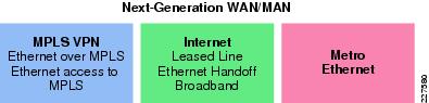
The success of Small Enterprise Design depends on having an effective and better collaborative environment between employees located at different geographic locations. Some of the technologies that enhance this environment are interactive-video, on-demand video, voice and web collaboration, video to mobile devices, and TelePresence. To enable these technologies that foster the collaborative environment, WAN design is a critical consideration. There are several WAN technologies available today to provide WAN services, such as MPLS/VPN, Internet, and Metro Ethernet. See Figure 3-1.
Figure 3-1 WAN Technology Representation
MPLS/VPN
The MPLS/VPN provides Layer-2 or Layer-3 VPN services. It provides the capability to an IP network infrastructure that delivers private network services over a shared network infrastructure. For more information about deploying MPLS/VPN, refer to the following URL: www.cisco.com/go/srnd
Internet
Out of the three WAN technologies, Internet is the cheapest and easiest to deploy. However, to deploy a VPN service over Internet requires an overlay VPN network such as DMVPN to provide secure VPN service.
Metro Ethernet
Metro Ethernet is one of the fastest growing transport technologies in the telecommunications industry. In the current WAN design, it is recommended to use Metro Ethernet Service as WAN transport between remote sites and main office. The following subsection describes the advantages of Metro service.
Why Metro Ethernet Service Is Needed
The deployment of carrier Ethernet services had raced to an astounding $7 billion by 2007* with predictions of more than $30 billion by 2012. This is driven by the following benefits to end users (IT, network, and applications departments) and service providers alike:
•
–
•
–
–
•
–
•
–
•
–
–
Types of Services Available in Metro Ethernet
The following are two popular methods of Metro service:
•
•
EVPL, like Frame Relay, provides multiplexing multiple point-to-point connections over a single physical link. In the case of Frame Relay, the access link is a serial interface to a Frame Relay switch with individual data-link connection identifiers (DLCIs) identifying the multiple virtual circuits or connections. In the case of EVPL, the physical link is Ethernet, typically FastEthernet or Gigabit Ethernet, and the multiple circuits are identified as VLANs by way of an 802.1q trunk.
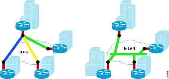
One of the major advantage E-LAN provides is any-to-any connectivity within the Metro area, which allows flexibility. It passes 802.q trunks across the SP network known as Q-in-Q. Figure 3-2 shows the difference between E-line and E-LAN.
Figure 3-2 Different Services Available
WAN Service Deployed in the Small Enterprise Design
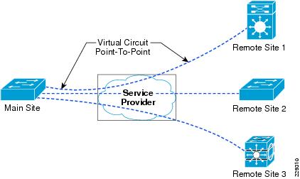
In this version of the guide, E-line with point-to-point service is chosen as the model for connecting remote sites to main site. All the remote sites have a point-to-point connection to the main site. Each remote site is assumed to have 100Mpbs of Metro service to the service provider. As mentioned in the previous section, each circuit is represented by a VLAN using dot1q trunk. Figure 3-3 shows how this is implemented in this design.
Figure 3-3 EVPN Service Used in Remote WAN Architecture
The following is the configuration of the WAN interface at the main site:
interface GigabitEthernet1/1/1description Connected to SP-MPLS-Core-cr24-6500-1switchport trunk native vlan 801switchport trunk allowed vlan 501-550switchport mode trunklogging event trunk-statusload-interval 30carrier-delay msec 0priority-queue outmls qos trust dscpspanning-tree portfast trunkspanning-tree bpdufilter enablespanning-tree guard rootservice-policy output Remote-1to50-Parent-Policy-Maphold-queue 2000 inhold-queue 2000 outAs shown in the above configuration, the link is carrying 50 VLANs, which are connected to 50 small office sites. The solution shown above is one of the ways to deploy WAN service; there are other ways to deploy the WAN service. The next section discusses when to look at alternative to Metro service.
When to Consider WAN Technologies
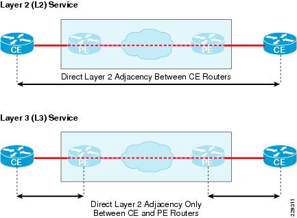
In this design, all the remote sites are connected to the main site using point-to-point links that provide high bandwidth, symmetric traffic flows, and rich media services to all the sites. Since it is a point-to-point circuit, when the number of circuits increases to 1K and beyond, then we need not only to have 1K point-to-point circuits at the main site but also have 1K routing adjacency relationships, which will increase the CPU utilization. Therefore, when the scalability numbers increase more than 1K, an alternative Layer-3 WAN technology such as MPLS/VPN should be considered. MPLS/VPN Layer-3 technology deployments will not require different hardware, but only changing the WAN service. Figure 3-4 shows the routing behavior difference between Layer 2 (Metro service) and Layer 3 (MPLS/VPN service) from the routing protocol perspective.
Figure 3-4 Difference in Routing Adjacency Between Layer 2 and Layer 3 Service
Bandwidth Capacity
This is critical component of the overall WAN design architecture because the application performance largely depends upon guaranteed level of bandwidth at remote sites and the main site. This section primarily discusses the general WAN bandwidth capacity planning and implementation steps.
Planning
To start with, each site must purchase the Metro Ethernet service from local service provider (SP) with bandwidth capacity that can meet the current minimum network load and provides enough flexibility to scale higher in the future, when additional applications need to be added. This bandwidth must be shared based on 4 class QoS model as described in the "Deploying QoS in Network" section on page 2-51 for optimal delivery. Logical bandwidth assignment to each circuit must be symmetric at the remote small office sites and at the main site. A mismatch in bandwidth capacity will force the traffic drop in the SP core due to inconsistent bandwidth service-level agreement.
This design requirement remains consistent for all the remote sites. Depending on large, medium, or small size, the WAN bandwidth capacity may also vary; however, the bandwidth sharing, routing, QoS, multicast etc. principles remains consistent.
Note
Calculating the optimum guaranteed bandwidth required at each remote site and the main site must be done by considering the following factors:
•
•
•
•
•
•
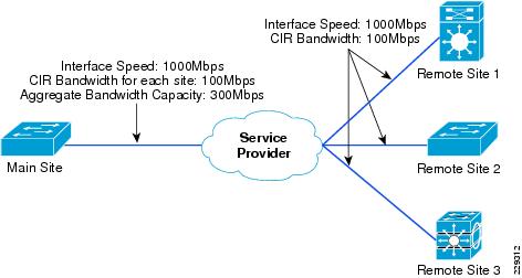
For example, consider a scenario where there are three remote sites and one main site. The CIR required at each remote site is 100Mbps and, because there are three remote sites, the main office needs three virtual circuits each having a CIR of 100Mbs. This also means that the aggregate bandwidth at main office is 300Mbps. Figure 3-5 illustrates this example.
Figure 3-5 Bandwidth Capacity Planning for Three Remote Sites
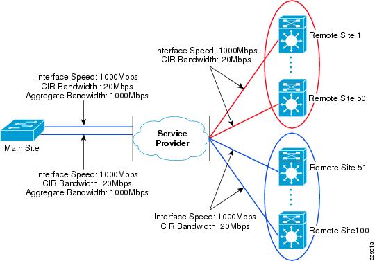
Similarly, if the CIR required at each remote site is 100Mbps and if there are 100 remote sites, then the bandwidth required at main office is 10Gbps. To support an aggregate CIR bandwidth of 10Gbps at main office, we need to think about scalability limits on the WAN aggregation switch. If the aggregated logical connection speed to the remote sites exceed the media capacity on 3750-ME, which is WAN aggregation switch for this design, then there are two approaches to mitigate the problem:
•
•
Implementation
This section discusses how WAN bandwidth was implemented and validated at remote sites and main office of this design. The following are the considerations used to validate this model:
•
•
•
Figure 3-6 shows how this design is validated with 100 remote sites.
Figure 3-6 Bandwidth Capacity Planning for 100 Remote Sites
The next section discusses how to implement an IP addressing structure for the WAN interfaces.
Aggregation Structure
This section describes how to aggregate IP address space at remote sites and the main site on the WAN interface.
For designing IP address spaces for the LAN, refer to "Multicast IP Addressing" section on page 2-43.
As explained in the previous section, all the remote sites are connected to the main site using point-to-point links, which means that every remote site should be on a different subnet. One common method that some customers deploy is using /30 subnets at both ends. However, this would mean that every subnet uses up to four addresses. The recommendation is to use /31 subnets, this way only two addresses are used in every link. The following is a sample configuration for deploying this link at the remote site:
After planning an IP addressing scheme, the next part is to complete a routing design for the WAN connections, which is discussed in the following section.
Routing for WAN Connections
This section discusses how to implement routing on WAN interfaces. The key consideration while designing routing scheme is as follows:
•
10.127.0.0/2610.127.0.64/2610.127.0.128/26...10.127.7.64/26Since the above subnets belong to a particular remote site (the main site pair, they could be summarized as 10.127.0.0/21. The following configuration shows how to perform summarization on the WAN interface, which is Vlan501 in this example:
The next most important component is QoS design, which the following section discusses.
QoS Design
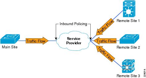
This section discusses how QoS is implemented at the main office and remote sites. With Ethernet defined as the WAN medium, QoS design becomes most important because the router or switch on the WAN edge may believe that it has the complete line rate available for it to transmit. If so, the service provider would start dropping packets due to policers defined at its end. Figure 3-7 shows what may happen without a proper QoS design.
Figure 3-7 Policing at Service Provider Due to Lack of Proper QoS at Main Office and Remote Sites
To prevent packets getting dropped at the service provider network, it is very important to have proper and consistent QoS policies at the remote sites and main site. Having a proper QoS policy would ensure that all the traffic is queued and serviced as per the bandwidth defined. This in turn ensures that packets will not be dropped by the service provider. The following subsections discuss how QoS policies are implemented at the remote and main sites.
QoS Policy at Main Site
As mentioned in the "When to Consider WAN Technologies" section, the main office has several point-to-point circuits to the remote sites, and the number (point-to-point circuits) depends upon the number of remote sites. Therefore, the QoS policy at the main site has the following objectives:
•
•
To accomplish the above objectives, an hierarchical CBWFQ (HCBWFQ) is implemented. For more information about HCBWFQ, refer to "Chapter 4, Medianet QoS Design Considerations" of the Medianet Reference Guide at following URL:
http://www.cisco.com/en/US/docs/solutions/Enterprise/Video/Medianet_Ref_Gd/medianet_ref_gd.html
To implement HCWFQ, the following two policies are needed:
1.
2.
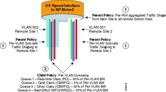
Figure 3-8 shows the representation of hierarchical policy.
Figure 3-8 Hierarchical Policy Implementation at Main Office
Table 3-1 shows how these classes are defined.
Table 3-1 QoS Policies
REAL_TIME
LLQ
30%
GOLD
CBWFQ
5%
SILVER
CBWFQ
30%
DEFAULT
CBWFQ
35%
The following is the configuration of the QoS policy at the main office. For brevity, only configuration for one VLAN is shown.
class-map match-all Remote_Site1 fl This class map would match the traffic going to a
Remote site
description cr2-4507-SS1match vlan 501policy-map Remote-Child-Policy-Map fl This is child policyclass REAL_TIMEprioritypolice cir percent 30 conform-action set-cos-transmit 5 exceed-action drop violate-action dropclass GOLDbandwidth percent 5set cos 3class SILVERbandwidth percent 30set cos 2class class-defaultbandwidth percent 35set cos 0!The following configuration is of the parent policy, which in this design shapes to 20Mbps for each remote site:
Policy Map Remote-1to50-Parent-Policy-Map fl This is parent policy mapClass Remote_Site1shape average 20000000 (bits/sec)service-policy Remote-Child-Policy-Map fl This is child policy mapAfter defining the policies, they are applied to WAN interfaces. The following example shows the configuration of the Metro switch on its WAN interface:
interface GigabitEthernet1/1/1description Connected to SP-MPLS-Core-cr24-6500-1switchport trunk native vlan 801switchport trunk allowed vlan 501-550switchport mode trunklogging event trunk-statusload-interval 30carrier-delay msec 0priority-queue outmls qos trust dscpspanning-tree portfast trunkspanning-tree bpdufilter enablespanning-tree guard rootmax-reserved-bandwidth 100service-policy output Remote-1to50-Parent-Policy-Map fl The policy-maphold-queue 2000 inhold-queue 2000 outAfter completing the QoS policy at main office, we need to define the QoS policy at remote sites. The following subsection describes how to define QoS policy at the remote site.
QoS Policy at Remote Site
At the remote sites, the objectives are similar to the one at main site, which is to ensure that 20Mbps is the aggregate traffic leaving out the switch and the ingress traffic is queued in 4 classes. However, the implementation is different from the main office due to lack of hierarchical QoS support on the particular switch deployed at the remote site. It is however possible to have a line card with the capability to do HCBWFQ, if it is needed. The following configuration shows how to do QoS policy when the device does not support HCBWFQ.
The first step is to queue the ingress traffic in the four queues. Table 3-2 shows the queues and the bandwidth allocated.
Table 3-2 QoS Policies for Remote Site
REAL_TIME
Per-class
6mbps
GOLD
Per-class
1mbps
SILVER
Per-class
7mpbs
DEFAULT
Per-class
6mbps
The following is configuration of egress interface on the remote site:
interface GigabitEthernet1/1description Connected to MetroE-Core-cr25-6500-1switchport trunk encapsulation dot1qswitchport trunk native vlan 801switchport trunk allowed vlan 501switchport mode trunklogging event link-statusload-interval 30carrier-delay msec 0qos trust dscpudld port disabletx-queue 1bandwidth 1 mbpstx-queue 2bandwidth 7 mbpstx-queue 3bandwidth 6 mbpspriority hightx-queue 4bandwidth 6 mbpsno cdp enablespanning-tree portfast trunkspanning-tree bpdufilter enablespanning-tree guard rootservice-policy output WAN-EGRESS-PARENTThe above configuration ensures that each class of the traffic is queued as shown in Table 3-2. However, the bandwidth only ensures the minimum amount of bandwidth available. It does not control the upper threshold, which needs to be 20Mbs in our solution. Therefore, to ensure that the traffic on the egress interface does not exceed 20Mps, WAN-EGRESS-PARENT policy is used to police the traffic to 20Mbps. The following is configuration of the WAN egress policy:
cr35-4507-SS1#show policy-map WAN-EGRESS-PARENTPolicy Map WAN-EGRESS-PARENTClass class-defaultpolice 20 mbps 1000 byte conform-action transmit exceed-action dropservice-policy WAN-EGRESS-CHILDcr35-4507-SS1#