-
Wireless and Network Security Integration Solution Design Guide
-
Preface
-
Solution Overview
-
Solution Architecture
-
802.11 Security Summary
-
Cisco Unified Wireless Network Architecture— Base Security Features
-
Wireless NAC Appliance Integration
-
Secure Wireless Firewall Integration
-
CSA for WLAN Security
-
Cisco Wireless and Network IDS/IPS Integration
-
CS-MARS Integration for Cisco Unified Wireless
-
Glossary
-
Table Of Contents
Cisco Wireless and Network IDS/IPS Integration
Roles of Wireless and Network IDS/IPS in WLAN Security
Complementary Roles of Wireless and Network IDS/IPS
Collaborative Role of Cisco WLC and Cisco IPS
How Cisco WLC and IPS Collaboration Works
Cisco WLC and IPS Synchronization
WLC Enforcement of a Cisco IPS Host Block
Cisco IPS Host Block Retraction
Cisco Unified Wireless and IPS Integration
IPS Deployment and Integration
Enabling Cisco WLC and Cisco IPS Collaboration
Enabling Cisco WLC and IPS Collaboration Monitoring
Enabling WLC Local Logging of WLAN Client Block Events
Enabling SNMP Traps for WLAN Client Block Events
Enabling WCS Cross-WLC Monitoring of WLAN Events
Enabling CS-MARS Monitoring of WLAN Events
Cisco IPS Host Block Activation and WLC Enforcement
Monitoring Cisco WLC and IPS Collaboration
Verifying Cisco WLC and IPS Communication Status
Viewing WLAN Client Block Events
WLC Local Logging of WLAN Client Block Events
SNMP Reporting of WLAN Client Block Events
IPS Events Related to Host Block Events
WLC CLI Reporting of WLAN Client Block Events
IPS CLI Reporting of WLAN Client Block Events
WCS Cross-WLC Monitoring of WLAN Client Block Events
Consolidated Shunned Clients List
Consolidated Excluded Client Events List
General Guidelines for Cisco Wireless and Network IDS/IPS Integration
Cisco WLC and IPS Collaboration Operational Details
Cisco IPS Block versus Deny Actions
Cisco IPS and WLC Integration Dependencies
Test Bed Hardware and Software
Cisco Wireless and Network IDS/IPS Integration
A secure Cisco Unified Network, featuring both wired and wireless access, requires an integrated, defense-in-depth approach to security, including cross-network threat detection and mitigation that is critical to effective and consistent policy enforcement. Wireless and network IDS/IPS are both critical elements of network security, performing complementary roles in threat detection and mitigation.
This chapter outlines these complementary roles of wireless and network Intrusion Detection System/Intrusion Prevention System (IDS/IPS), along with how they are fulfilled by the Cisco WLAN Controller (WLC) and Cisco IPS platforms respectively. This chapter also presents how, by enabling collaboration between these two Cisco platforms, they can be used to provide a simple, but effective, automated threat mitigation tool.
Guidelines for deploying and integrating Cisco IPS with a Cisco Unified Wireless Network are provided, along with how to enable WLC and IPS collaboration for automated threat mitigation.
Software implementation, screenshots, and behavior referenced in this chapter are based on the releases listed in Test Bed Hardware and Software. It is assumed that the reader is already familiar with both the Cisco Unified Wireless Network and Cisco IPS.
Note
This chapter addresses only IDS/IPS integration features specific to the Cisco WLC and Cisco IPS platforms.
Roles of Wireless and Network IDS/IPS in WLAN Security
Cisco IPS are network-based platforms designed to accurately identify, classify, and stop malicious traffic, including worms, spyware, ad ware, network viruses, application abuse, and policy violations. This is achieved through detailed traffic inspection at Layers 2 through 7.
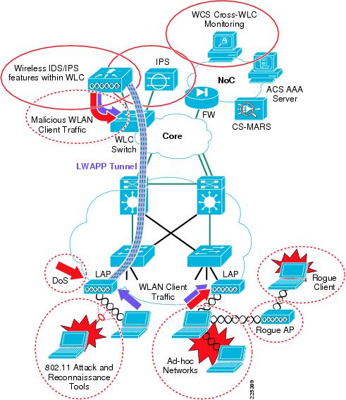
The wireless IDS/IPS features of the Cisco WLC and the network IDS/IPS features of the Cisco IPS platforms are key elements of an integrated, defense-in-depth approach to WLAN security, performing complementary and collaborative roles in threat detection and mitigation on a WLAN.
Complementary Roles of Wireless and Network IDS/IPS
The complementary roles of wireless and network IDS/IPS enable the same principles and policies of threat detection and mitigation employed on a wired network to be extended to a WLAN.
Wireless and network IDS/IPS are complementary in the following ways:
•
•
Figure 8-1 Wireless and Network IDS/IPS for WLAN Threat Detection and Mitigation
A summary of the key complementary roles and features of the Cisco WLC and Cisco IPS in WLAN threat detection and mitigation is presented in Table 8-1.
Table 8-1 WLAN Threat Detection and Mitigation Roles
Wireless IDS/IPS features of WLC1
Rogue AP
Detection, location, and containment, including traceback on the wired network
Rogue client
Detection and containment
Wireless ad-hoc network
Detection and containment
802.11 DoS
802.11 DoS attack signatures2
Cisco Management Frame Protection3
802.11 attack tools
802.11 reconnaissance signatures2
Excessive 802.11 associations and authentications
Detection, tracking and containment through client exclusion settings
IP theft and re-use
Detection and containment
RF interference
Dynamic radio resource management
Network IDS/IPS features of Cisco IPS platform
Malicious WLAN client traffic
For example, worms, viruses, application abuse, spyware, adware, and so on, as well as policy violations4
Signature-based detection, identification and classification of malicious traffic
Range of response actions available including alert, SNMP trap, packet drop, connection block, and host block
1 Wireless IDS/IPS features are provided by the Cisco WLC. The adaptive wireless IPS features of the Cisco Mobility Services Engine (MSE) are not addressed in this guide.
2 The WLC and WCS include standard signatures but also support custom signatures that can be developed to extend their threat detection capabilities.
3 Cisco Management Frame Protection is a unique feature that provides signature-based management frame authentication that can be used to address 802.11-based DoS attacks but also enables easy identification of a rogue AP. For more information on Management Frame Protection, refer to Management Frame Protection, page 4-16.
4 A Cisco IPS platform deployed in a WLAN environment performs the same monitoring, detection, and mitigation of malicious traffic for WLAN clients as it does for wired clients, and the same policies are generally applied.
Wireless IDS/IPS features are addressed in more detail in Cisco Unified Wireless Network Architecture— Base Security Features, page 4-1 and Wireless IDS, page 4-9.
For more information on Cisco IPS refer to Reference Documents.
Collaborative Role of Cisco WLC and Cisco IPS
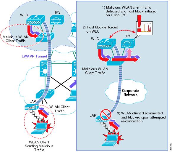
Collaboration of the Cisco WLC and Cisco IPS provides a simple, but effective, automated threat mitigation tool that offers centralized control with local enforcement, right on the access edge. This collaboration requires no additional hardware and very simple configuration, using the deployment of these two platforms to further enhance their value in threat detection and mitigation (see Figure 8-2).
Figure 8-2 Cisco WLC and IPS Integration for Automated Threat Mitigation
The Cisco IPS monitors client traffic and, upon identifying threats and anomalies, triggers a client disconnect through creation of a host block. For a WLAN client, this mitigation action is automatically enforced by the WLC through collaboration with the Cisco IPS. The client is removed from the network at the access edge and denied re-entry until the host block is either removed or times out. Cisco WLC and Cisco IPS collaboration thus offers operational staff an additional automated threat mitigation tool that can be employed when anomalous behavior is detected.
How Cisco WLC and IPS Collaboration Works
Collaboration between a Cisco WLC and Cisco IPS provides an automated threat mitigation tool, enabling host block activation on an IPS to be enforced directly on the WLAN. This collaboration involves the following key operational elements:
•
•
•
Cisco WLC and IPS Synchronization
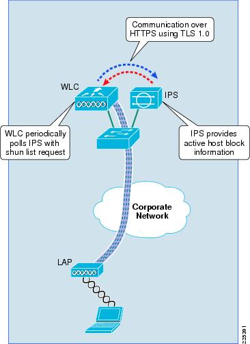
A Cisco WLC and IPS synchronize active host block information by the WLC periodically polling the IPS with a shun list request. The Cisco IPS responds with the active host block list (see Figure 8-3).
Figure 8-3 Cisco WLC and IPS Synchronization
Note the following:
•
•
•
WLC Enforcement of a Cisco IPS Host Block
Automated threat mitigation is provided through collaboration of a Cisco WLC and IPS, enabling a Cisco IPS host block to be passed to and, in the case of a matching WLAN client, enforced by the Cisco WLC.
When anomalous activity in client traffic is detected by an IPS, subsequent investigation may result in a decision to block the client generating these anomalies. This can be initiated on a Cisco IPS and enforced, either directly on the IPS, or through collaboration with another network device, such as a WLC. Enforcement on the Cisco IPS is done through a deny action and enforcement on another network device is activated through a block action.
For more information on the Cisco IPS deny and block actions, refer to Cisco IPS Block versus Deny Actions.
Note
To enable enforcement of a host block on another network device, including a WLC, a host block can be activated on a Cisco IPS by one of the following methods:
•
•
•
Note
The WLC receives the IPS host block information upon its next poll of the IPS for the shun list. If a WLAN client that matches the host block information is associated with the WLC, the WLC enforces this host block by creating a WLAN client exclusion for that host. The WLAN client is disconnected from the WLAN and blocked from reconnecting as long as the host block action is active.
WLC enforcement of a Cisco IPS host block for a WLAN client is shown in Figure 8-4.
Figure 8-4 WLC Enforcement of a Cisco IPS Host Block
The following are the WLC enforcement steps for a Cisco IPS host block:
Step 1
Step 2
Step 3
Step 4
Step 5
Step 6
Step 7
Step 8
Step 9
Step 10
Cisco IPS Host Block Retraction
Retraction of a Cisco IPS host block occurs based on one of the following events:
•
•
When a Cisco IPS host block is retracted, the WLC receives the updated active host block list on its next poll of the IPS and updates its shunned client list.
The steps performed by a WLC upon retraction of a Cisco IPS host block for a WLAN client are outlined below:
Step 1
Step 2
Step 3
Step 4
Step 5
Cisco Unified Wireless and IPS Integration
This section outlines the steps required to integrate a Cisco IPS with a Cisco Unified Wireless Network, along with how to provide a simple, but effective, automated threat mitigation tool by enabling collaboration between a Cisco WLC and a Cisco IPS. This collaboration requires no additional hardware and very simple configuration.
The configuration of a Cisco IPS is illustrated using Cisco IDS Device Manager (IDM). The configuration of the Cisco WLC is illustrated using the GUI of the WLC.
IPS Deployment and Integration
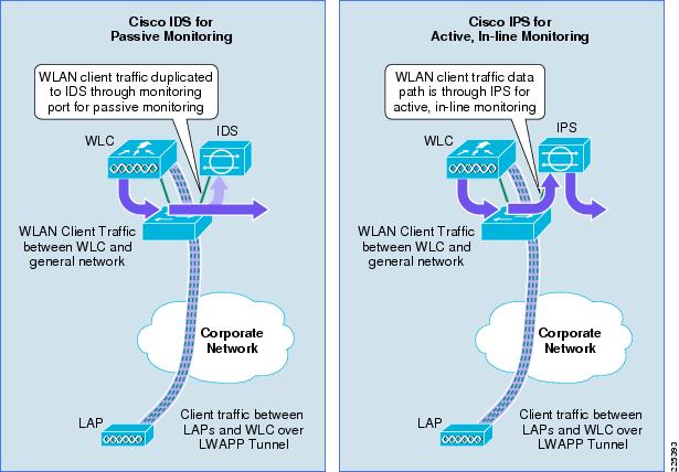
On a Cisco Unified Wireless Network, all WLAN client traffic enters the corporate network through the WLC. This provides the ideal location to perform threat detection and mitigation on this traffic, and a simple integration point for a Cisco IPS. (See Figure 8-5.)
Figure 8-5 Cisco Unified Wireless and IPS Deployment Modes
A Cisco IPS can be deployed either as an IDS, employing promiscuous mode passive monitoring, or as an IPS, employing inline mode active monitoring. For the purposes of collaboration with a Cisco WLC, a Cisco IPS can be deployed in either IDS or IPS mode. Enforcement of a host block is done by the WLC, not the IPS; therefore, the sensor is not required to be inline. Consequently, the choice of IPS deployment mode is a general network design choice.
For more information on IPS deployment modes refer to Cisco IPS Deployment Modes.
Note the following:
•
•
•
Detailed IPS design guidance can be found in the documents listed in Reference Documents.
Enabling Cisco WLC and Cisco IPS Collaboration
Collaboration between a Cisco WLC and a Cisco IPS requires completion of the following simple steps:
•
•
•
•
Detailed instructions on how to implement each step are outlined below.
The first step in enabling Cisco WLC and Cisco IPS collaboration is to enable the WLC to retrieve active host block information from the IPS.
Step 1
This enables the WLC to obtain the active host block information from the IPS.
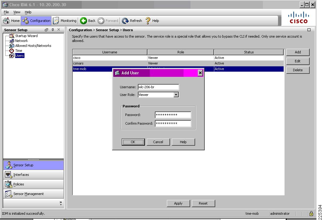
On the IDM, go to Configuration -> Sensor Setup -> Users. Add a new user with the user role Viewer and configure a password. (See Figure 8-6.)
Figure 8-6 Create a User Account on Cisco IPS for a WLC
Note the following:
•
•
•
•
Step 2
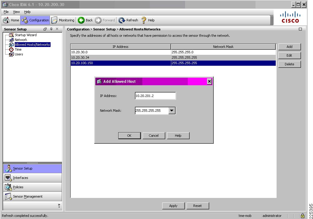
On IDM v6.1, go to Configuration -> Allowed Hosts/Networks. Add an allowed host with the WLC source IP address and network mask. (See Figure 8-7.)
Figure 8-7 Define the WLC as an Allowed Host on Cisco IPS
Note the following:
•
Step 3
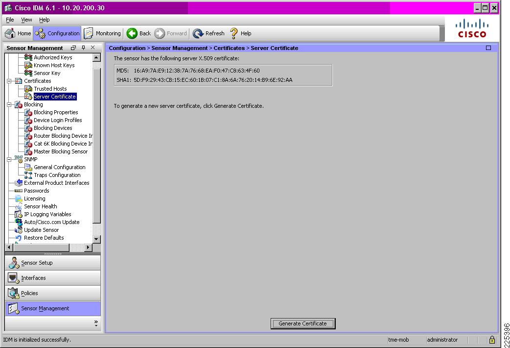
The TLS fingerprint is the server-side X.509 certificate of the IPS. This fingerprint is used in TLS 1.0 to authenticate the server and to secure communication between the WLC and the IPS. On the IDM, go to Configuration -> Sensor Setup -> Certificates -> Server Certificate. (See Figure 8-8.)
Figure 8-8 Sample TLS Fingerprint of a Cisco IPS
The TLS fingerprint may also be retrieved on the CLI of a Cisco IPS by entering the following command:
show tls fingerprintA sample TLS fingerprint is as follows:
ips-3845-2# show tls fingerprintMD5: 16:A9:7A:E9:12:38:7A:76:68:EA:F0:47:C8:63:4F:60SHA1: 5D:F9:29:43:CB:15:EC:60:1B:07:C1:8A:6A:76:20:14:B9:6E:92:AAStep 4
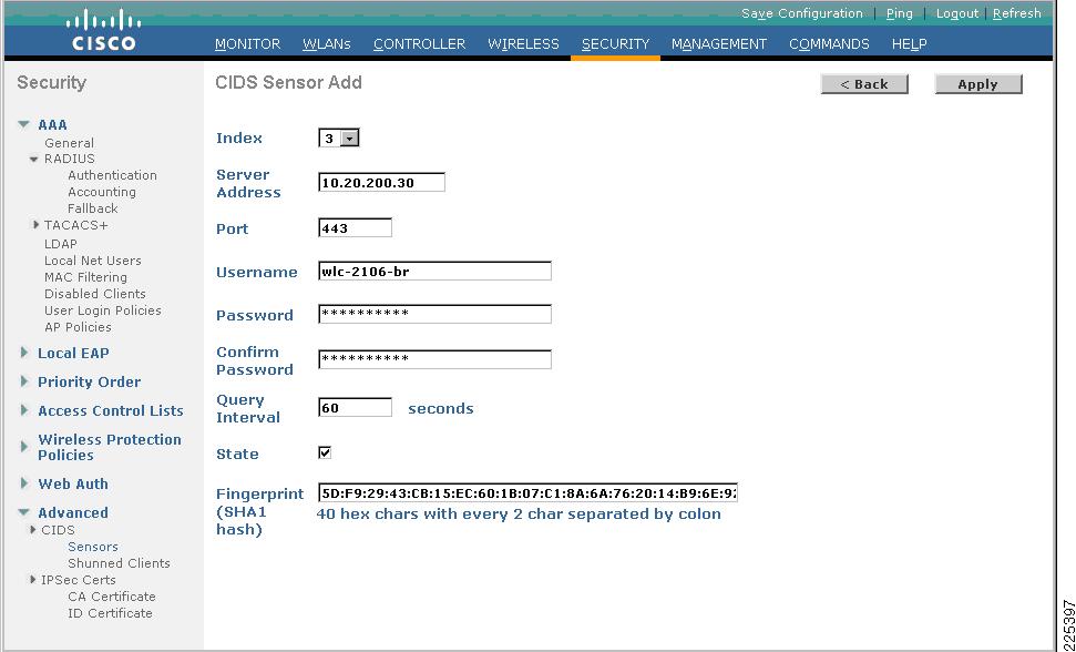
On the WLC, go to Security -> CIDS -> Sensors. Add a new CIDS sensor with the IP address of the IPS. Enter the username and password of the WLC user account created on the IPS, as completed in Step 1. Check the State box to activate the sensor, enter the TLS fingerprint of the IPS and select the Apply button. (See Figure 8-9.)
Figure 8-9 Define the IPS as a CIDS Sensor on the WLC
Note the following:
•
•
•
•
•
•
Step 5
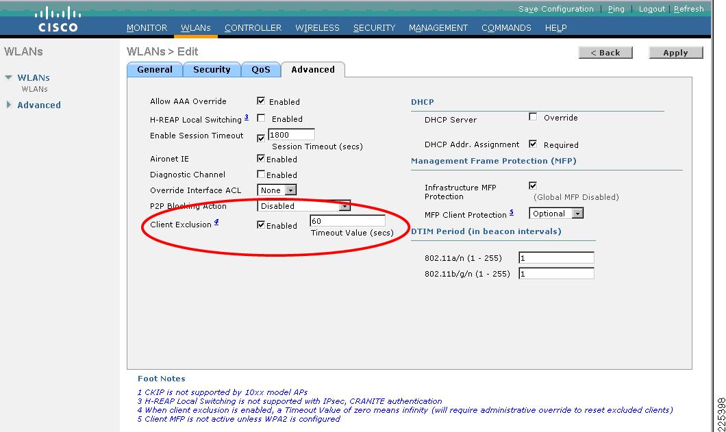
On the WLC, go to WLANs to access the WLAN profiles. Select the particular WLAN profile on which client blocking is to be enabled and go to the Advanced tab. Next to Client Exclusion, ensure that the Enabled checkbox is checked. (See Figure 8-10.)
Figure 8-10 Enable Client Exclusion on each WLAN to Support WLAN Client Blocking Enforcement
Note the following:
•
•
•
•
•
•
Enabling Cisco WLC and IPS Collaboration Monitoring
Monitoring of network activity is critical to effective network management. This chapter provides details on how to enable monitoring of Cisco WLC and IPS collaboration through:
•
•
•
•
Enabling WLC Local Logging of WLAN Client Block Events
The WLC offers a local message log that can be accessed either through the WLC GUI or on the WLC CLI. The logging of WLAN client block events to this message log requires the WLC log level to be set to a minimum security level of 1, which equates to Alerts. A WLC will then generate a local message log entry upon a WLAN client being blocked as a result of an IPS host block, including the IP address received from the IPS and the associated client's MAC address.
If visibility is required into a WLC denying client association due to a client exclusion, the WLC log level must be set to a minimum severity level of 4, which equates to Warnings. This entry is generated with a WLAN client block event upon a blocked client subsequently attempting to associate while an active client exclusion exists for its MAC address.
The logging levels required for the different logging options are summarized in Table 8-2.
Warning
The default buffered and console log level is Critical, with a severity level of 2. This default setting will log WLAN client block events enforced as a result of a Cisco IPS host block.
The parameters to define the log level are:
•
Defines the log level for the WLC GUI Message log
•
Defines the log level for the WLC CLI log
In previous releases of the WLC, the parameter Message Log Level defines the log level for both the GUI and the CLI. The setting Significant System events enables logging of WLAN client block events.
The following steps describe how to configure the log levels to obtain visibility into WLAN client block events:
Step 1
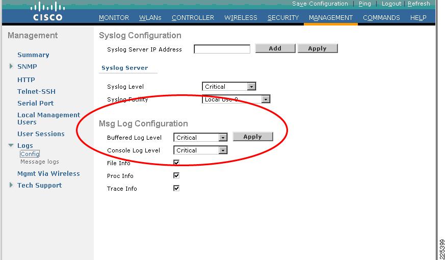
On the WLC, go to Management -> Logs -> Config. Set the log level to Critical for both the buffered and the console parameters. Enforce any changes by clicking Apply. (See Figure 8-11.)
Figure 8-11 WLC Local Logging Level to include WLAN Client Block Events
Enabling SNMP Traps for WLAN Client Block Events
Enforcement of an IPS host block is enforced by a WLC through automatic creation of a client exclusion. Consequently, in order to generate an SNMP trap upon this event occurring, SNMP traps for client exclusion must be enabled on the WLC.
Step 1
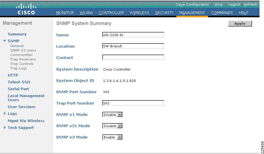
On the WLC, go to Management -> SNMP -> General. Ensure, at a minimum, that the system name and the correct trap port number are defined, and disable any SNMP versions not required. (See Figure 8-12.)
Figure 8-12 Verify the General SNMP Parameters on the WLC
Note the following:
•
•
•
•
•
•
•
For more information on securing SNMP access, refer to the Network Security Baseline (see Reference Documents).
Step 2
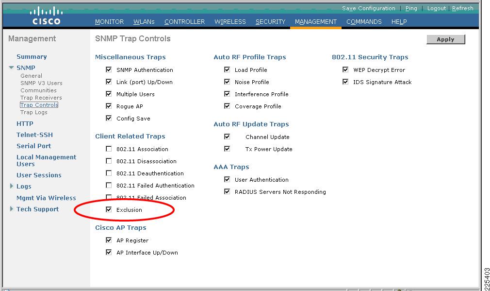
On the WLC, go to Management -> SNMP -> Trap Controls. Under Client Related Traps, ensure that the Exclusion checkbox is checked. (See Figure 8-13.)
Figure 8-13 Enable SNMP Traps for Client Exclusion on the WLC
Enabling WCS Cross-WLC Monitoring of WLAN Events
WCS offers a consolidated view of cross-WLC events that is invaluable for visibility into activity across the entire Unified Wireless Network. The WCS leverages SNMP traps sent by each WLC to generate these consolidated views. Consequently, each WLC must be configured to send SNMP traps to the WCS.
Enabling WCS monitoring of cross-WLC events requires the following key elements:
•
–
–
–
–
•
–
Detailed instructions on how to configure each of these elements are outlined below. WCS supports SNMP v3; therefore, the configuration is shown for SNMP v3. SNMP v1 and v2c are supported, but SNMP v3 is the most secure implementation of SNMP and is recommended where supported.
Step 1
On the WLC, go to Management -> SNMP -> General (see Figure 8-14). For details, refer to Enabling SNMP Traps for WLAN Client Block Events.
Figure 8-14 Verify the General SNMP Parameters on the WLC
This example leverages the SNMP v3 support of WCS; therefore, SNMP v3 mode must be enabled.
Step 2
On the WLC, go to Management -> SNMP -> Trap Controls (see Figure 8-15). For an SNMP trap to be generated upon a WLAN client host block event, ensure traps are enabled for exclusion. For details, refer to Enabling SNMP Traps for WLAN Client Block Events.
Figure 8-15 Verify the SNMP Trap Controls on the WLC
Step 3
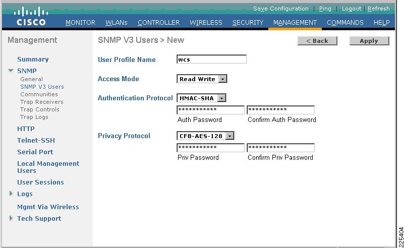
On the WLC, go to Management -> SNMP -> SNMP V3 Users. Select New and define a user profile name for the WCS. Set the access mode drop-down box to Read Write if the WCS is to be granted the ability to modify the WLC configuration. Define the authentication and privacy passwords then click Apply. (See Figure 8-16.)
Figure 8-16 Define the WCS as an SNMPv3 User on the WLC
Note the following:
•
•
•
Step 4
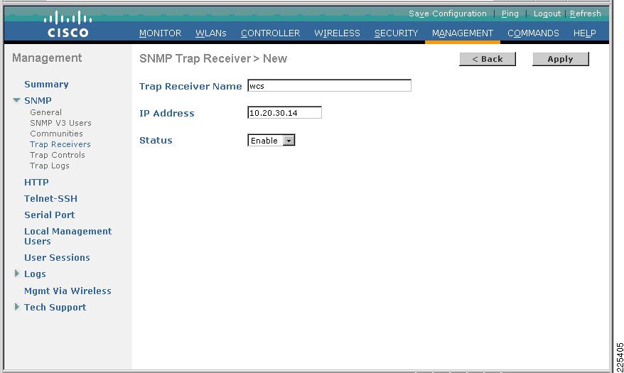
On the WLC, go to Management -> SNMP -> Trap Receivers. Select New and define a name for the WCS, along with its IP address . Set the status drop-down box to Enable and click Apply. (See Figure 8-17.)
Figure 8-17 Define the WCS as an SNMP Trap Receiver on each WLC
Step 5
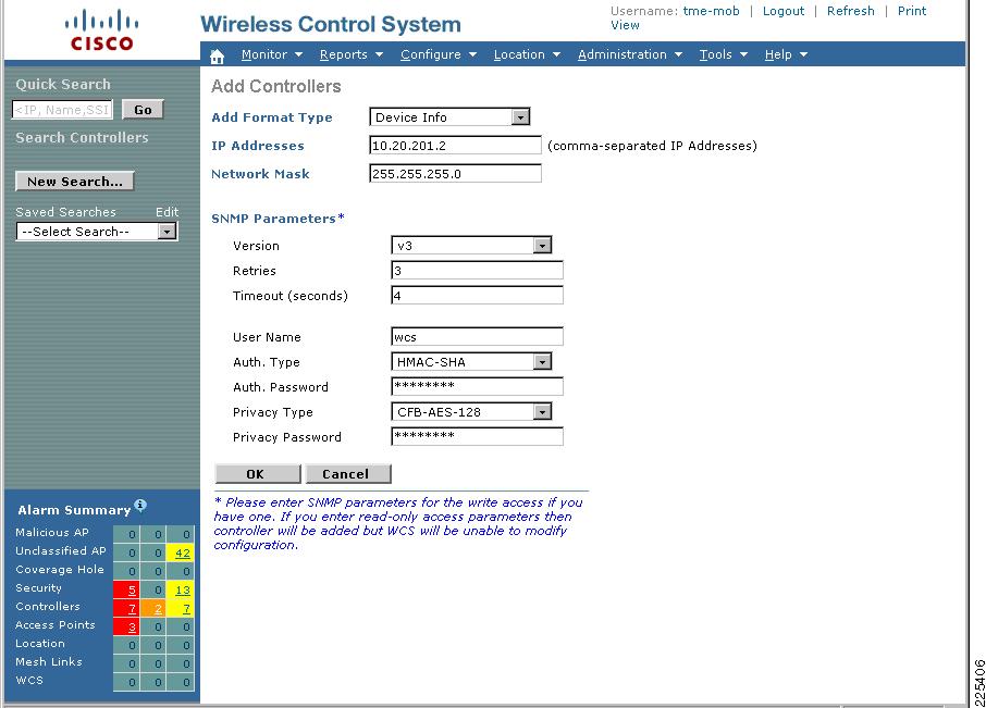
On the WLC, go to Configure -> Controllers. Either add a controller if it does not exist or click on a controller already defined to modify the SNMP parameters. See Figure 8-18.
Figure 8-18 Define each WLC and its SNMP Parameters on the WCS
Click OK and the WCS will attempt to discover the WLC and retrieve its properties.
Note the following:
•
Enabling CS-MARS Monitoring of WLAN Events
CS-MARS provides cross-network anomaly detection and correlation that is critical to effective threat detection and mitigation. This visibility can be extended to include the WLAN by integrating CS-MARS with a Cisco Unified Wireless Network. For detailed information, refer to Chapter 9, "CS-MARS Integration for Cisco Unified Wireless."
Cisco IPS Host Block Activation and WLC Enforcement
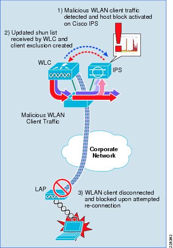
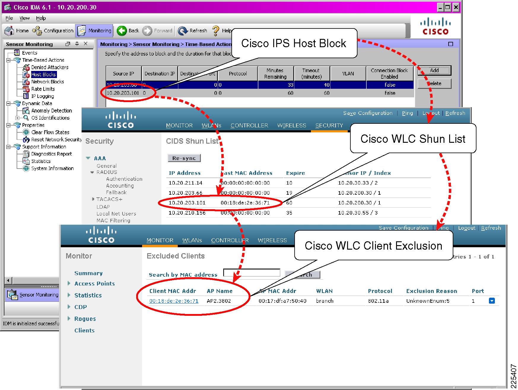
This section illustrates a WLAN client block being activated through a manual host block on a Cisco IPS and automatically enforced on the WLC through a client exclusion. The key steps involved are illustrated in Figure 8-19.
Figure 8-19 Cisco IPS Host Block Activation and WLC Enforcement
Before attempting a WLAN client block, verify that the WLC is able to successfully poll the Cisco IPS and receive a response to its shun list request. For details, refer to Verifying Cisco WLC and IPS Communication Status.
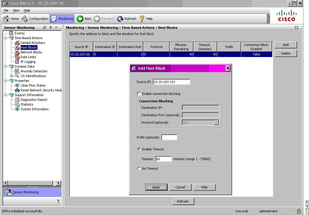
Step 1
On IDM, go to Monitoring -> Time-Based Actions -> Host Blocks. Add a new host block with the source IP address of the WLAN client to be blocked and define the timeout. Click Apply. (See Figure 8-20.)
Figure 8-20 Initiating a Client Block on a Cisco IPS
Note the following:
•
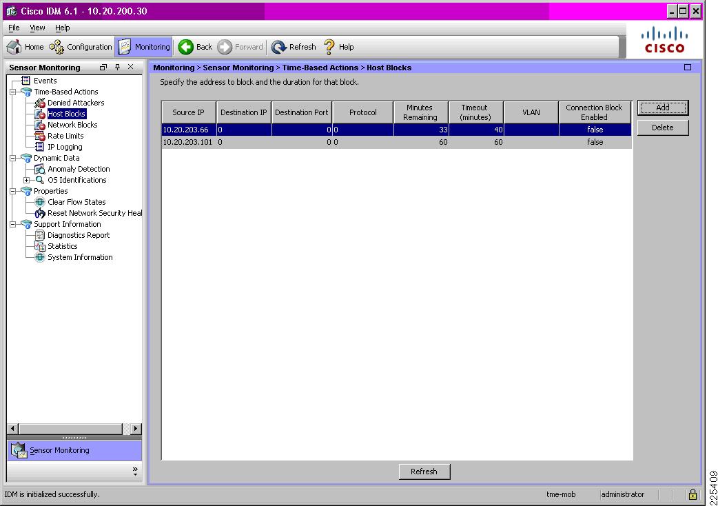
A blocked client subsequently appears in the list of host blocks on that particular IPS. (See Figure 8-21.)
Figure 8-21 Sample List of Host Blocks on a Cisco IPS
Note the following:
•
•
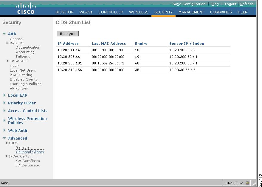
Step 2
Figure 8-22 Sample CIDS Shun List on a WLC
Note the following:
•
•
•
Step 3
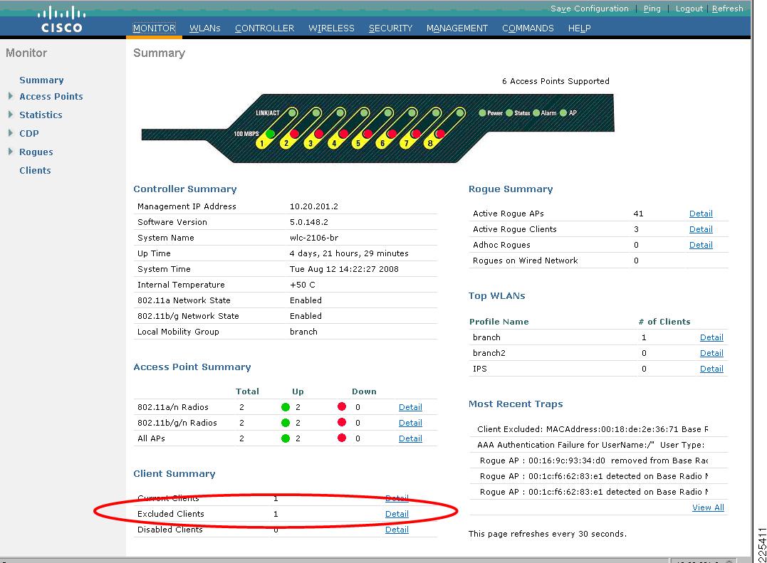
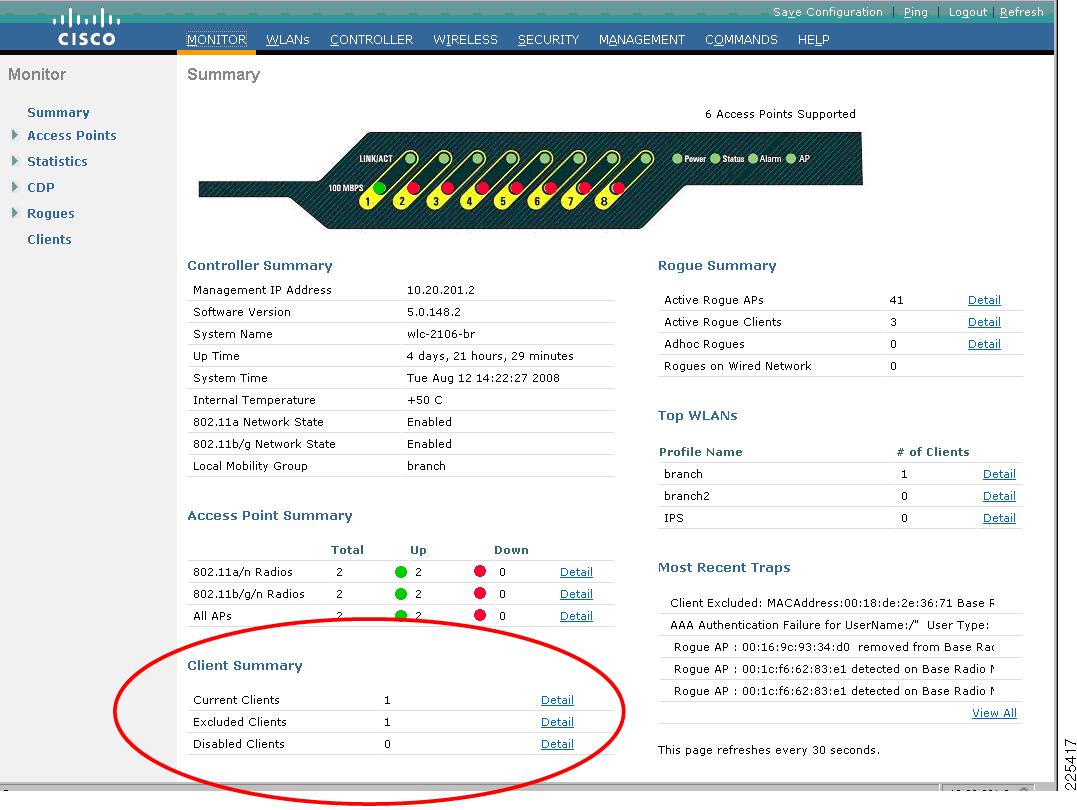
To view all client exclusions currently in place on a WLC, along with the reason for the exclusion, go to Monitor -> Summary and click on Detail next to Excluded Clients under the Client Summary section. (See Figure 8-23.)
Figure 8-23 WLC Monitor Summary screen with Excluded Clients Detail Link
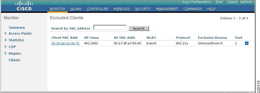
The Excluded Clients list is subsequently displayed. (See Figure 8-24.)
Figure 8-24 Sample Excluded Client List Showing an IPS Host Block
Note the following:
•
•
•
•
•
Monitoring Cisco WLC and IPS Collaboration
Verifying Cisco WLC and IPS Communication Status
Successful communication between a Cisco WLC and IPS can be verified through any of the following interfaces:
•
•
•
•
Once successful communication between a Cisco WLC and a Cisco IPS has been verified, the automated threat mitigation tool enabled by this collaboration is available to operational staff.
WLC GUI
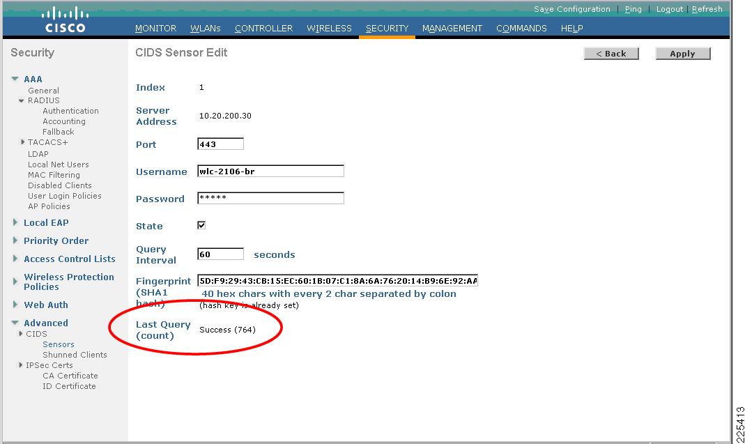
On the WLC GUI, the current status of communication with a particular Cisco IPS can be seen by going to Security -> Advanced -> CIDS -> Sensors and clicking on the Index number of the particular sensor. The Last Query field will indicate "Success" if the WLC and IPS are able to successfully communicate. (See Figure 8-25.)
Figure 8-25 Verifying Communication Status between a WLC and a Cisco IPS on the WLC GUI
WLC CLI
On the WLC CLI, communication with a Cisco IPS can be seen by following these steps:
Step 1
Step 2
debug wps cids enableDebugs automatically appear on the screen as soon as an event occurs.
The following is a sample of a successful WLC poll of a Cisco IPS with a shun list request:
Tue Aug 12 14:21:43 2008: cidsProcessSdeeQuery: ip=10.20.200.30,port=443 state=1
interval=60
Tue Aug 12 14:21:43 2008: cidsQuerySend: https://10.20.200.30:443/cgi-bin/transaction-server?command=getShunEntryListTue Aug 12 14:21:43 2008: curlHandle is bbd422cTue Aug 12 14:21:43 2008: Perform on curlHandle bbd422c ...Tue Aug 12 14:21:43 2008: Response code is 0Tue Aug 12 14:21:43 2008: xmlDoc buffer freedTue Aug 12 14:21:43 2008: Parser cleanedStep 3
debug wps cids disableIDM GUI
The IDM tool can be used to view events generated by the Cisco IPS during communication with a Cisco WLC.
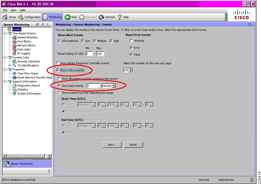
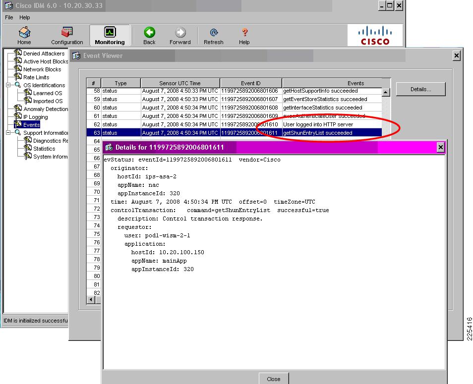
On the IDM, go to Monitoring -> Events.
Enable Show status events, define a short timeframe for Show past events (shown in Figure 8-26 for 3 minutes), and select View.
Figure 8-26 Viewing Cisco WLC and IPS Communication Events on the IDM
In the IDM Event Viewer screen, the related events generated as a result of successful communication will depend upon the IPS software release, as outlined below:
•
Two related entries generated: one for the event User logged into HTTP server and another for the event getShunEntryList succeeded.
•
By default, just one entry generated for the event User logged into HTTP server. In order to see the getShunEntryList event and view the status of a shun-list request, logging of control transactions must be enabled on the IPS CLI. For more information, refer to IPS CLI.
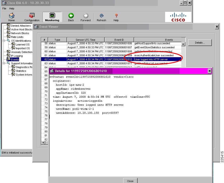
Double-click on an event to see the details, including which WLC logged into the IPS and whether the shun list request was successfully processed. See Figure 8-27 and Figure 8-28.
Figure 8-27 WLC Login to a Cisco IPS Event on the IDM
Figure 8-28 Successful Retrieval of the Shun List by the WLC Event on the IDM
IPS CLI
On the IPS CLI, communication with a particular Cisco WLC can be seen by following these steps:
Step 1
Step 2
ips-3845-2# show events past 0:03 | include 10.20.201.2The following is a sample of a successful WLC login to the IPS and retrieval of the shun list:
evStatus: eventId=1199725892006801610 vendor=Ciscooriginator:hostId: ips-asa-2appName: cidwebserverappInstanceId: 320time: 2008/08/07 16:50:34 2008/08/07 16:50:34 UTCloginAction: action=loggedIndescription: User logged into HTTP serveruserName: pod1-wism-2-1userAddress: port=60597 10.20.100.150evStatus: eventId=1199725892006801611 vendor=Ciscooriginator:hostId: ips-asa-2appName: nacappInstanceId: 320time: 2008/08/07 16:50:34 2008/08/07 16:50:34 UTCcontrolTransaction: command=getShunEntryList successful=truedescription: Control transaction response.requestor:user: pod1-wism-2-1application:hostId: 10.20.100.150appName: mainAppappInstanceId: 320
Note
ips-3845-2(config)# service loggerips-3845-2(config-log)# event-storeips-3845-2(config-log-eve)# status-event-logging-categories controlTransaction enabled trueOnce successful communication has been verified, this level of logging should be disabled, unless specifically required, as shown below:
ips-3845-2(config)# service loggerips-3845-2(config-log)# event-storeips-3845-2(config-log-eve)# status-event-logging-categories controlTransaction enabled falseFor more information, refer to the IPS documentation (see Cisco IPS).
Viewing WLAN Client Block Events
WLC Local Logging of WLAN Client Block Events
If a WLC is configured with local logging set to a minimum security level of 1, a WLC will record WLAN client block events enforced as a result of an IPS host block. For details on configuring local logging, refer to Enabling WLC Local Logging of WLAN Client Block Events.
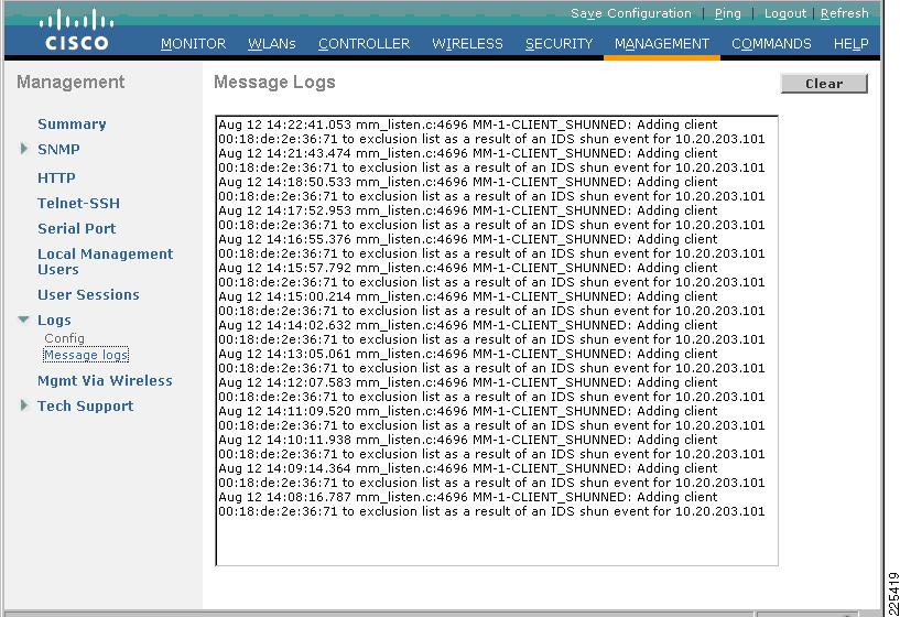
WLC Local Log Format for a WLAN Client Block
The general format of a local message log entry generated by a WLC upon enforcement of a WLAN client block is as follows:
mm_listen.c:4696 MM-1-CLIENT_SHUNNED: Adding client 00:18:de:2e:34:ca to exclusion list as
a result of an IDS shun event for 10.20.205.51
WLC Local Log
The WLC local log can be viewed under Management -> Logs -> Message Logs. (See Figure 8-29.)
Figure 8-29 WLC Local Log Showing a WLAN Client Block Event
Note the following:
•
•
SNMP Reporting of WLAN Client Block Events
If SNMP traps are enabled for client exclusion, an SNMP trap is generated upon a WLC implementing a WLAN client shun to enforce an IPS host block. These SNMP traps can be used by WLC, WCS, CS-MARS, and general SNMP management station. For details on enabling SNMP, refer Enabling SNMP Traps for WLAN Client Block Events.
The WLC GUI reports SNMP traps in two locations:
•
•
SNMP Trap Format for a WLAN Client Block
The general format of an SNMP trap generated by a WLC upon enforcement of a WLAN client block is as follows:
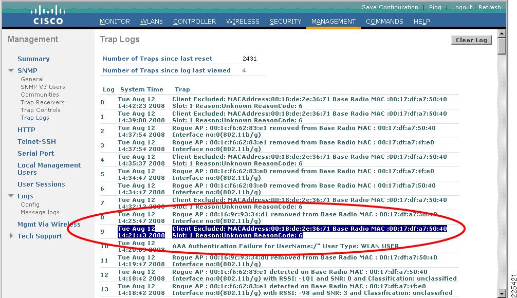
Client Excluded: MACAddress:00:18:de:2e:36:71 Base Radio MAC :00:17:df:a7:50:40 Slot: 1
Reason:Unknown ReasonCode: 5
In this example, Reason:Unknown and ReasonCode: 5 indicate that the exclusion event was generated as a result of an IPS host block.
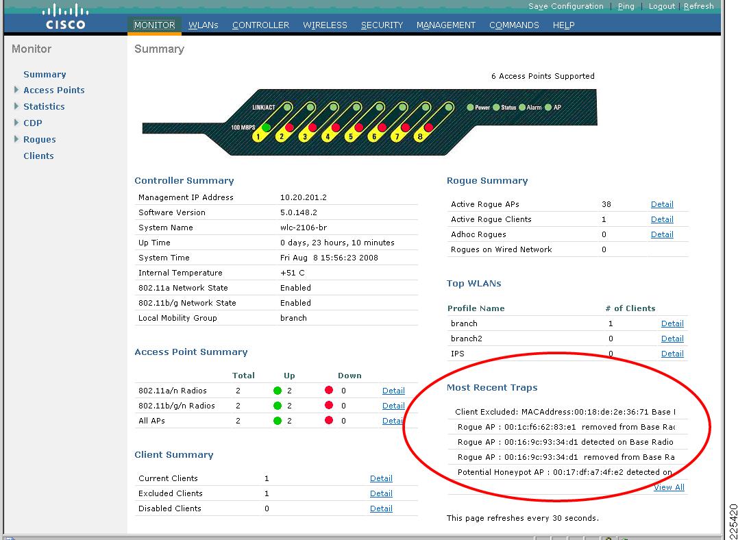
WLC Summary Screen
The WLC summary screen includes a Most Recent Traps section where a WLAN client block event appears as a client exclusion event. On the WLC, go to Monitor -> Summary. (See Figure 8-30).
Figure 8-30 WLC Summary Screen Showing a WLAN Client Block Event
WLC SNMP Trap Logs
The WLC SNMP trap logs include all SNMP traps generated by a WLC. An SNMP trap generated upon a WLAN client block event appears in the log as a client exclusion event. To view the SNMP trap log on a WLC, go to Management -> SNMP -> Trap Logs. (See Figure 8-31.)
Figure 8-31 WLAN Client Exclusion Trap Generated as a Result of a WLAN Client Block
Note the following:
•
•
IPS Events Related to Host Block Events
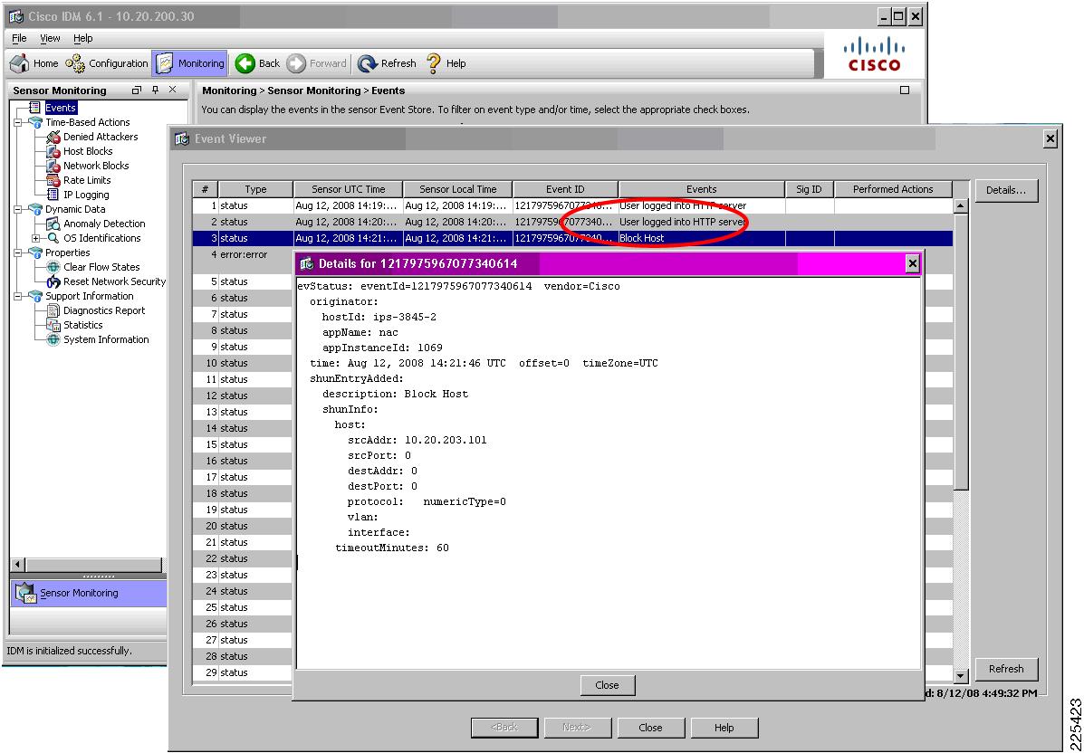
The events generated by a Cisco IPS when a host block is activated can be viewed on IDM.
On IDM, go to Monitoring -> Events. Enable Show status events, define a short timeframe for Show past events (shown in Figure 8-32 for 3 minutes) and select View.
Figure 8-32 Viewing Host Block Events on the IDM
The IDM Event Viewer is subsequently displayed. In the IDM Event Viewer screen, a Block Host event is generated for each host block activated. Double-click on an event to see the details, including the IP address that was blocked. (See Figure 8-33.)
Figure 8-33 Block Host Event on the IDM
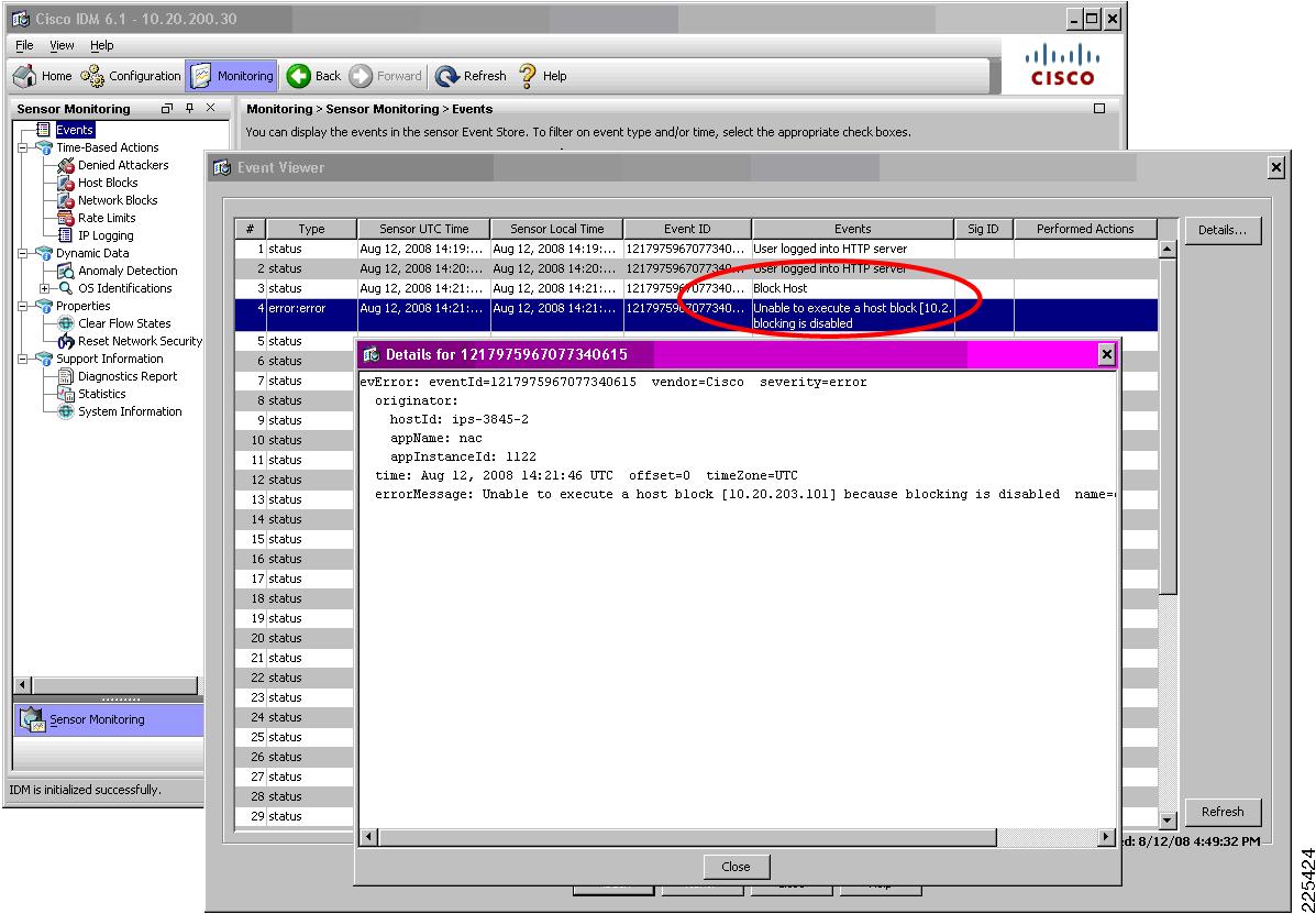
Note
This error message simply indicates that the IPS was not able push the host block policy out to a device. This is normal operation for the WLC-IPS collaboration, because the WLC pulls the active host block list from the IPS rather than the IPS actively pushing the host block out. The error is based on the push nature of the Attack Response Controller (ARC) feature, which expects blocking to be enabled and configured in order for a host block to be enforced. For more information on the ARC feature, refer to the IPS documentation (see Cisco IPS).Figure 8-34 Host Block Error Event on the IDM
WLC CLI Reporting of WLAN Client Block Events
The WLC CLI can be used to view an active host block list being received from the IPS and the shun list being updated.
To enable debugging for these events, perform the following steps:
Step 1
Step 2
debug wps cids enableDebugs automatically appear on the screen as soon as an event occurs.
The following is a sample of a WLC to Cisco IPS query for the shun list, which in this instance includes a new host block for IP address 10.20.203.101:
Tue Aug 12 14:21:43 2008: cidsProcessSdeeQuery: ip=10.20.200.30,port=443 state=1
interval=60
Tue Aug 12 14:21:43 2008: cidsQuerySend: https://10.20.200.30:443/cgi-bin/transaction-server?command=getShunEntryListTue Aug 12 14:21:43 2008: curlHandle is bbd422cTue Aug 12 14:21:43 2008: Perform on curlHandle bbd422c ...Tue Aug 12 14:21:43 2008: Response code is 0Tue Aug 12 14:21:43 2008: Add 10.20.203.101 from local sensor 10.20.200.30 to shun-listTue Aug 12 14:21:43 2008: xmlDoc buffer freedTue Aug 12 14:21:43 2008: Parser cleanedStep 3
debug wps cids disableIPS CLI Reporting of WLAN Client Block Events
The events generated on the IPS CLI when a host block is passed to a WLC can be seen by performing the following steps:
Step 1
Step 2
ips-3845-2# show events past 0:03 | include blockThe following is a sample of a host block being activated on a Cisco IPS and retrieval:
evStatus: eventId=1217975967077340614 vendor=Ciscooriginator:hostId: ips-3845-2appName: nacappInstanceId: 1069time: 2008/08/12 14:21:46 2008/08/12 14:21:46 UTCshunEntryAdded:description: Block HostshunInfo:host:srcAddr: 10.20.203.101srcPort: 0destAddr: 0destPort: 0protocol: numericType=0vlan:interface:timeoutMinutes: 60
Note
This error message simply indicates that the IPS was not able push the host block policy out to a device. This is normal operation for the WLC-IPS collaboration, because the WLC pulls the active host block list from the IPS rather than the IPS actively pushing the host block out. The error is based on the push nature of the Attack Response Controller (ARC) feature, which expects blocking to be enabled and configured in order for a host block to be enforced. For more information on the ARC feature, refer to the IPS documentation (see Cisco IPS).evError: eventId=1217975967077340615 severity=error vendor=Ciscooriginator:hostId: ips-3845-2appName: nacappInstanceId: 1122time: 2008/08/12 14:21:46 2008/08/12 14:21:46 UTCerrorMessage: name=errSystemError Unable to execute a host block [10.20.203.101] because blocking is disabledViewing Excluded Clients
All client exclusions currently in place on a WLC, along with the reason for the exclusion, can be seen on a WLC in the "Excluded Clients" list. This can be viewed by going to Monitor -> Summary and clicking on Detail next to "Excluded Clients" under the Client Summary section. (See Figure 8-35.)
Figure 8-35 WLC Monitor Summary screen with Excluded Clients Detail Link
The Excluded Clients list is subsequently displayed. (See Figure 8-36.)
Figure 8-36 Excluded Clients List
Note the following:
•
•
•
•
•
WCS Cross-WLC Monitoring of WLAN Client Block Events
If WCS cross-WLC monitoring is enabled, the WCS can be consulted for a consolidated view of currently shunned clients and currently excluded clients, as well as historical security events and statistics. For details on enabling WCS cross-WLC monitoring of WLAN events, refer to Enabling WCS Cross-WLC Monitoring of WLAN Events.
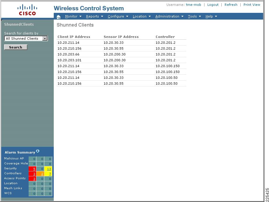
Consolidated Shunned Clients List
WCS provides a consolidated shunned clients list, showing all active host blocks passed to all WLCs.
On WCS, go to Monitor -> Security -> Shunned Clients. Select a search option from the drop-down list, which enables a listing of blocked clients to be generated based on all, per-controller, or per-client IP address. (See Figure 8-34.)
Figure 8-37 WCS Cross-WLC View of Shunned Clients
Note the following:
•
•
•
•
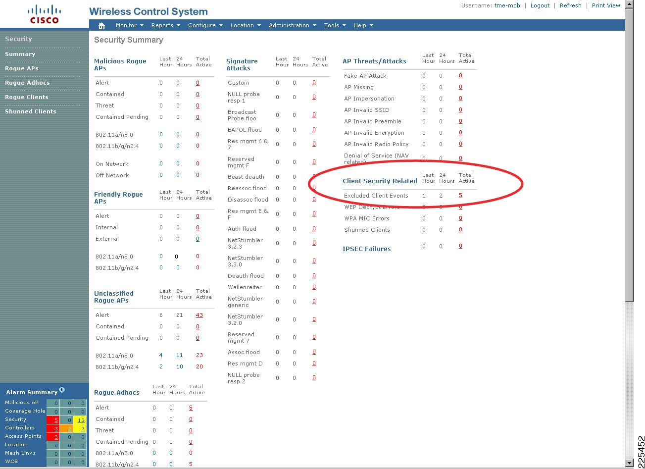
Consolidated Excluded Client Events List
WCS provides a consolidated list of active client exclusions across all WLCs.
On WCS, go to Monitor -> Security -> Summary and click on the Total Active field that corresponds to Excluded Client Events. (See Figure 8-38.)
Figure 8-38 Sample WCS Security Summary Screen
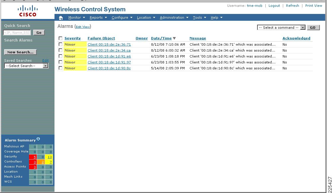
The active client exclusions across all WLCs is subsequently displayed. (See Figure 8-39.)
Figure 8-39 Sample WCS Active Excluded Client Events Screen
Note the following:
•
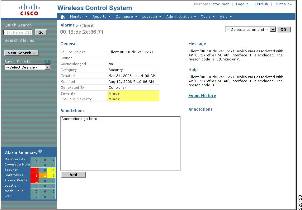
More detailed information on any particular exclusion event can be viewed by clicking the client. (See Figure 8-40.)
Figure 8-40 WCS Detailed Client Exclusion Event Screen
General Guidelines for Cisco Wireless and Network IDS/IPS Integration
General guidelines for deploying wireless and network IDS/IPS include the following:
•
•
•
•
•
Additional Information
Cisco WLC and IPS Collaboration Operational Details
General information related to Cisco WLC and IPS integration that should be considered from an operational perspective includes the following:
•
•
•
•
•
•
•
•
•
•
•
•
•
•
Cisco IPS Deployment Modes
One of the key design choices when deploying this functionality is between IDS or IPS mode:
•
Promiscuous mode passive monitoring, whereby traffic is passed to an IDS for analysis through a monitoring port. Upon detection of anomalous behavior, management systems are informed of an event. Operational staff subsequently decide what action, if any, to take in response to the incident.
•
Inline mode active monitoring, whereby an IPS is in the data path. The detection capabilities are the same as for an IDS, but an inline configuration provides operational staff with the option to filter malicious traffic on the IPS device itself.
Note
An IPS sensor can generally only be configured to operate in either IDS or IPS mode. A design may, however, require both modes to be deployed; for instance, to provide passive monitoring on some flows and active monitoring on other flows, perhaps on a per-VLAN basis. To enable this scenario to be achieved, a design may use the following:
•
•
See the product pages for detailed information on the products, platforms and features, as well as deployment options and considerations. For details, refer to Reference Documents.
Cisco IPS Block versus Deny Actions
A Cisco IPS block action, although activated on the IPS, is enforced on a collaborating device. The Cisco IPS relies on this collaborating device to enforce threat mitigation through a localized technique. On a Cisco Unified Wireless Network, the collaborating device in this scenario is the Cisco WLC and the local threat mitigation technique is client exclusion.
In contrast, a Cisco IPS deny action is both created and enforced on the IPS. The IPS itself filters the traffic to mitigate the attack. A deny action does not trigger a WLAN client block on a WLC.
If desired, activation of both a block action and a deny action can be used to enforce threat mitigation both directly on the IPS and through collaboration with another network device, such as a Cisco WLC.
Note
Cisco IPS and WLC Integration Dependencies
Collaboration between a Cisco IPS and WLC is dependent upon the software and hardware platforms identified in Table 8-3.
Note that Cisco IOS IPS for routing platforms, including the Cisco Integrated Services Routers (ISRs), does not currently support integration with a Cisco WLC for threat mitigation.
Test Bed Hardware and Software
Integration testing was performed and verified between all the IPS and WLC platforms and software releases shown in Table 8-4.
•
•
•
Reference Documents
Cisco IPS
•
•
http://www.cisco.com/en/US/products/hw/vpndevc/ps4077/prod_configuration_examples_list.html
•
•
Cisco Security Portfolio
•
http://www.cisco.com/en/US/products/hw/vpndevc/index.html
Cisco Unified Wireless
•
http://www.cisco.com/en/US/netsol/ns340/ns394/ns348/ns386/networking_solutions_package.html
•
http://www.cisco.com/en/US/products/hw/wireless/index.html
•
http://www.cisco.com/en/US/tech/tk722/tk809/technologies_configuration_example09186a00807360fc.shtml
General Network Security
•
http://www.cisco.com/en/US/docs/solutions/Enterprise/Security/Baseline_Security/securebasebook.html