-
Wireless and Network Security Integration Solution Design Guide
-
Preface
-
Solution Overview
-
Solution Architecture
-
802.11 Security Summary
-
Cisco Unified Wireless Network Architecture— Base Security Features
-
Wireless NAC Appliance Integration
-
Secure Wireless Firewall Integration
-
CSA for WLAN Security
-
Cisco Wireless and Network IDS/IPS Integration
-
CS-MARS Integration for Cisco Unified Wireless
-
Glossary
-
Table Of Contents
Secure Wireless Firewall Integration
Alternatives to an Access Edge Firewall
Protection against Viruses and Worms
Applying Guest Access Policies
FWSM and ASA Modes of Operation
ASA Admin Context Configuration
Service Groups and Windows Domain Authentication
WLAN Client Roaming and Firewall State
Architectural Impact of Symmetric Layer 3
Configuration Changes for Symmetric Layer 3 Roaming
Layer 3 Roaming is Not Mobile IP
Branch WLC Deployments and IOS Firewall
General IOS Firewall Inspect Statement
Secure Wireless Firewall Integration
The modern enterprise has many different types of employees needing network access, and many drivers to provide differentiated access to the network. The Cisco Unified Wireless solution addresses this need directly through the implementation of multiple service set identifiers (SSIDs), per-user or identity-based virtual LANs (VLANs), per-user or identity-based quality of service (QoS) assignment, guest access services, and WLC filtering features. The integration of other Cisco products into the Cisco Unified Wireless Solution can provide additional access customization if required, such as the following:
•
In cases where stateful packet inspection is required, a firewall may be used in addition to the filters available on the Wireless LAN Controller (WLC) or upstream router access control lists (ACLs).
•
•
Role of the Firewall
Firewalls have long provided the first line of defense in network security infrastructures. They accomplish this by comparing corporate policies about user network access rights with the connection information surrounding each access attempt and connection. User policies and connection information must match, or the firewall does not grant access to network resources. This helps prevent break-ins.
In recent years, a growing best practice has been to deploy firewalls not only at the traditional network perimeter, where the private corporate network meets the public Internet, but also throughout the enterprise network in key internal locations, as well as at the WAN edge of branch office networks. This distributed firewall strategy helps protect against internal threats, which have historically accounted for a large percentage of cyber losses, according to annual studies conducted by the Computer Security Institute (CSI).
The rise of internal threats has come about by the emergence of new network perimeters that have formed inside the corporate LAN. Examples of these perimeters, or trust boundaries, are between switches and back-end servers, between different departments, and where a wireless LAN meets the wired network. The firewall prevents access breaches at these key network junctures, ensuring, for example, that sales representatives are unable to gain access to the commission tracking finance system.
Placing firewalls in multiple network segments also helps organizations comply with the latest corporate and industry governance mandates. The Sarbanes-Oxley Act, the Gramm-Leach-Bliley (GLB) Act, the Health Insurance Portability and Accountability Act (HIPAA), and the Payment Card Industry (PCI) Data Security Standard contain requirements about information security auditing and tracking.
In addition to being deployed in more locations within an enterprise, firewalls have grown more sophisticated since their mainstream introduction approximately a decade ago. They have gained additional preventive capabilities, such as application and protocol inspection, which help avoid exploits of operating system and application vulnerabilities.
Firewalls have been enhanced with extra preventive features such as application inspection capabilities, which provides the ability to examine, identify, and verify application types and to treat traffic according to detailed policies based on variables beyond simply connection information. This helps identify, and thus block, traffic and users that unlawfully try to gain access to the network using an open port.
For example, HTTP is used to transport web data and services. It currently comprises approximately 75 percent of network traffic and natively uses application port 80. In most firewalls, port 80 is left open at all times, so any traffic destined for port 80 is admitted. Hackers, worms, and viruses can use this pinhole to attack a web application and to possibly gain access to sensitive data.
To protect against this, application filtering involves deep packet inspection to determine exactly what HTTP application traffic is attempting to enter the network. There are many HTTP applications that organizations want to let onto their networks; however, there might be some that they prefer to block. The application firewall also uses deep packet inspection to determine whether the application protocol (in this case, HTTP) is behaving in an irregular manner.
For example, policies can be set to identify and block overly long HTTP headers or those containing binary data that suggest a possible attack. Administrators can also set a policy to limit server requests to a certain number per minute to avoid denial of service (DoS) attacks.
A firewall provides greater protection than simple ACLs because it is able to protect against attacks using IP fragments, Session layer, and application weaknesses. The Cisco stateful firewall technology goes beyond simple firewall protection by analyzing the higher layer behavior for selected protocols to ensure that an attacker is not able to attack at that layer. Addresses and protocols to be used must be stable and well-defined to be effective. Otherwise, the firewall policy is too general to be effective, or requires too many adds, moves, and changes to be effective or secure. This is why firewalls are still generally deployed at the enterprise Internet edge where the enterprise communication is well-defined, and not within the enterprise network itself, where the protocols and peer relationships are less well-defined.
Although a WLAN client connection is often better secured than a wired client connection in enterprise WLAN deployments, the following are some reasons why enterprise WLAN deployments may include firewalls:
•
•
•
Alternatives to an Access Edge Firewall
For many enterprises, network segmentation is one of their security goals for WLANs. If segmentation is required, ACLs provide a flexible method of achieving their segmentation goals, and may make their security investment in other areas.
Note
Because of the nature of most enterprise networks, it is very difficult to determine which network addresses (destinations) and protocols should be accessible to one client rather than another. Therefore, a firewall is more likely to be placed near application servers where the protocols and addresses for applications and administration are much more clearly defined, rather than at the access edge. For guidance on data center firewall deployments, see the following URL:
http://www.cisco.com/application/pdf/en/us/guest/netsol/ns376/c649/ccmigration_09186a008078de90.pdf.
Protection against Viruses and Worms
If there is a concern regarding possible virus or worm attacks, a firewall can provide only limited protection because the firewall typically cannot know the application weakness exploited by many attacks, and can protect only against protocol attacks. The most common strategy when addressing client viruses and worms can best be described as one of "trust, but verify and monitor". In this strategy, client devices are given access to the network, but the status of their associated operating systems and protection software is verified before access is granted, and the behavior of the client is monitored to identify suspicious behavior.
As an example, assume that an enterprise WLAN client has authenticated to gain access to the network, and that their connection to the network is protected against attack. The task is then to ensure that the WLAN client is not hosting a virus or worm, and that the WLAN client is not behaving inappropriately. These tasks can be performed though Network Admission Control (NAC) and Intrusion Prevention System (IPS), including host-based IPS systems such as CSA, which ensures that the current versions of anti-virus software are installed and the current patch level is maintained.
The Cisco NAC Appliance, in addition to performing authentication and policy enforcement, performs a posture assessment of client software to ensure that they are running the correct levels of software and patches, and guides clients to remediation if required.
IPS monitors client behavior, and can react to suspicious behavior by sending alarms and alerts, blocking access to services, or blocking client network access.
Applying Guest Access Policies
Applying a firewall at the access edge to control guest access provides limited utility because it primarily acts as a simple access list, blocking access to internal IP addresses. It does not address the transport of guest client traffic across the enterprise network to the Internet edge. A better solution is to implement a dedicated guest access WLAN/service, which is natively supported in the Cisco Unified Wireless solution.
For more details, refer to Chapter 12 of the Enterprise Mobility Design Guide at the following URL: http://www.cisco.com/en/US/docs/solutions/Enterprise/Mobility/emob30dg/emob30dg-Book.html.
ACLs and firewalls are still a desirable component in a guest access deployment, with ACLs in the access layer and firewalling at the Internet edge.
Firewall Integration
Many WLC and firewall combinations are possible with the range of Cisco WLCs and firewall products. This chapter focuses on three different examples of Firewall Integration:
•
•
•
However, the design principles and configuration examples shown in this chapter are applicable to other product configurations.
For more information on Cisco security products, see the following URL: http://www.cisco.com/en/US/products/hw/vpndevc/index.html.
The FWSM software used in this guide is version 3.1(4), and ADSM version 5.0(2)F.
FWSM, ASA, and IOS Firewall
The Cisco FWSM and ASA provides an industry-leading connections per second, throughput, and concurrent connections per module/Appliance. Multiple FWSMs or ASA s can be clustered using static VLAN configurations or Cisco IOS Software policy-based routing for directing traffic to these FWSMs or ASAs. Up to four FWSMs can be deployed in the same chassis for a total of 20 Gbps throughput. Differnent ASA appliances are available to meet different customer capacity requirements, these appliances have a range of firewall throughputs from 150Mpbs to 5Gbps .
A single FWSM can support up to 1000 virtual interfaces (256 per context), and a single chassis can scale up to a maximum of 4000 VLANs. In addition, two Cisco Application Control Engines (ACEs) can be used within the Cisco Catalyst 6500 Series chassis to load balance between three FWSMs for more than 15 Gbps of firewall throughput. Full firewall protection is applied across the switch backplane, giving the lowest latency figures possible (30 ms for small frames). The Cisco FWSM is based on high-speed network processors that provide high performance but retain the flexibility of general-purpose CPUs.
For more information on the FWSM, see the following URL: http://www.cisco.com/en/US/products/hw/switches/ps708/products_module_configuration_guide_book09186a0080579a1e.html
For more information on the range of ASA models available see the following URL: http://www.cisco.com/en/US/partner/products/ps6120/prod_models_comparison.html
Cisco IOS Firewall is on IOS intergrated solution that helps ensure your network's availability and the security of your company's resources by protecting the network infrastructure against network- and application-layer attacks, viruses, and worms. It protects unified communications by guarding Session Initiation Protocol (SIP) endpoints and call-control resources. Cisco IOS Firewall is a stateful firewall solution, certified by Common Criteria (EAL4). Cisco IOS Firewall is suitable for branch offices, small to medium business environments, or managed services, Cisco IOS Firewall effectively controls application traffic on the network. A fundamental part of the Cisco Integrated Threat Control framework, it works with other Cisco IOS security features, including Cisco IOS Intrusion Prevention System (IPS), IOS Content Filtering, and IOS Network Address Translation (NAT), to create a completely integrated branch-office perimeter security solution.
Before examining some sample configurations in this document, the characteristics of the firewalls solutions need to be considered. The architecture and and firewall configuration options in the both the FWSM and ASA are very similar and may discussed together, whereas the IOS Firewall architecture and configuration options are different and they will be discussed in a later separate section of this chapter.
FWSM and ASA Modes of Operation
The following FWSM and ASA modes of operation need to be considered:
•
•
Routed versus Transparent
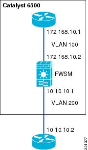
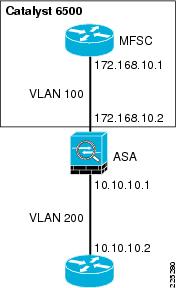
The firewall can operate in either routed or transparent mode. In routed mode, the firewall acts as a Layer 3 interface for traffic and the route configuration to control traffic flow as well as the policy that is configured on the firewall (see Figure 6-1 and Figure 6-2).
Figure 6-1 FWSM Routed Mode
Figure 6-2 ASA Routed Mode
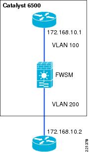
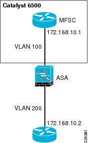
In transparent mode, the firewall acts as a "bump-in-the-wire", applying policy at Layer 2. The inside and outside of the firewall are on the same subnet (see Figure 6-3 and Figure 6-4).
Figure 6-3 FWSM Transparent Mode
Figure 6-4 ASA Transparent Mode
The examples in this chapter use the router in transparent mode because it allows the firewall functionality to be inserted without changing the WLAN addressing scheme or additions to the routing scheme. For more information about firewall modes, refer to the following URL: http://www.cisco.com/en/US/docs/security/asa/asa80/configuration/guide/intro.html#wp1047294
Single or Multiple Context
A FWSM or ASA can be partitioned into multiple virtual devices, known as security contexts. Each context has its own security policy, interfaces, and administrators. Multiple contexts are similar to having multiple standalone devices. Most features are supported in multiple context mode, including routing tables, firewall features, and management. Some features are not supported, including dynamic routing protocols.
In multiple context mode, the FWSM or ASA includes a configuration for each context that identifies the security policy, interfaces, and almost all the options you can configure on a standalone device.
The system administrator adds and manages contexts by configuring them in the system configuration, which, like a single mode configuration, is the startup configuration. The system configuration identifies basic settings for the FWSM or ASA . The system configuration does not include any network interfaces or network settings for itself. When the system needs to access network resources (such as downloading the configuration from a server), it uses one of the contexts that has been designated as the "admin" context.
Multiple virtual device configuration has a number of advantages if dynamic routing and multicast are not required. In the example used in this guide, the primary advantages are as follows:
•
•
•
For more information on the differences in single and multiple context features, refer to the following URL:
http://www.cisco.com/en/US/docs/security/fwsm/fwsm31/configuration/guide/fwsm_cfg.html
Basic Topology
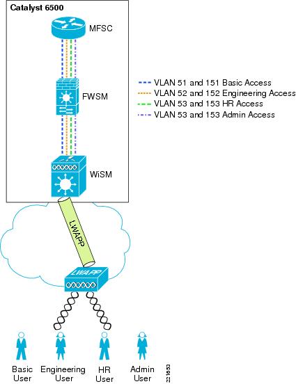
Figure 6-5 and Figure 6-6 show the basic module configuration used in the sample firewall/WLAN topology. The FWSM or ASA is configured for transparent mode to firewall between the WiSM client VLANs and the routing engine of the 6500 Multi-Feature Switch Card (MFSC), so that WLAN client traffic must traverse the FWSM or ASA to reach its subnet default gateway.
In the example shown, there are two VLANs defined for each WLAN: a 15x VLAN from the WiSM to the FWSM or ASA and a 5x VLAN between the FWSM and MFSC. These VLANs force the WLAN client traffic through the FWSM on its way to its default gateway.
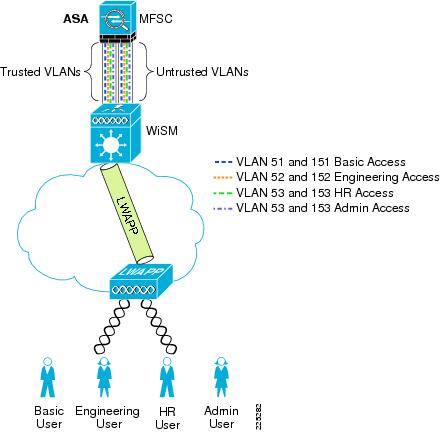
The primary difference between the ASA and FWSM configuration is simply that the ASA does not connect directly to the 6500 switch backplane, trusted and untrusted VLANs must be assigned to switch ports, and these ports cabled to the ASA.
Figure 6-5 Basic FWSM Configuration
Figure 6-6 Basic ASA Configuration
Example Scenario
Department Partitioning
In this scenario, the enterprise wishes to control access to applications, depending on the department membership. This example describes the following four access level scenarios:
1.
–
–
2.
–
–
3.
–
–
4.
–
Note
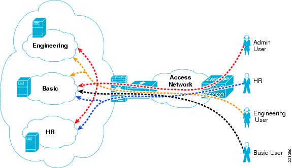
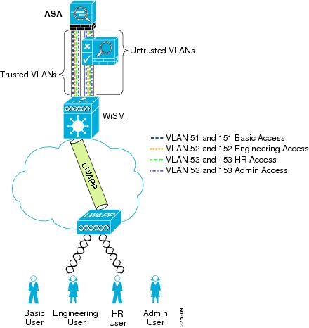
One common WLAN SSID is used, and VLAN assignment is based on user ID and group membership. This method is superior to using different SSIDs for each group, because changing client group membership or adding or reducing groups does not require changes to the client. Figure 6-7 shows the concept where various users share the WLAN infrastructure, but are allowed access to network addresses/resources and protocols based only on their roles.
Figure 6-7 User Network Traffic Access
WLAN user access involves the following steps:
1.
2.
3.
4.
5.
ACS RADIUS Configuration
The ACS server uses the RADIUS protocol to pass additional information to the RADIUS clients, based on the group membership of the authenticated user. Group membership in the ACS can be based either on local configuration within the ACS server, or based on membership criteria maintained in an external authentication database for the user. For simplicity, this example uses local group configuration information in ACS for user group membership for the following user types:
•
•
•
•
The ACS groups assigned are as follows:
•
•
•
•
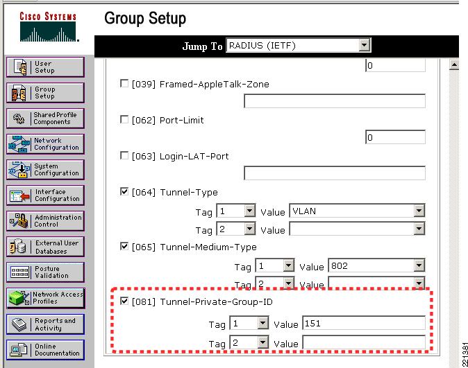
Figure 6-8 shows an example of the relevant group settings for this configuration; for example, the VLAN assignment for each user. These assignments are part of the group IETF RADIUS options. The example shown in Figure 6-8 is for the group BasicUser. The Tunnel Type, and the Tunnel Medium Type define that VLAN information is being passed, and the the Tunnel-Private-Group-ID passes the VLAN number. The VLAN assignments for groups BasicUser, EngUser, HRUser, and AdminUser are 151, 152, 153, and 154, respectively.
Note
Figure 6-8 Group VLAN Setting
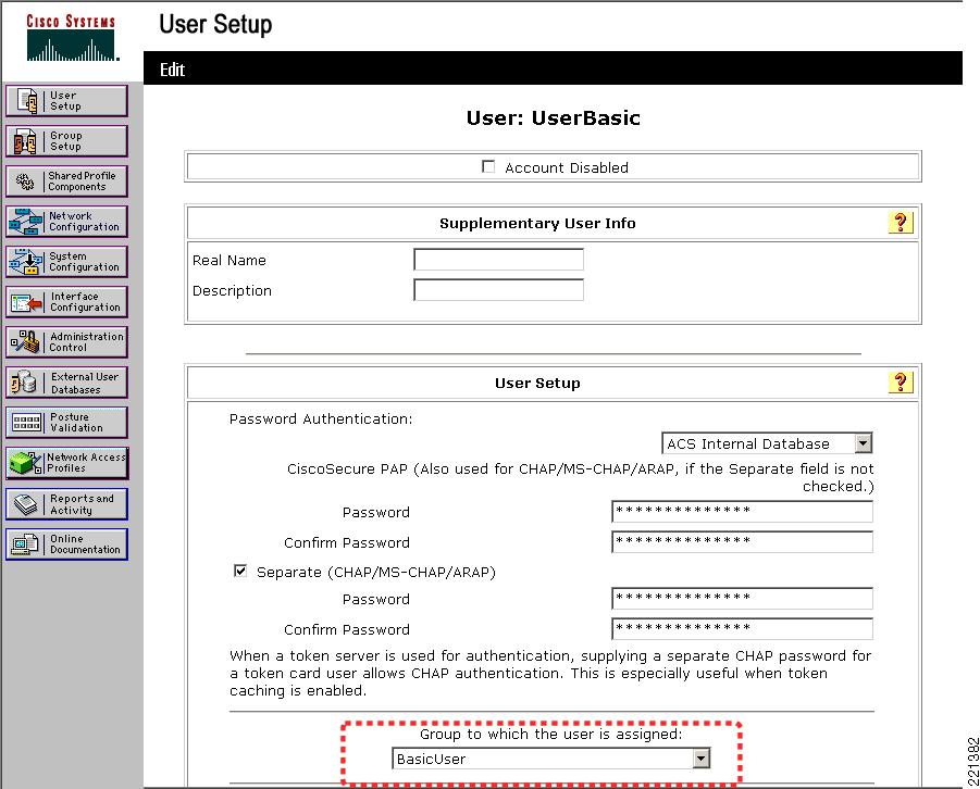
Figure 6-9 shows an example of the user-to-group mapping done through the ACS, where the user UserBasic is mapped to the BasicUser group.
Figure 6-9 User Group Setting
WLC Configuration
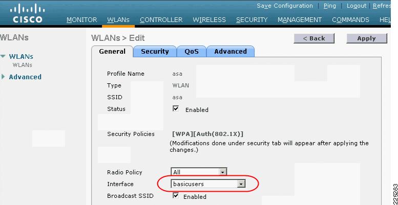
The primary WLC configuration details in this example are the WLAN configuration and the WLC interface configuration. The sample WLAN configuration is shown in Figure 6-10. In addition to ensuring that the WLAN security is based on 802.1X authentication so that the VLAN mapping information can be passed, the most important configuration detail is the WLC interface to which the WLAN maps.
Figure 6-10 WLC WLAN Configuration
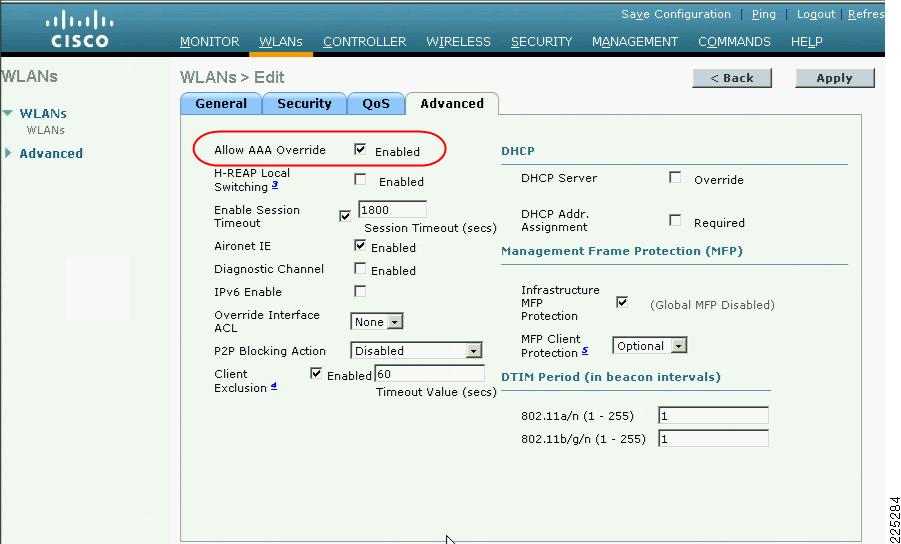
In this case, the mapping is to the basicusers interface, which offers the lowest level of access through the FWSM. Note that if the VLAN information sent in the RADIUS accept packet does not match with a corresponding dynamic interface on the WLC, the WLAN client is connected to the (default) interface specified in the WLAN configuration. To allow the AAA server to change the WLAN VLAN mapping, AAA override must be configured for that WLAN, as shown in Figure 6-11.
Figure 6-11 AAA Override
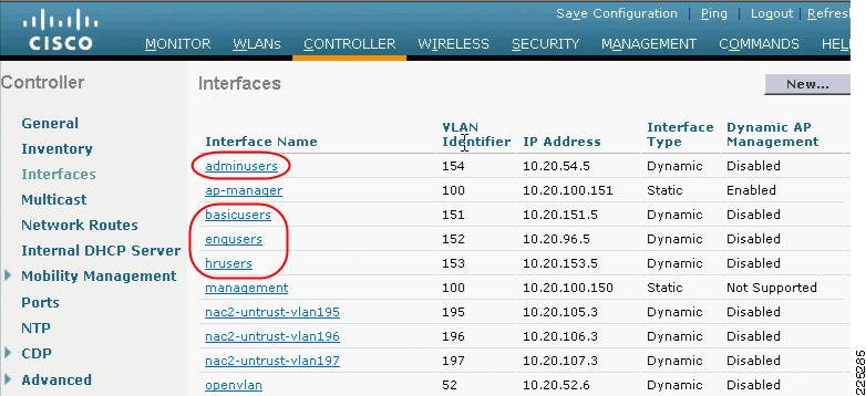
Figure 6-12 shows the WLC interface configuration with each of the possible FWSM VLANs defined as dynamic interfaces. However, note that basicuser is selected as the default interface for the WLAN configuration in Figure 6-10. Interfaces adminusers, engusers, and hrusers are not associated with a WLAN and are used only when VLAN attributes are passed on as part of a successful 802.1X/EAP authentication.
Figure 6-12 WLC Interface Configuration
FWSM or ASA Configuration
The syntax for the firewall configuration of the ASA and FWSM are fundamentally the same when implementing firewall policy, and the main differences are the connection to the 6500 the ASA uses physical interfaces connected to switch modules rather than VLAN interfaces used by the FWSM connect to the 6500 backplane. Where there are difference in configuration these will be noted, and when the configuration is common this will also be noted. There is configuration on the 6500 is required before configuring the FWSM.
The following configuration example shows the 6500 VLAN configuration needed to support a FWSM or ASA deployment. VLAN 50 is used as the administration interface for the FWSM, VLANs 51-54 are the trusted VLANs for the various user groups, and VLANs 151-154 are the untrusted VLANs. Note that only VLANs 50-54 have interfaces configured with IP addresses.
VLANs 55 and 56 are used later in the design example where two FWSMs or ASAs are deployed in a high availability configuration.
VLANs 57 and VLAN 58 are defined for the separate administrative interfaces for the FWSM or ASA security contexts.
vlan 50name FWSM-admin!vlan 51name FWSM-Trusted-BasicGroup!vlan 52name FWSM-Trusted-EngGroup!vlan 53name FWSM-Trusted-HRGroup!vlan 54name FWSM-Trusted-AdminGroup!vlan 55name Failover-VLAN!vlan 56name State-VLAN!vlan 57name FWSM-EngineeringContext-admin!vlan 58name FWSM-StaffContext-admin!vlan 151name FWSM-Untrusted-BasicGroup!vlan 152name FWSM-Untrusted-EngGroup!vlan 153name FWSM-Untrusted-HRGroup!vlan 154name FWSM-Untrusted-AdminGroup!!interface Vlan50description FWSM Adminip address 10.20.50.2 255.255.255.0standby 121 ip 10.20.50.1standby 121 preempt!interface Vlan51description BasicUsersip address 10.20.51.2 255.255.255.0ip helper-address 10.20.30.11standby 121 ip 10.20.51.1standby 121 preempt!interface Vlan52description EngUsersip address 10.20.52.2 255.255.255.0ip helper-address 10.20.30.11standby 121 ip 10.20.52.1!interface Vlan53description HRUsersip address 10.20.53.2 255.255.255.0ip helper-address 10.20.30.11standby 121 ip 10.20.53.1standby 121 preempt!interface Vlan54description AdminUsersip address 10.20.54.2 255.255.255.0ip helper-address 10.20.30.11standby 121 ip 10.20.54.1standby 121 preempt!interface Vlan57description EngineeringContext Adminip address 10.20.57.2 255.255.255.0standby 121 ip 10.20.57.1standby 121 preempt!interface Vlan58description StaffContext Adminip address 10.20.58.2 255.255.255.0standby 121 ip 10.20.58.1standby 121 preemptThe following configuration example shows the 6500 configuration commands that identify interfaces to be used by the FWSM. Note that firewall multiple-vlan-interfaces is required because of the number of routable interfaces mapped to the FWSM.
Note
firewall multiple-vlan-interfacesfirewall module 2 vlan-group 50firewall vlan-group 50 50-58,150-155FWSM Configuration
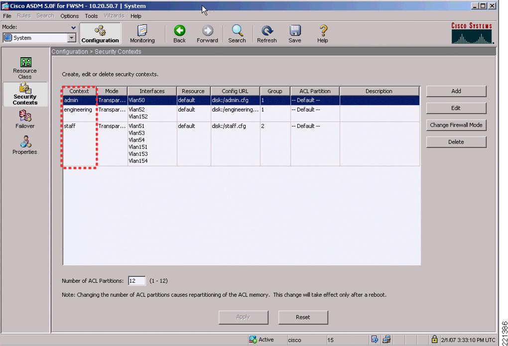
Figure 6-13 shows the Cisco Adaptive Security Device Manager (ASDM) configuration screen for the FWSM (or ASA) that defines the various security contexts to the FWSM and specifies which VLANs are assigned to each context. In this example, the same operations group supports basic users, HR users, and Admin users; therefore, their VLAN pairs can be in the same context, called staff. The operational support of the engineering group is performed by a separate operations group, and their VLAN pairs are in a separate context, called engineering.
A separate admin context is also created for the administration of FWSM. This context has one VLAN connected to the trusted side of the network.
Note
Figure 6-13 ASDM FWSM Security Contexts
The following is an example of the system configuration. This is the information that is seen when using the session command from the 6500 to communicate to the FWSM. The important points to note in this configuration are the creation of the different contexts, assigning VLANs to the contexts, and naming the file that saves the context configuration.
To show and configure a particular context, the changeto context name syntax is used.
FWSM Version 3.1(6) <system>!resource acl-partition 12hostname FWSM-1domain-name srnd3.netconsole timeout 0admin-context admincontext adminallocate-interface Vlan50config-url disk:/admin.cfg!context engineeringallocate-interface Vlan152allocate-interface Vlan52allocate-interface Vlan57config-url disk:/engineering.cfg!context staffallocate-interface Vlan151allocate-interface Vlan153allocate-interface Vlan154allocate-interface Vlan51allocate-interface Vlan53allocate-interface Vlan54allocate-interface Vlan58config-url disk:/staff.cfgTo change to the admin context, the command syntax is changeto context admin. The following example shows the example configuration from the admin context that defines the VLAN used, its trust level, and the Bridge Group Virtual Interface (BVI) interface. Because the context is in transparent mode, it is acting as a bridge, and the BVI is used to make it IP addressable. Also note the http commands that enable support for the ASDM and define the IP addresses used by the ASDM client.
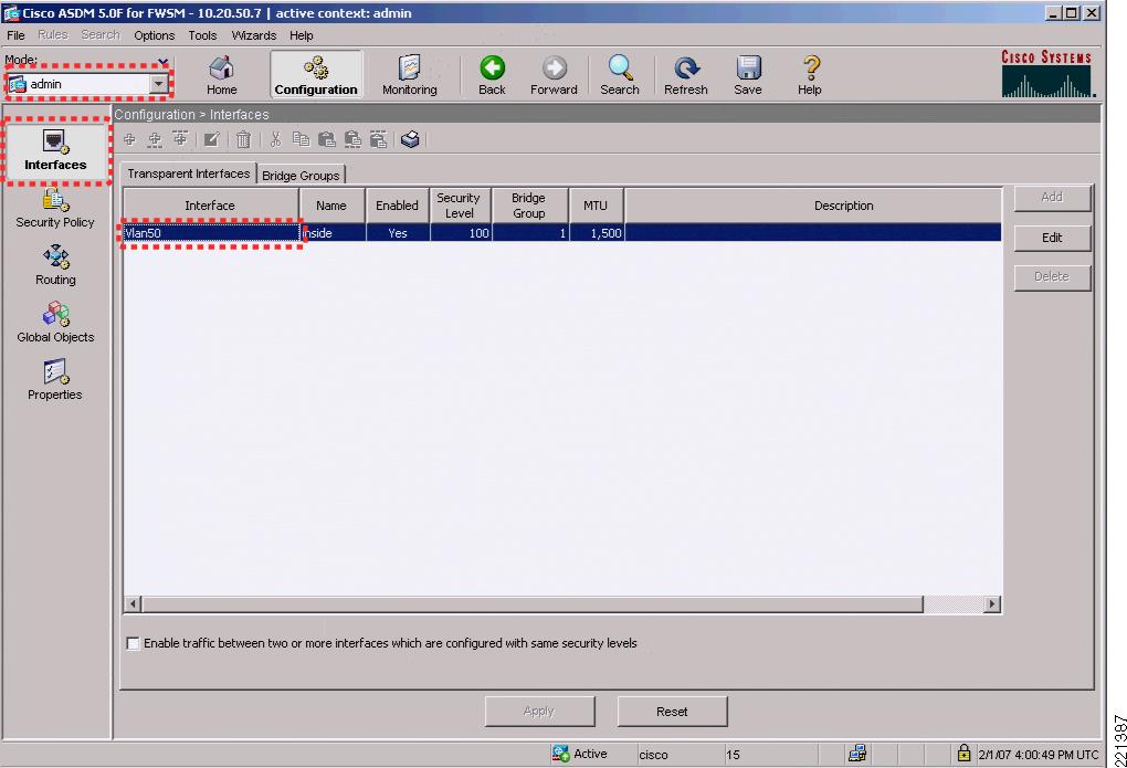
FWSM Version 3.1(4) <context>!firewall transparenthostname admininterface Vlan50nameif insidebridge-group 1security-level 100!interface BVI1ip address 10.20.50.7 255.255.255.0 standby 10.20.50.8...!route inside 0.0.0.0 0.0.0.0 10.20.50.1 1...http server enablehttp 10.20.30.0 255.255.255.0 insideFigure 6-14 shows the FWSM ASDM interface view of the admin context, where the VLANs and BVI interface are configured.
Figure 6-14 FWSM ASDM Admin Context Interfaces
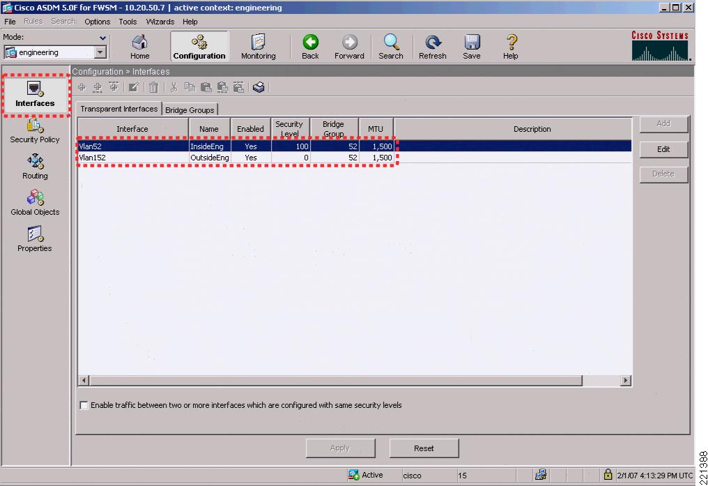
Figure 6-15 shows the FWSM engineering context where the VLANs and BVI information for the BVI interface are configured.
Figure 6-15 FWSM ASDM Engineering Interfaces
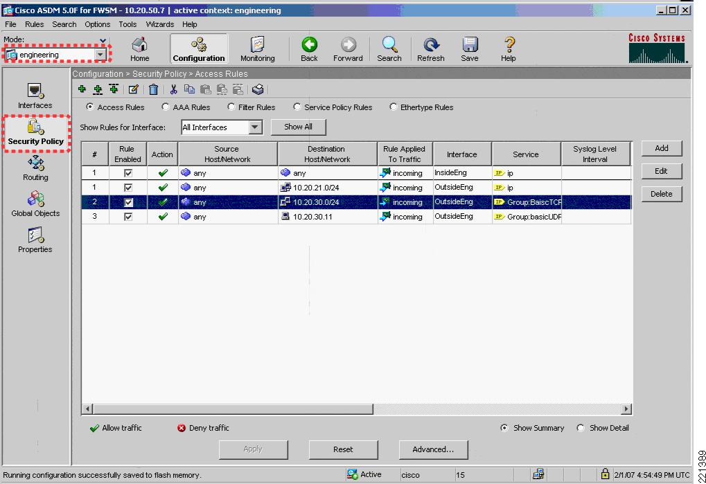
Figure 6-16 shows the ASDM engineering context Security Policy configuration page.
Figure 6-16 ASDM Engineering Security Policy
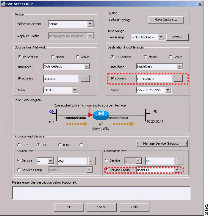
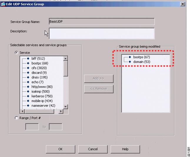
Figure 6-17 and Figure 6-18 show an example of the rules that can be applied in this policy page. In this example, the source interface OutsideEngineering is allowed through InsideEngineering to access host 10.20.30.11, using the UDP protocol group defined in service group BasicUDP. Figure 6-18 shows that the service group BasicUDP allows DHCP requests and DNS requests to the server. This is to allow basic DHCP and DNS addressing for the users.
Figure 6-17 FWSM ASDM Access Rules
Figure 6-18 FWSM UDP Service Group
The following configuration example shows the relevant CLI commands associated with this context, where additional security policies have also been added to allow access to other basic services on the 10.20.30.0/24 subnet and access to engineering services on the 10.20.21.0/24 subnet.
Note
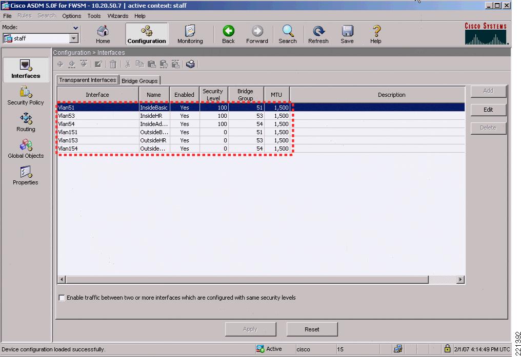
FWSM Version 3.1(4) <context>!firewall transparenthostname engineering!interface Vlan152nameif OutsideEngbridge-group 52security-level 0!interface Vlan52nameif InsideEngbridge-group 52security-level 100!interface Vlan57nameif EngineeringAdminbridge-group 57security-level 100!interface BVI57ip address 10.20.57.7 255.255.255.0 standby 10.20.57.8!object-group service basicUDP udpport-object eq bootpsport-object eq domainobject-group service BasicTCP tcpport-object eq wwwport-object eq imap4port-object eq httpsport-object eq pop3port-object eq smtpaccess-list OutsideEng_access_in remark access to engineering networkaccess-list OutsideEng_access_in extended permit ip any 10.20.21.0 255.255.255.0access-list OutsideEng_access_in extended permit tcp any 10.20.30.0 255.255.255.0 object-group BaiscTCPaccess-list OutsideEng_access_in extended permit udp any host 10.20.30.11 object-group basicUDPaccess-list InsideEng_access_in extended permit ip any anyaccess-list BPDU ethertype permit bpdumonitor-interface InsideEng...access-group BPDU in interface InsideEngaccess-group InsideEng_access_in in interface InsideEngaccess-group BPDU in interface OutsideEngaccess-group OutsideEng_access_in in interface OutsideEngroute EngineeringAdmin 0.0.0.0 0.0.0.0 10.20.57.1 1...http server enablehttp 10.20.30.0 255.255.255.0 EngineeringAdminFigure 6-19 shows the staff context where the VLANs and BVI information for the BVI interface are configured.
Figure 6-19 ASDM Staff Interfaces
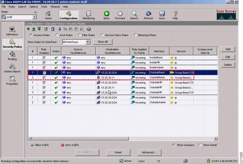
Figure 6-20 shows the ASDM staff context Security Policy configuration page.
Figure 6-20 ASDM Staff Security Policy
Following is the staff context configuration:
firewall transparenthostname staffdomain-name default.domain.invalidenable password 8Ry2YjIyt7RRXU24 encryptednames!interface Vlan151nameif OutsideBasicbridge-group 51security-level 0!interface Vlan153nameif OutsideHRbridge-group 53security-level 0!interface Vlan154nameif OutsideAdminbridge-group 54security-level 0!interface Vlan51nameif InsideBasicbridge-group 51security-level 100!interface Vlan53nameif InsideHRbridge-group 53security-level 100!interface Vlan54nameif InsideAdminbridge-group 54security-level 100!interface Vlan58nameif StaffAdminbridge-group 58security-level 100!interface BVI58ip address 10.20.58.7 255.255.255.0!...object-group service BasicUDP udpport-object eq bootpsport-object eq domainobject-group service BasicTCP tcpport-object eq wwwport-object eq httpsport-object eq imap4port-object eq pop3port-object eq smtpobject-group service HRTCP tcpport-object eq httpsaccess-list InsideBasic_access_in extended permit ip any anyaccess-list InsideHR_access_in extended permit ip any anyaccess-list InsideAdmin_access_in extended permit ip any anyaccess-list OutsideAdmin_access_in extended permit ip any 10.20.30.0 255.255.255.0access-list OutsideAdmin_access_in extended permit ip any 10.20.20.0 255.255.255.0access-list OutsideHR_access_in extended permit tcp any 10.20.20.0 255.255.255.0 object-group BasicTCPaccess-list OutsideHR_access_in extended permit udp any host 10.20.30.11 object-group BasicUDPaccess-list OutsideHR_access_in extended permit tcp any 10.20.30.0 255.255.255.0 object-group BasicTCPaccess-list OutsideBasic_access_in extended permit tcp any 10.20.30.0 255.255.255.0 object-group BasicTCPaccess-list OutsideBasic_access_in extended permit udp any host 10.20.30.11 object-group BasicUDPaccess-list BPDU ethertype permit bpdu...monitor-interface InsideBasicmonitor-interface InsideHRmonitor-interface InsideAdminno asdm history enablearp timeout 14400access-group BPDU in interface InsideBasicaccess-group InsideBasic_access_in in interface InsideBasicaccess-group BPDU in interface InsideHRaccess-group InsideHR_access_in in interface InsideHRaccess-group BPDU in interface InsideAdminaccess-group InsideAdmin_access_in in interface InsideAdminaccess-group BPDU in interface OutsideAdminaccess-group OutsideAdmin_access_in in interface OutsideAdminaccess-group BPDU in interface OutsideBasicaccess-group OutsideBasic_access_in in interface OutsideBasicaccess-group BPDU in interface OutsideHRaccess-group OutsideHR_access_in in interface OutsideHRroute StaffAdmin 0.0.0.0 0.0.0.0 10.20.58.1 1...http server enablehttp 10.20.30.0 255.255.255.0 StaffAdminASA Configuration
ASA and Security Contexts
The ASDM version used to configure the ASA was a different version to that used for the FWSM, due to a difference between between the FWSM software version and ASA software versions. There are versions of FWSM and ASA that can use the same ASDM interface, but these were not used in this design as we chose to use a version of FWSM from the Cisco Safe Harbor program.
Apart from the differences in ASDM interface, the primary difference is in the context configuration. The FWSM allows multiple interfaces per context, whereas the ASA allows two interfaces per context. This means that a security context needs to be created for each trusted untrusted VLAN pair. The additional security contexts are shown in Figure 6-21.
Figure 6-21 ASDM ASA Security Context Configuration
ASA CLI Context Configuration
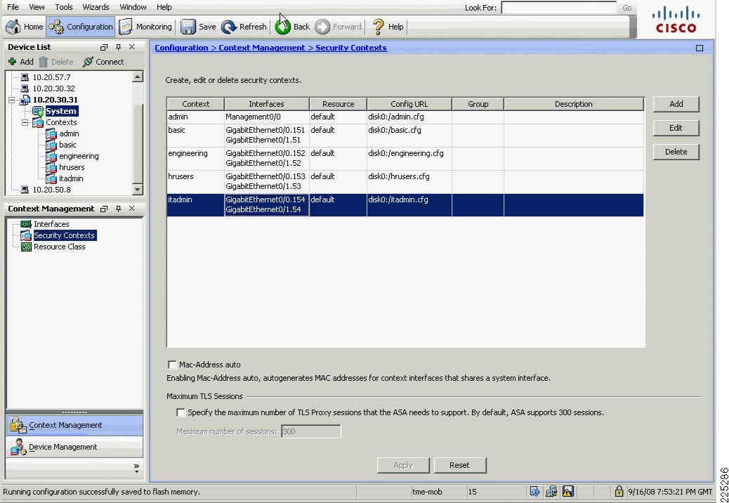
ASA Version 8.0(3) <system>!firewall transparenthostname asa-1!admin-context admincontext adminallocate-interface Management0/0config-url disk0:/admin.cfg!context engineeringallocate-interface GigabitEthernet0/0.152allocate-interface GigabitEthernet0/1.52config-url disk0:/engineering.cfg!context basicallocate-interface GigabitEthernet0/0.151allocate-interface GigabitEthernet0/1.51config-url disk0:/basic.cfg!context hrusersallocate-interface GigabitEthernet0/0.153allocate-interface GigabitEthernet0/1.53config-url disk0:/hrusers.cfg!context itadminallocate-interface GigabitEthernet0/0.154allocate-interface GigabitEthernet0/1.54config-url disk0:/itadmin.cfgFigure 6-22 shows the ASA ASDM interface view of the admin context, where the VLANs and BVI interface are configured.
Figure 6-22 ASA ASDM Admin Context Interfaces
The ASA has a dedicated management interface which was placed in the admin security context, the related configuration is shown below.
ASA Admin Context Configuration
firewall transparenthostname ciscoasaenable password 8oedxwIWpACbU1CP encryptednames!interface Management0/0nameif managementsecurity-level 100ip address 10.20.30.31 255.255.255.0management-only!...!route management 0.0.0.0 0.0.0.0 10.20.30.1 1http server enablehttp 10.20.30.0 255.255.255.0 management...Service Groups and Windows Domain Authentication
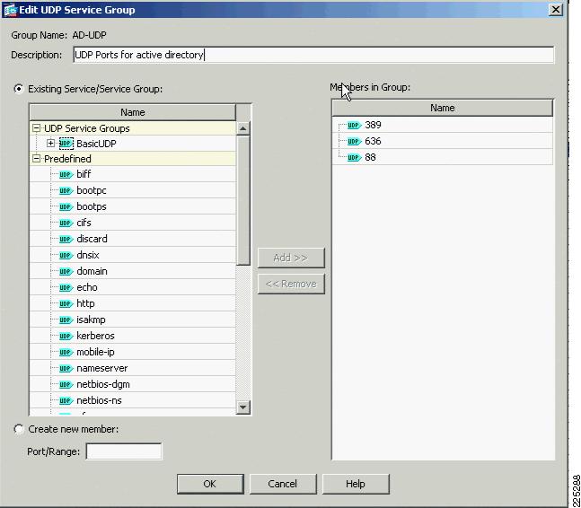
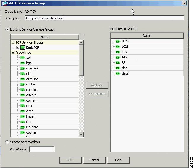
In the FWSM example service groups where created for basic UDP and TCP protocols that we wanted to support. The same type of service groups can be created on the ASA. In this ASA example we added two additional groups that were related to our testing. These groups AD-UDP (Figure 6-23) and AD-TCP (Figure 6-24) allow the passing of traffic required for a client to authenticate against Microsoft Active Directory. The requirement to allow this type of traffic is typical for many customers and was a requirement when we combined ASA and NAC appliance, as discussed later in this chapter.
Figure 6-23 AD-UDP Service Group
Figure 6-24 AD-TCP Service Group
Service Group Configuration
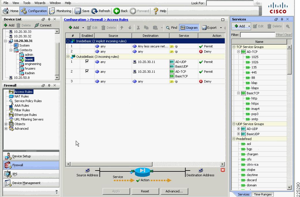
object-group service BasicUDP udpport-object eq bootpsport-object eq domainobject-group service BasicTCP tcpport-object eq wwwport-object eq imap4port-object eq httpsport-object eq pop3port-object eq smtpobject-group service AD-TCP tcpdescription TCP ports active directoryport-object eq 1025port-object eq 1026port-object eq 135port-object eq 445port-object eq 88port-object eq ldapport-object eq ldapsobject-group service AD-UDP udpdescription UDP Ports for active directoryport-object eq 389port-object eq 636port-object eq 88object-group service DM_INLINE_TCP_1 tcpgroup-object AD-TCPgroup-object BasicTCPobject-group service DM_INLINE_UDP_1 udpgroup-object AD-UDPgroup-object BasicUDPFigure 6-25 Basic Configuration
firewall transparenthostname basicenable password 8Ry2YjIyt7RRXU24 encryptednames!interface GigabitEthernet0/0.151nameif OutsideBasicsecurity-level 0!interface GigabitEthernet0/1.51nameif InsideBasicsecurity-level 100!...access-list OutsideBasic_access_in extended permit udp any host 10.20.30.11 object-group DM_INLINE_UDP_1access-list OutsideBasic_access_in extended permit tcp any host 10.20.30.11 object-group DM_INLINE_TCP_1pager lines 24...access-group OutsideBasic_access_in in interface OutsideBasicFigure 6-26 Engineering Configuration
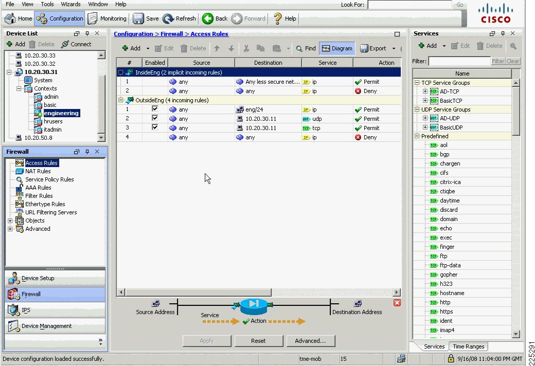
firewall transparenthostname engineering...!interface GigabitEthernet0/0.152nameif OutsideEngsecurity-level 0!interface GigabitEthernet0/1.52nameif InsideEngsecurity-level 100!...object-group service DM_INLINE_TCP_1 tcpgroup-object AD-TCPgroup-object BasicTCPobject-group service DM_INLINE_UDP_1 udpgroup-object AD-UDPgroup-object BasicUDPaccess-list InsideEng_access_in_1 extended permit ip any eng 255.255.255.0access-list OutsideEng_access_in_1 extended permit ip any eng 255.255.255.0access-list OutsideEng_access_in_1 extended permit udp any object-group DM_INLINE_UDP_1 host 10.20.30.11access-list OutsideEng_access_in_1 extended permit tcp any object-group DM_INLINE_TCP_1 host 10.20.30.11...access-group OutsideEng_access_in_1 in interface OutsideEngFigure 6-27 hrusers Context Configuration
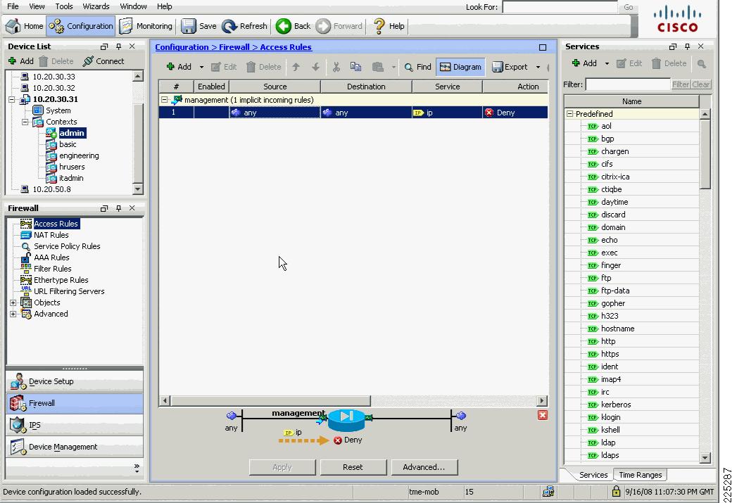
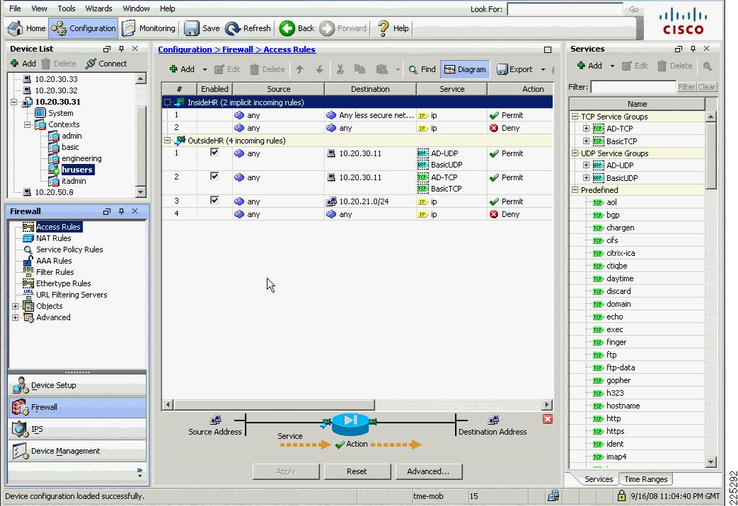
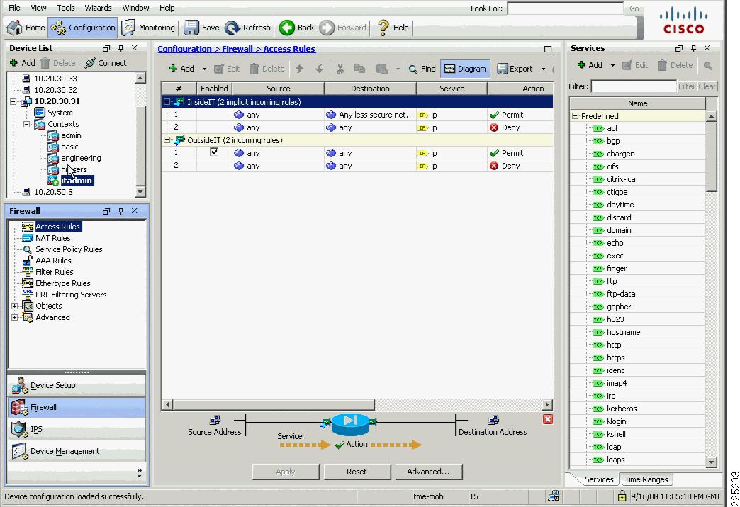
firewall transparenthostname hrusers...!interface GigabitEthernet0/0.153nameif OutsideHRsecurity-level 0!interface GigabitEthernet0/1.53nameif InsideHRsecurity-level 100!...object-group service DM_INLINE_TCP_1 tcpgroup-object AD-TCPgroup-object BasicTCPobject-group service DM_INLINE_UDP_1 udpgroup-object AD-UDPgroup-object BasicUDPaccess-list OutsideHR_access_in extended permit udp any host 10.20.30.11 object-group DM_INLINE_UDP_1access-list OutsideHR_access_in extended permit tcp any host 10.20.30.11 object-group DM_INLINE_TCP_1access-list OutsideHR_access_in extended permit ip any 10.20.21.0 255.255.255.0...access-group OutsideHR_access_in in interface OutsideHRFigure 6-28 IT Admin Security Context Configuration
High Availability
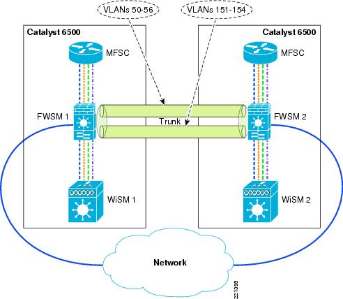
The FWSM configuration presented earlier in this document addresses the configuration of a standalone FWSM/WiSM combination. In many instances, a high availability configuration is required to ensure continuous operation in the event of the FWSM becoming unavailable because of maintenance or failure. A sample high availability schematic is shown in Figure 6-29, where two 6500s are each equipped with WiSMs and FWSMs are connected via a trunk bridging the FWSM VLANs between the two 6500s.
For more information about ASA high availability configuration, refer to to the following URL:
Figure 6-29 FWSM High Availability
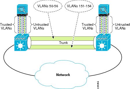
Figure 6-30 ASA High Availability
Spanning Tree and BPDUs
In a network configuration such as shown in Figure 6-29, a loop can be created between the two 6500s as a result of the FWSM or ASA bridging the untrusted/trusted VLANs together.
The failover features of the FWSM or ASA prevent this Layer 2 loop from occurring by ensuring that only one FWSM or ASA security context between the HA pair is forwarding traffic.
In case of FWSM or ASA failover misconfiguration, an additional step to take to prevent these loops is to ensure that spanning tree BPDUs are passed by the firewall. The spanning tree configuration of the 6500 does not protect against loops because the default FWSM or ASA access policy blocks spanning tree BPDUs. Each VLAN configuration within each security context in the FWSM or ASA must be configured with an access list to pass spanning tree BPDUs. These are included in the configuration examples in FWSM or ASA Configuration.
Allowing BPDUs to pass through the FWSM or ASA may create a security exposure in some situations. In this topology, however, the WiSM (in addition to the other WLCs) does not pass spanning tree Ethertypes from WLAN clients, so permitting spanning tree BPDUs through the FWSM or ASA should have no adverse security impact. It is not mandatory for the BPDUs to pass-through because normal FWSM failover operation prevents Layer 2 loops from occurring if implemented correctly.
Note
WLAN Client Roaming and Firewall State
Apart from Layer 2 loop considerations, the FWSM module or ASA must consider the protocol state information that is maintained for all traffic flows through the firewall. In the HA configuration, the FWSM or ASA must ensure that client traffic flows through the same FWSM or ASA and that the failover FWSM is kept up-to-date with the protocol state data. This is achieved through the FWSM or ASA failover configuration.
The FWSM has the following two failover options:
•
•
Active/active is the most appropriate choice in this case because it shares the load across the FWSMs or ASAs without impacting client mobility.
The following configuration example shows the additional failover configuration parameters of the FWSM 1. The configuration for FWSM 2 is identical, except for changing failover LAN unit primary to failover LAN unit secondary. The mode of FWSM must be set to either single or multiple context. Apart from this, the failover system copies the FWSM 1 configuration to FWSM 2 and maintains configuration synchronization.
Note
interface Vlan55description LAN Failover Interface!interface Vlan56descriptionSTATE Failover Interface!.....failoverfailover lan unit primaryfailover lan interface failover Vlan55failover polltime unit msec 500 holdtime 3failover polltime interface 3failover replication httpfailover link STATE Vlan56failover interface ip failover 12.20.200.1 255.255.255.0 standby 12.20.200.2failover interface ip STATE 12.20.201.1 255.255.255.0 standby 12.20.201.2failover group 1preemptfailover group 2secondarypreempt 5admin-context admincontext adminallocate-interface Vlan50config-url disk:/admin.cfgjoin-failover-group 1!context engineeringallocate-interface Vlan152allocate-interface Vlan52allocate-interface Vlan57config-url disk:/engineering.cfgjoin-failover-group 2!context staffallocate-interface Vlan151allocate-interface Vlan153allocate-interface Vlan154allocate-interface Vlan51allocate-interface Vlan53allocate-interface Vlan54allocate-interface Vlan58config-url disk:/staff.cfgjoin-failover-group 1For each FWSM context configured, standby addresses and monitor interfaces need to be configured, as shown in the following examples:
•
interface BVI57ip address 10.20.57.7 255.255.255.0 standby 10.20.57.8...monitor-interface InsideEng•
interface BVI58ip address 10.20.58.7 255.255.255.0 0 standby 10.20.58.8...monitor-interface InsideBasicmonitor-interface InsideHRmonitor-interface InsideAdminLayer 2 and Layer 3 Roaming
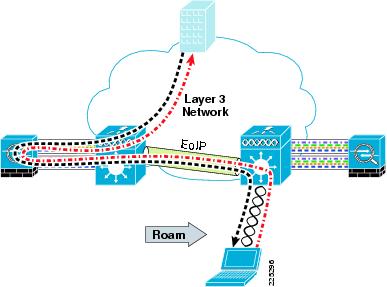
Before the 4.1 code release of WLC firmware, WLAN client roaming across different subnets, although transparent to the WLAN client, resulted in asymmetric client traffic flows. Traffic destined to the WLAN client was sent to the "anchor" WLC of the client where it was tunneled to the foreign WLC via an EoIP tunnel. However, traffic being sent by the WLAN client was forwarded into the network directly by the foreign WLC, as shown in Figure 6-31 and Figure 6-32.
Figure 6-31 Asymmetric Layer 3 Roam
Figure 6-32 ASA Asymmetric Layer 3 Roam
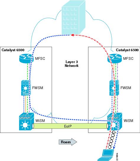
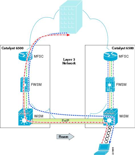
With the 4.1 code release, there is an option (turned off by default) for the Layer 3 roaming to be symmetric, as shown in Figure 6-33. This relaxes the requirement for WLAN clients to be limited to Layer 2 roaming. With Release 5.2, symmetric tunnelling is the default tunneling mode.
Figure 6-33 FWSM Symmetric Layer 3 Roaming
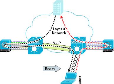
Figure 6-34 ASA Symmetric Layer 3 Roaming
Architectural Impact of Symmetric Layer 3
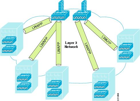
Before the availability of symmetric Layer 3 roaming, firewalled WLANs needed to ensure that a client stayed on the same VLAN to ensure that the WLAN client traffic traversed the same firewall. This limited WLC firewall solutions to centralized deployments, shown in Figure 6-35, unless it could be ensured that WLAN clients would not perform a Layer 3 roam.
Figure 6-35 Centralized Deployment
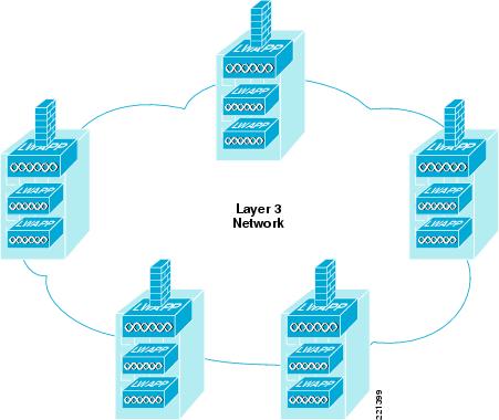
With symmetric Layer 3 roaming, WLC firewall solutions can be distributed, as shown in Figure 6-36, and still support Layer 3 roaming.
Figure 6-36 Distributed Deployment
Configuration Changes for Symmetric Layer 3 Roaming
Of the configuration examples shown in this document, there are no fundamental changes in the configuration if using the distributed WLC model of Figure 6-36, because it is simply the same configuration in multiple locations, with appropriate subnet changes. The config mobility symmetric-tunneling enable command enables symmetric Layer 3 roaming on WLCs.
Note
Layer 3 Roaming is Not Mobile IP
When considering deployments that rely on Layer 3 roaming, it is important to understand that Layer 3 roaming is not the same as Mobile IP. The key point is that Layer 3 roaming allows clients to keep the same IP address when they move to different subnets within the mobility group of a Unified Wireless deployment only.
Mobile IP allows clients to be statically assigned an IP address, and to maintain their connections using that IP address within any network (WLAN, cellular WAN, and so on) that has connectivity to the mobile IP home agent of the client. Layer 3 roaming allows WLAN clients to get their address on a home subnet, and allows clients to maintain that connection if their WLAN roaming takes them to a different subnet. Although the Mobile IP address mapping is a static configuration, the Layer 3 roaming is dynamic and is built on the WLC mobility group having learned the IP address and subnet of a client when it associates with a WLAN.
Combining NAC and a Firewall
As part of the design testing for this chapter consideration was given to the requirement for the ASA firewall and NAC appliance to be used in combination. When using the NAC appliance in virtual gateway mode and the ASA acting as a transparent firewall, this is a relatively simple process of cabling and VLAN assignment. A schematic is shown in Figure 6-37.
VLANs from the WiSM are mapped to the untrusted interface of the NAC appliance and posture assessment performed. The client devices pass their posture assessment and their traffic passes to the ASA untrusted VLAN interface where and appropriate policy is applied. If RADIUS SSO is used by the NAC appliance, no changes need to be made to the ASA firewall policies. But if Active Directory SSO is being used by NAC, the ASA Firewall Policies must allow specific TCP and UDP ports as discussed earlier in the chapter. These ports would most likely already be allowed in a firewall implementation that had been designed to support Microsoft Active Directory Clients.
Figure 6-37 ASA and NAC Appliance in Series
Branch WLC Deployments and IOS Firewall
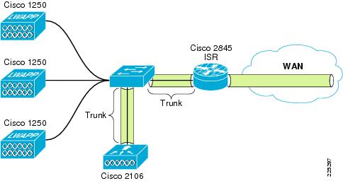
Figure 6-38 shows a schematic of the basic network configuration for testing the branch network. The network consisted of a Cisco 3845 ISR connected back to the campus core through an IPSec VPN. The local network for the branch consisted of a 3750G switch connected to the ISR router through a dot1q trunk. The 3750G connected a 2106 WLC through a trunk connection and also connected 1250 APs to the local network. Other Cisco ISRs, LAN switches, and 2100 family WLCs would be equally applicable in this simple topology.
Figure 6-38 Branch Topology
The basic principles and WLC configuration discussed in the campus deployments are equally applicable in the branch, that is identity-based VLAN assignment as part of the the EAP authentication process. The difference in this branch example is the use of the IOS firewall instead of an FWSM or ASA. Although IOS Firewall is used in this example, an ASA could also be used.
SDM
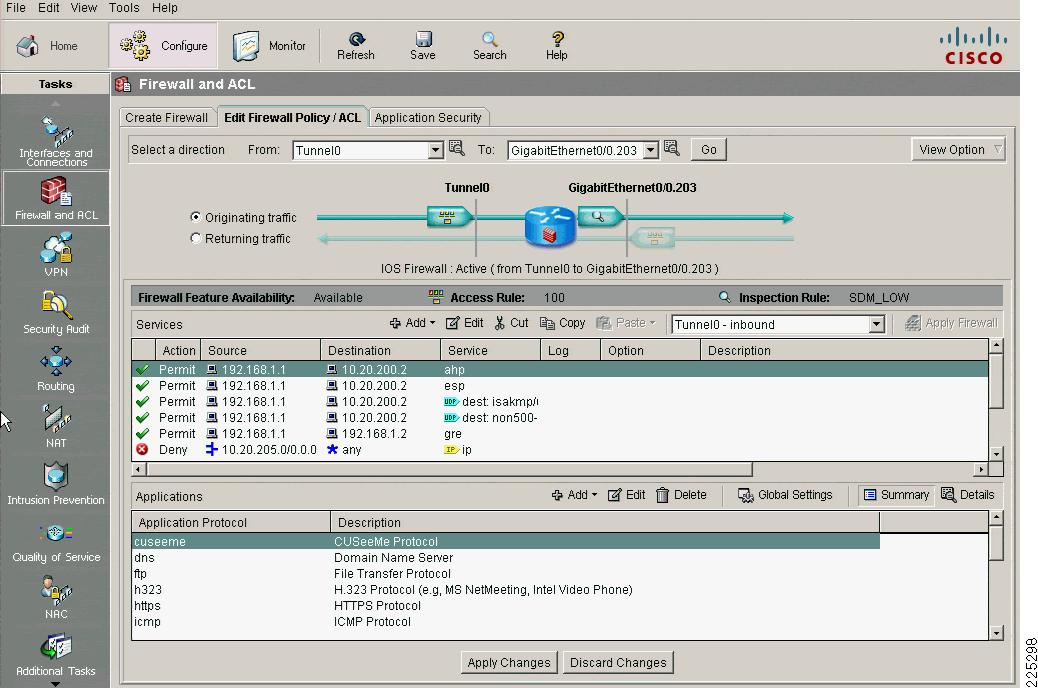
Similar to the ASA and FWSM, a configuration GUI is available to assist in the configuration of of the ISR, including the firewall configuration. The GUI interface for the ISR is called the Security Device Manager (SDM); an example is shown in Figure 39.
Figure 6-39 Firewall and ACL Configuration on the SDM
In this branch example a simplified version of the campus deployment was used, with two different policies being implemented. A basic used with limited HTTPS access to one host and another user with open access.
SDM was used to create these configurations, and the related CLI configuration is shown below.
General IOS Firewall Inspect Statement
ip inspect name SDM_LOW cuseemeip inspect name SDM_LOW dnsip inspect name SDM_LOW ftpip inspect name SDM_LOW h323ip inspect name SDM_LOW httpsip inspect name SDM_LOW icmpip inspect name SDM_LOW netshowip inspect name SDM_LOW rcmdip inspect name SDM_LOW realaudioip inspect name SDM_LOW rtspip inspect name SDM_LOW sqlnetip inspect name SDM_LOW streamworksip inspect name SDM_LOW tftpip inspect name SDM_LOW tcpip inspect name SDM_LOW udpip inspect name SDM_LOW vdoliveip inspect name SDM_LOW httpBasic Policy
access-list 101 remark auto generated by SDM firewall configurationaccess-list 101 remark SDM_ACL Category=1access-list 101 deny ip 10.20.200.0 0.0.0.3 anyaccess-list 101 permit icmp any 10.20.0.0 0.0.255.255 echo-replyaccess-list 101 permit icmp any 10.20.0.0 0.0.255.255 time-exceededaccess-list 101 permit icmp any 10.20.0.0 0.0.255.255 unreachableaccess-list 101 permit udp any eq bootps host 10.20.30.11 eq bootpsaccess-list 101 permit udp any host 10.20.30.11 eq domainaccess-list 101 permit tcp any host 10.20.30.14 eq 443access-list 101 deny ip 10.0.0.0 0.255.255.255 anyaccess-list 101 deny ip 172.16.0.0 0.15.255.255 anyaccess-list 101 deny ip 192.168.0.0 0.0.255.255 anyaccess-list 101 deny ip 127.0.0.0 0.255.255.255 anyaccess-list 101 deny ip host 255.255.255.255 anyaccess-list 101 deny ip host 0.0.0.0 anyaccess-list 101 deny ip any any loginterface GigabitEthernet0/0.203description wlan203 subnet$FW_OUTSIDE$encapsulation dot1Q 203ip address 10.20.203.5 255.255.255.0ip access-group 101 inip verify unicast reverse-pathip helper-address 10.20.30.11ip inspect SDM_LOW outsnmp trap ip verify drop-ratestandby 103 ip 10.20.203.1standby 103 preemptstandby 103 track Serial0/0/0Open Access Policy
access-list 102 remark auto generated by SDM firewall configurationaccess-list 102 remark SDM_ACL Category=1access-list 102 deny ip 10.20.200.0 0.0.0.3 anyaccess-list 102 permit icmp any 10.20.0.0 0.0.255.255 echo-replyaccess-list 102 permit icmp any 10.20.0.0 0.0.255.255 time-exceededaccess-list 102 permit icmp any 10.20.0.0 0.0.255.255 unreachableaccess-list 102 permit udp any eq bootps host 10.20.30.11 eq bootps logaccess-list 102 permit ip 10.20.205.0 0.0.0.255 anyaccess-list 102 deny ip 172.16.0.0 0.15.255.255 anyaccess-list 102 deny ip 192.168.0.0 0.0.255.255 anyaccess-list 102 deny ip 127.0.0.0 0.255.255.255 anyaccess-list 102 deny ip host 255.255.255.255 anyaccess-list 102 deny ip host 0.0.0.0 anyaccess-list 102 deny ip any any loginterface GigabitEthernet0/0.205description wlan205 subnet$FW_OUTSIDE$encapsulation dot1Q 205ip address 10.20.205.5 255.255.255.0ip access-group 102 inip verify unicast reverse-pathip helper-address 10.20.30.11ip inspect SDM_LOW outsnmp trap ip verify drop-ratestandby 105 ip 10.20.205.1standby 105 priority 110standby 105 preemptstandby 105 track Serial0/0/0H-REAP
An H-REAP AP may be used in some branch deployments and the basic configuration principles are the same. The important caveat in the H-REAP case is the H-REAP does not currently support identity-based VLAN assignment. Therefore an H-REAP deployment would required multiple SSIDs to implement different policies or require a common firewall policy for all users.
WLCM
The Wireless LAN Controller Module (WLCM) is an intergrated Wireless LAN Controller for Cisco ISR routers and is an another valid design option for a branch deployment. The WLCM and the 21XX service controllers have similar feature sets, and capacities. Even thought the branch testing for this chapter focussed upon a 2106, the design and configuration would be equally applicable for a WLCM deployment.
High Availability
The 2016 WLC does not provide physically redundant interfaces—these are provided on the 4400 series controllers.
There are two primary WLAN high availability feature for the branch deployment:
•
•
Software Versions in Testing
Cisco Catalyst 6500
12.2(18)SXF8
Cisco WiSM
5.0.148.2
Cisco FWSM
3.1(4)
Cisco ASA
8.0(3)
Cisco ACS
4.2(1)
2106
5.0.148.2